My own board (50mm x 30mm)
-
Getting close to final layout myself ....
-
Hi,
i thougt a long time about placing such a booster on the pcb. Its quite difficult to find a good(!) booster. Lots of the cheaper booster draw a lot of current (quiescent current) - like the one behind your link. I tested only 2 until today.
This one: http://www.exp-tech.de/pololu-3-3v-step-up-spannungsregler-u1v10f3?gclid=CPmll6rH0ccCFRI6Gwod884Lxg
and this one: http://www.exp-tech.de/sparkfun-ncp1402-3-3v-step-up-breakout-prt-10967?gclid=CPCv55_H0ccCFUu6GwodKDUHwACurrent consumption differs approx 30uA between those 2 (red 70uA, green 100uA in sleepmode with sensors etc)...
Did you check current-consumption of your booster?Actually i am changing the board size to 50mmx24mm - its a lot cheaper to order from fusionpcb (seeedstudio)...
Thats a lot.
Greetings[▲QUICK EDIT]
Something like this? Booster soldered vertical....In this way you must select with the solder jumper how to power the board (battery direct or via booster)...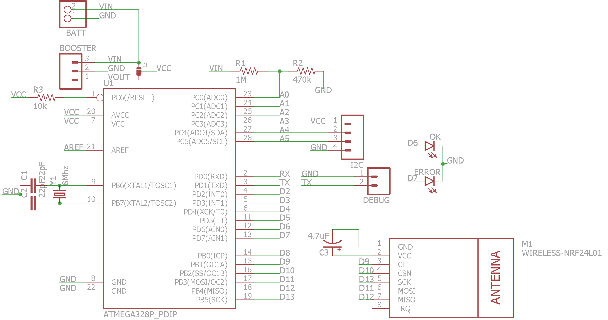
@ahhk said:
Hi,
i thougt a long time about placing such a booster on the pcb. Its quite difficult to find a good(!) booster. Lots of the cheaper booster draw a lot of current (quiescent current) - like the one behind your link. I tested only 2 until today.
This one: http://www.exp-tech.de/pololu-3-3v-step-up-spannungsregler-u1v10f3?gclid=CPmll6rH0ccCFRI6Gwod884Lxg
and this one: http://www.exp-tech.de/sparkfun-ncp1402-3-3v-step-up-breakout-prt-10967?gclid=CPCv55_H0ccCFUu6GwodKDUHwACurrent consumption differs approx 30uA between those 2 (red 70uA, green 100uA in sleepmode with sensors etc)...
Did you check current-consumption of your booster?Actually i am changing the board size to 50mmx24mm - its a lot cheaper to order from fusionpcb (seeedstudio)...
Thats a lot.
Greetings[▲QUICK EDIT]
Something like this? Booster soldered vertical....In this way you must select with the solder jumper how to power the board (battery direct or via booster)... Hi ahhk,
Can You share brd files for this version? Thanks.
Maciej -
Hi,
sure i will share the brd-file and schemativ. No problem. But let me first build one working sensor. I think i will order the pcbs this weekend, because this looks good too =>
-
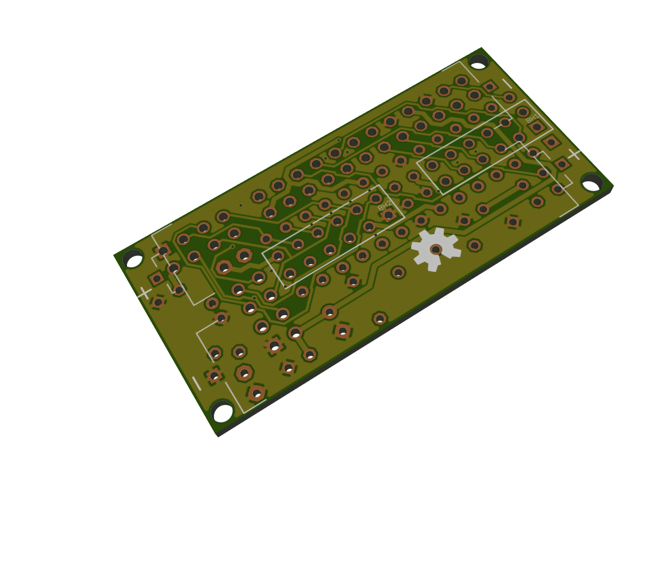
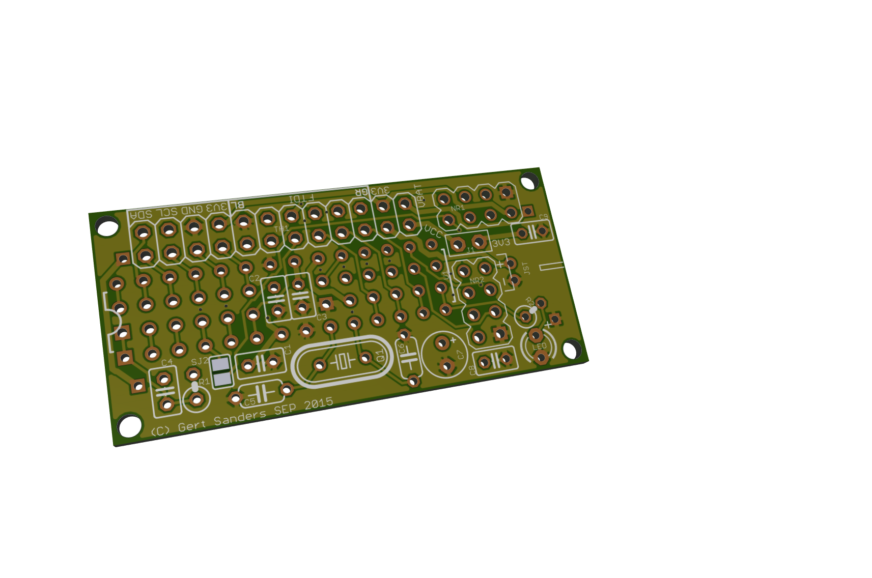
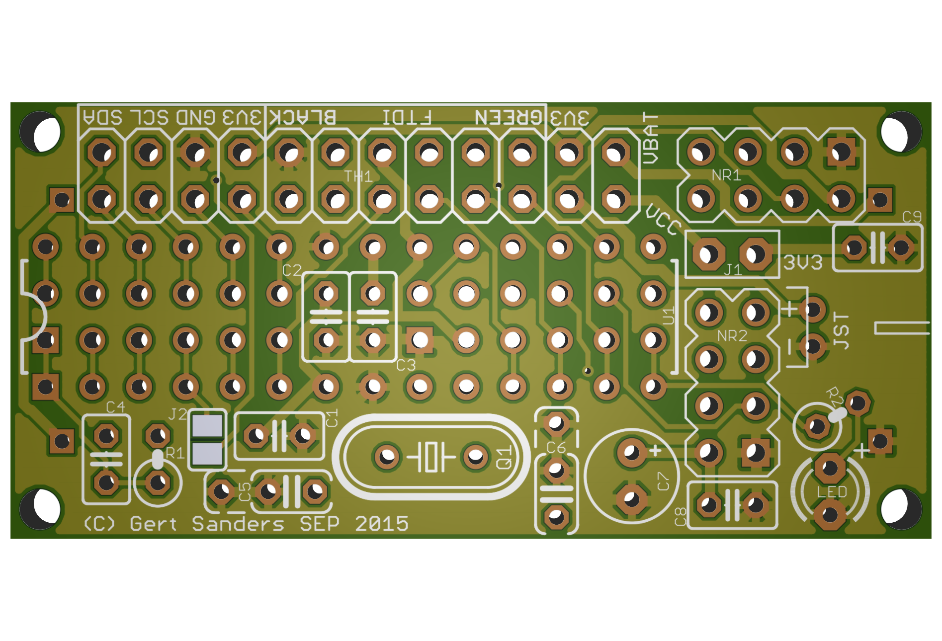
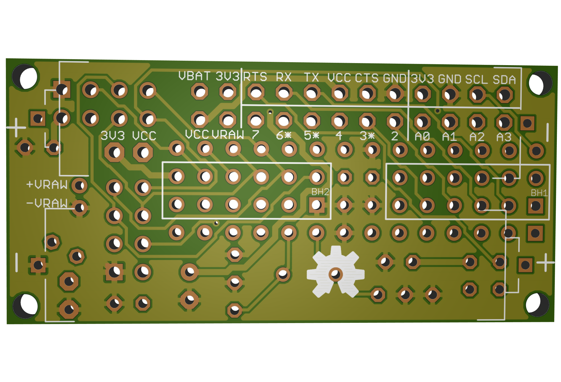
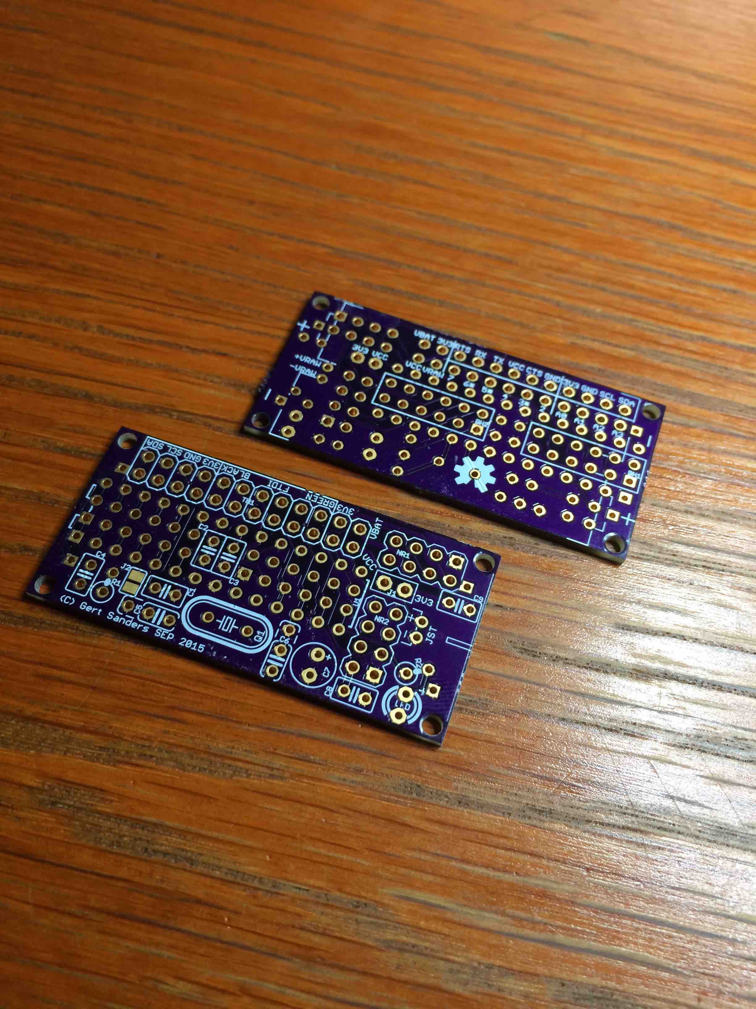
Done, this will be sent to the PCB makers:
Top:
Bottom:
-
each boards are nice, good work :wink:
-
PCBs are ordered (shenzen2u)....i am very curious about it :)
-
Update: PCBs are shipped via express... :dancers:
-
Update: this arrived in my mail today:
I also ordered a set from DirtyPcbs, which were ready lastweek monday, but are still on their way to me.
Assembly starts tomorrow :-) -
ok, great :) Lets how they look ready....
-
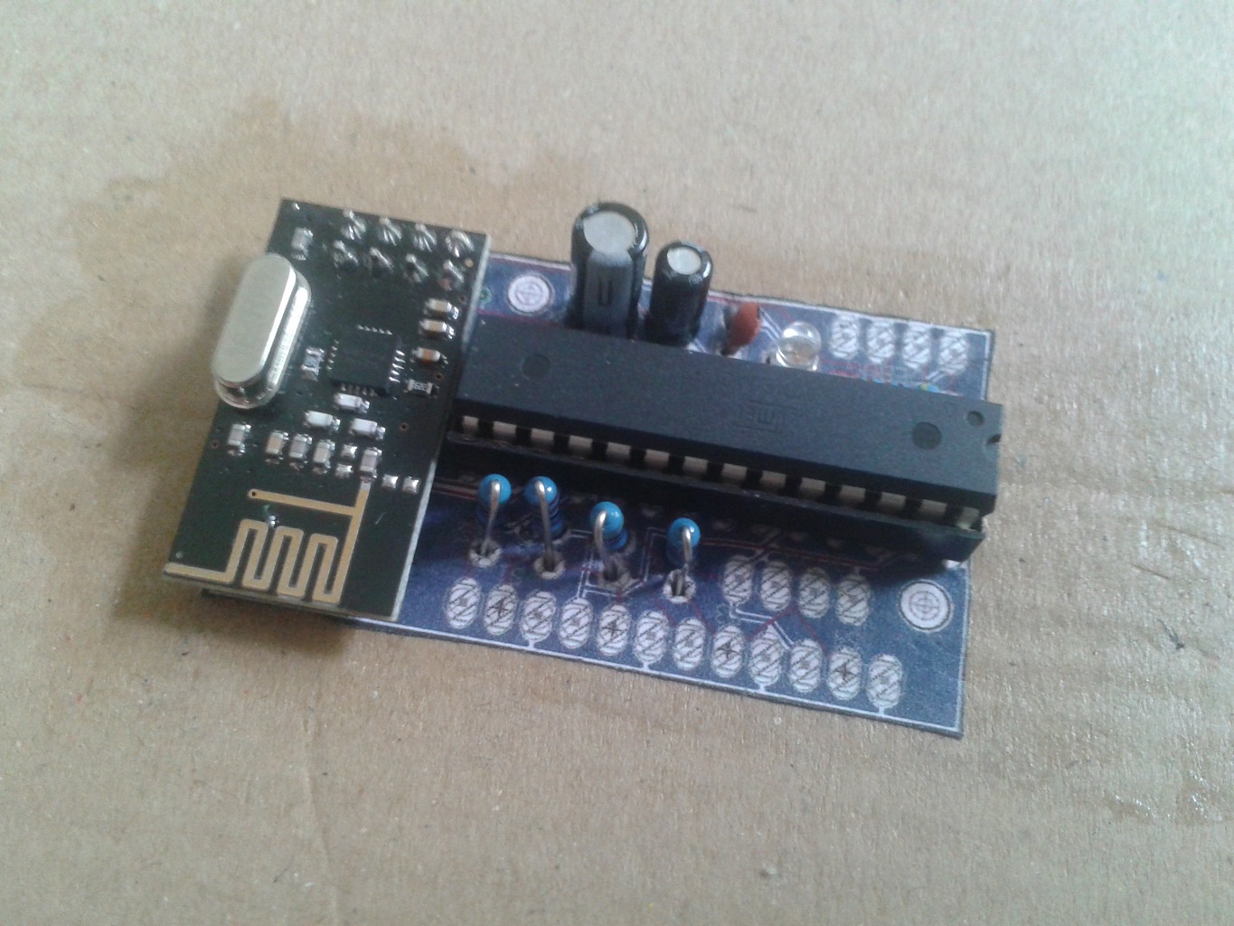
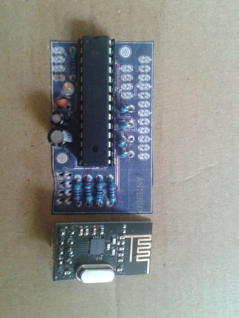
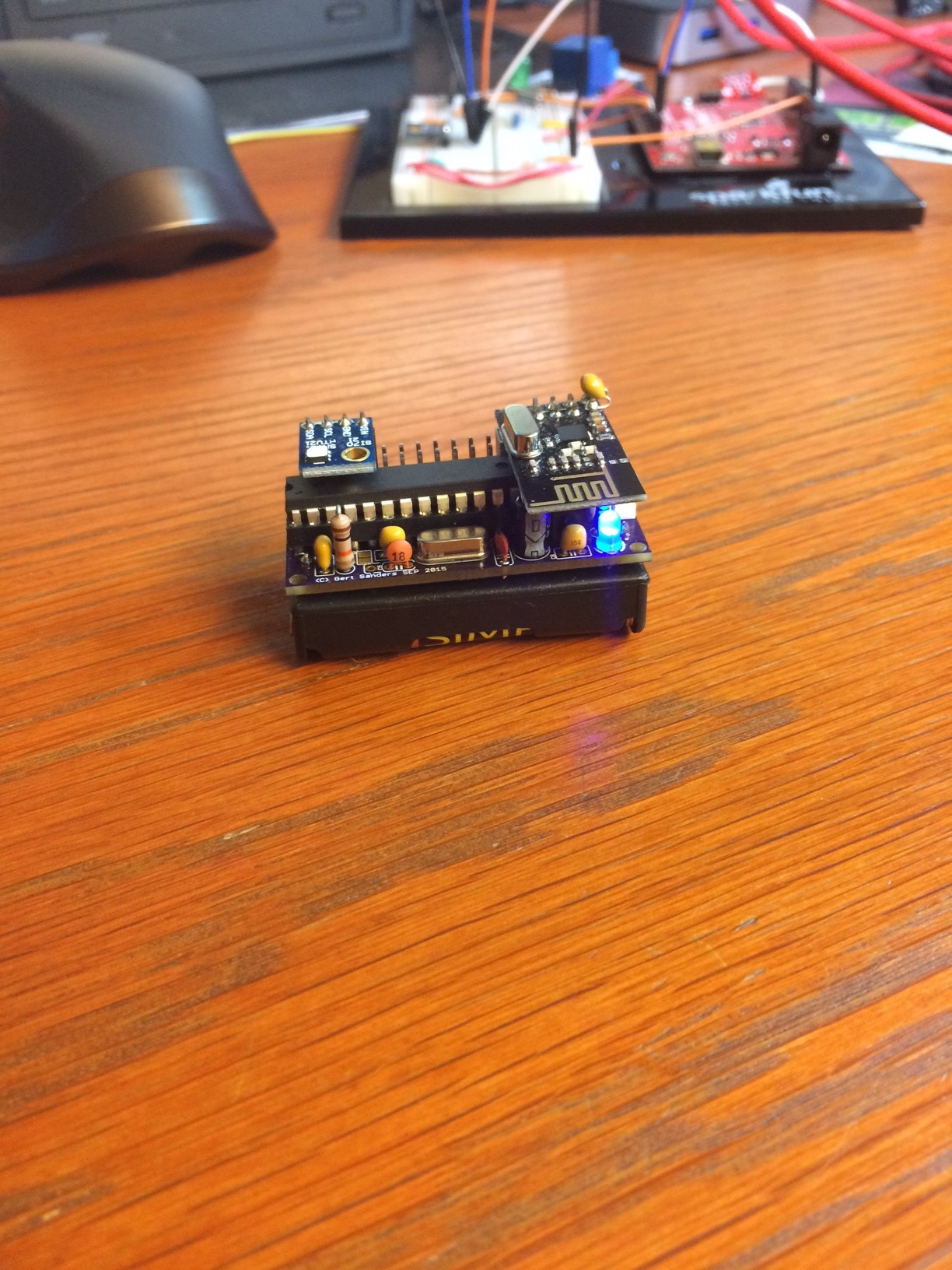
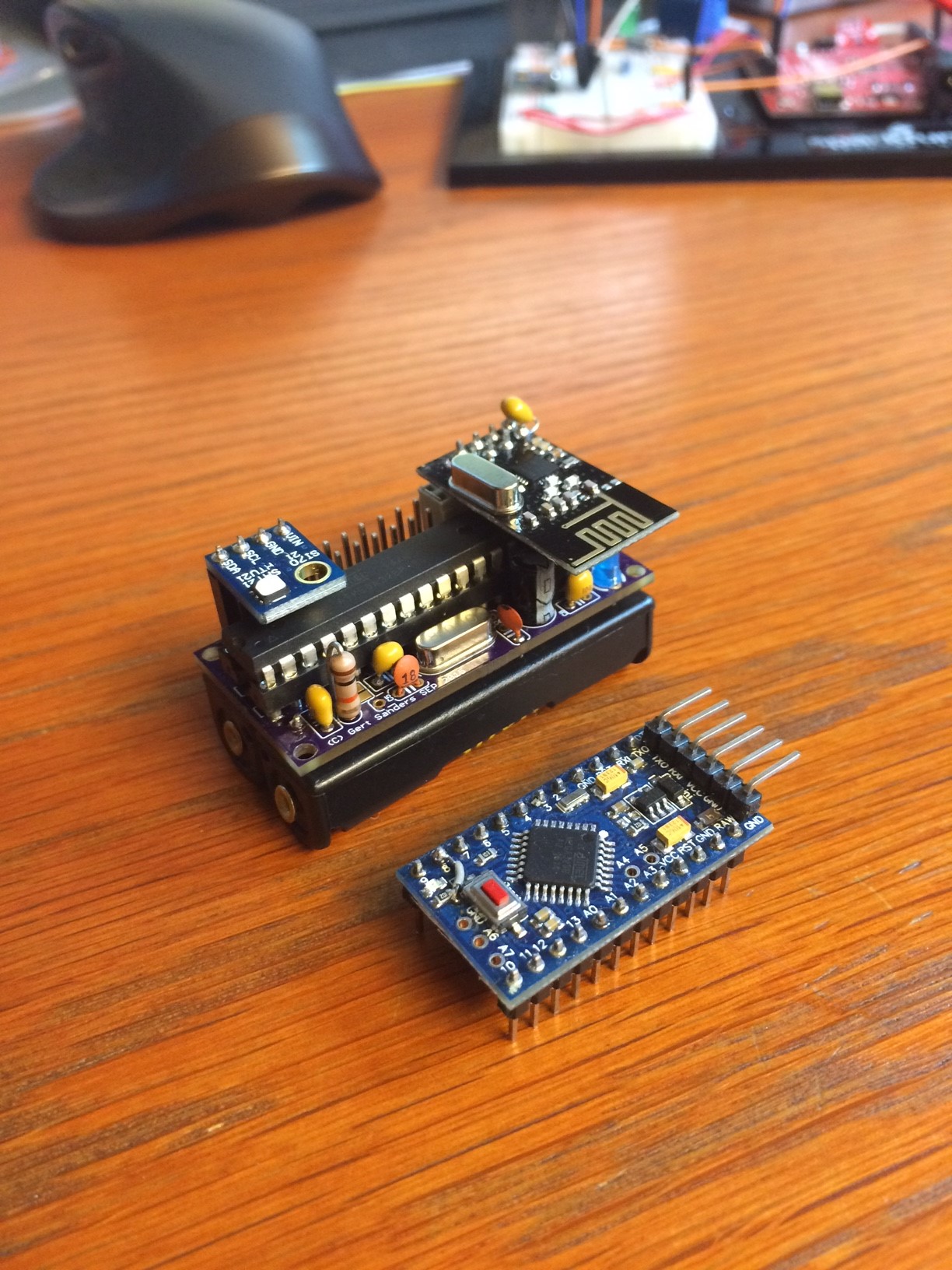
Here is version 2 of my sensor:
-
This post is deleted!
-
Maybe its better to open a new thread for this question? ;)
-
Just realised this. Indeed, I will start a new topic.
-
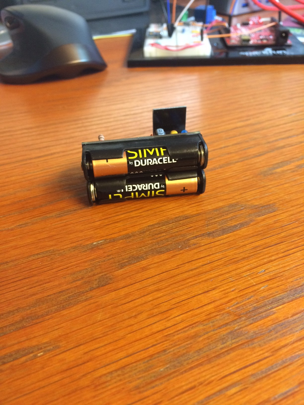
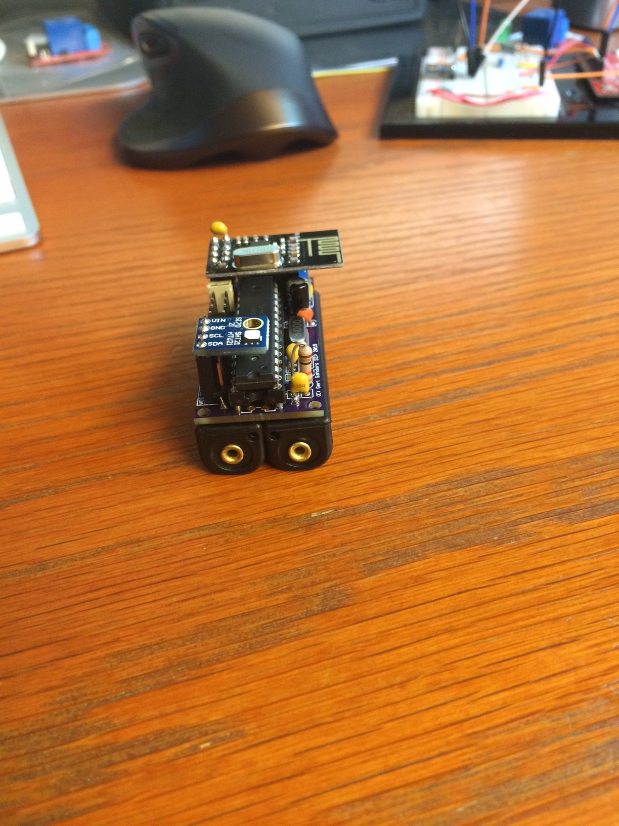
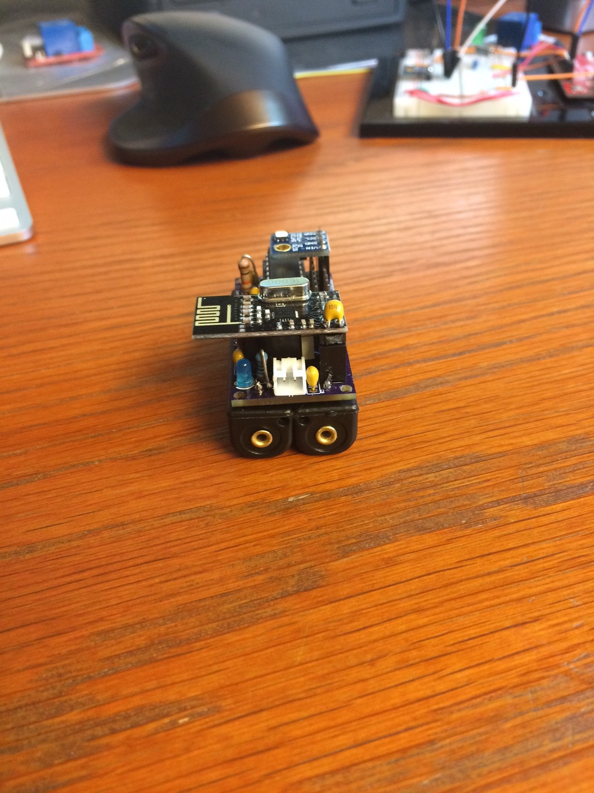
Second variant with the same board. This one actually sends it's messages better (no more st:fail's):
And it's nice and compact. Now I need to find a nice ventilated little box to protect them from dust.
This board is now tested and shared on OSHPark: https://oshpark.com/shared_projects/unP8BmuI
Component values are mentioned in the brd file. I will add a BOM in Excel format later.
-
@GertSanders said:
Now I need to find a nice ventilated little box to protect them from dust.
This might work - it's well ventilated; width & depth OK, but don't know about height.
http://www.ebay.co.uk/itm/291147751395?_trksid=p2060353.m2749.l2649&ssPageName=STRK%3AMEBIDX%3AIT
-
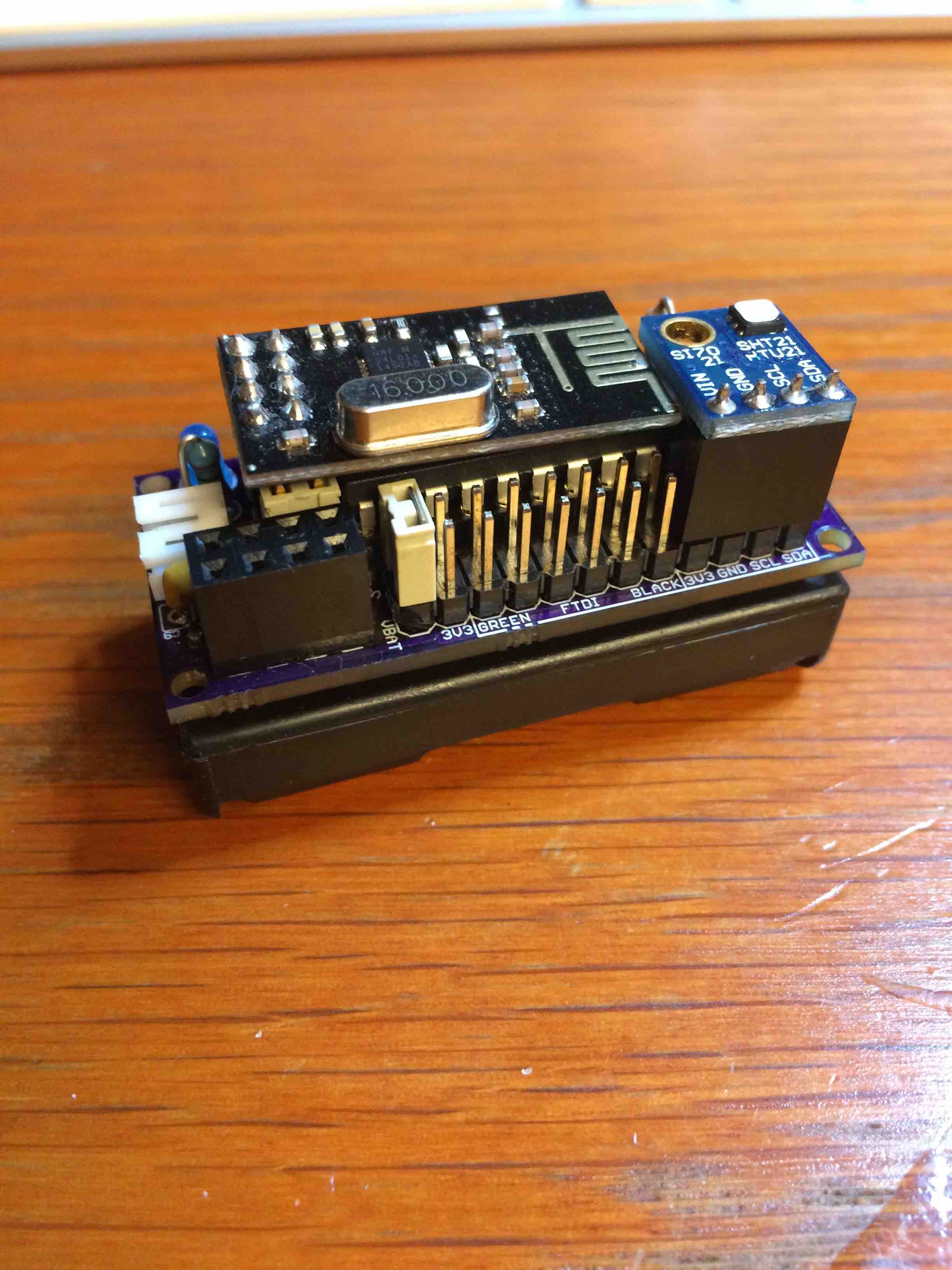
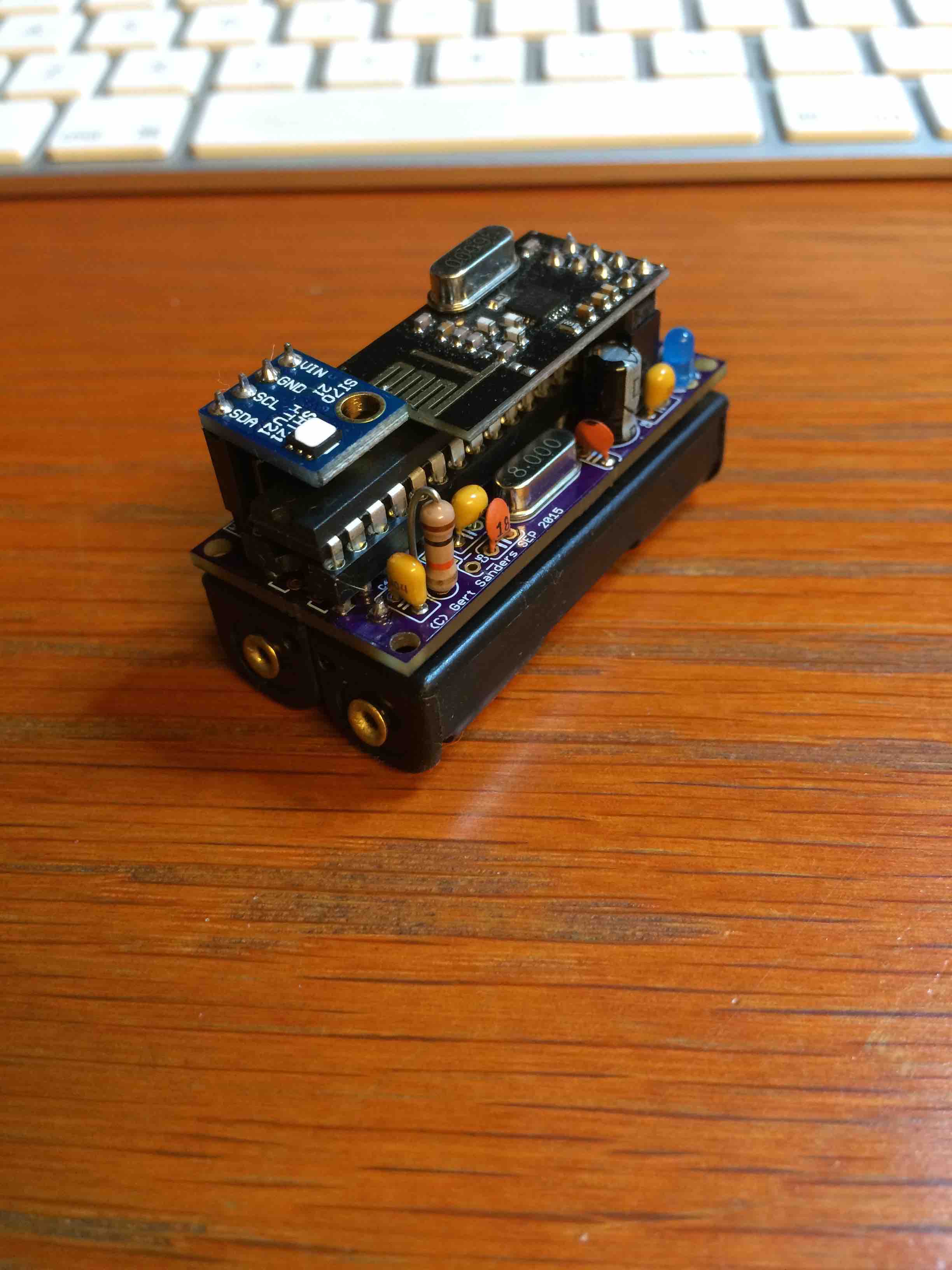
My dirty dirty boards have arrived today :-)
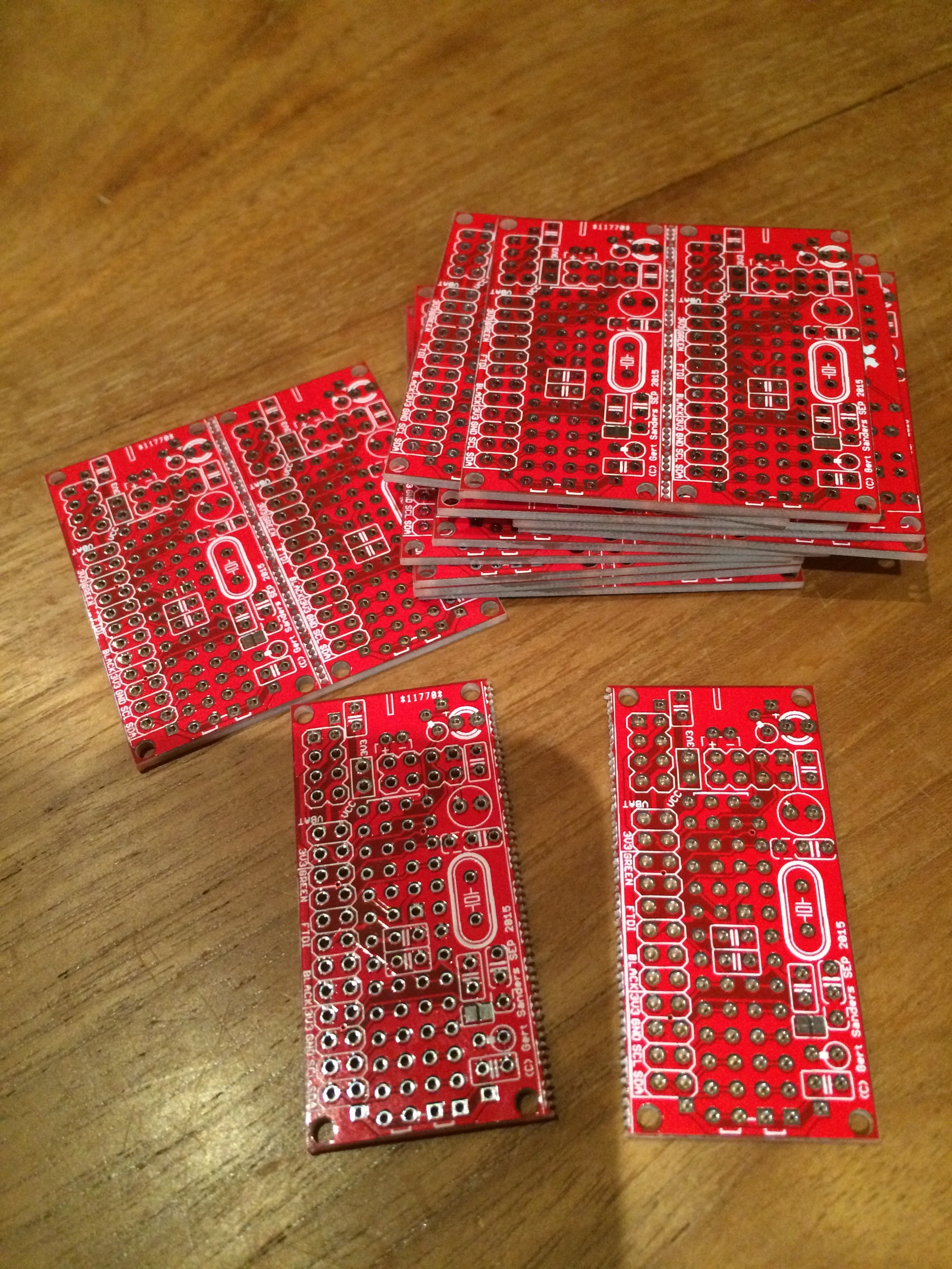
I actually received 12 boards, so I can make 24 sensors, great succes :+1: !!! -
@GertSanders
Please post the BOM. -
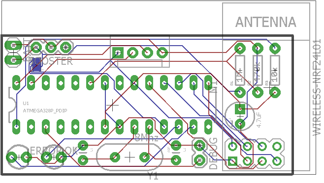
@Didi Here is the BOM and EAGLE files.
selfcontained low power node v1.csv
selfcontained low power node v1.brd
selfcontained low power node v1.sch -
Preview of my latest board, waiting for prototypes to test this ....
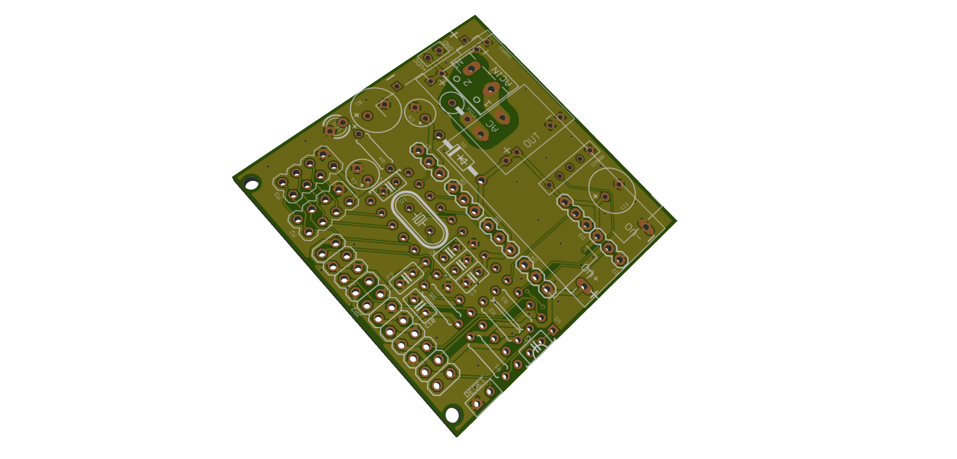
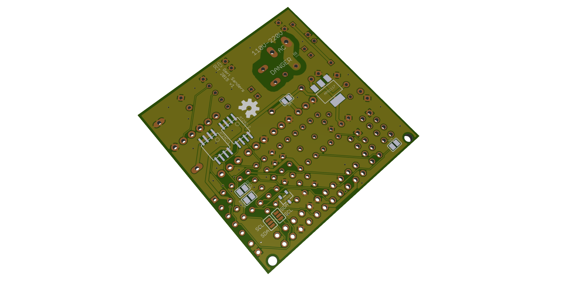
This is a 50x50mm board with multiple powering options (AA or AAA batteries, direct 3.3 or 5V DC, 4.5-20V DC in, 220V AC) and can fit a GSM module at the same time as the NRF24 radio. Allows 2 variants of I2C connection (SDA and SCL on IO header can be swapped via soldering pads). Room for signing chip and some I2C based EEPROM or FRAM memory. Several connectors for digital pins with power.
Fits into this box:
http://www.aliexpress.com/item/Free-shipping-2-pcs-lot-60-58-28mm-plastic-housing-DIY-project-box-ABS-junction-box/2039860908.html
Hello! It looks like you're interested in this conversation, but you don't have an account yet.
Getting fed up of having to scroll through the same posts each visit? When you register for an account, you'll always come back to exactly where you were before, and choose to be notified of new replies (either via email, or push notification). You'll also be able to save bookmarks and upvote posts to show your appreciation to other community members.
With your input, this post could be even better 💗
Register Login