How to wire for battery level measure?
-
I dont understand how to wire if I want to measure battery level at A0 pin.. I have 1MΩ (R1) and 470KΩ (R2) resistor. But how do I connect this?
@msebbe put the two resistors in series between Vcc (Vin) and Gnd and connect the middle ( Vout) to the A0 pin. If you connect the 1 MOhm (R2) to ground, the voltage on the A0 pin is then two third (2/3) times Vcc. This is called a voltage divider.
-
@msebbe put the two resistors in series between Vcc (Vin) and Gnd and connect the middle ( Vout) to the A0 pin. If you connect the 1 MOhm (R2) to ground, the voltage on the A0 pin is then two third (2/3) times Vcc. This is called a voltage divider.
@AWI said:
@msebbe put the two resistors in series between Vcc (Vin) and Gnd and connect the middle ( Vout) to the A0 pin. If you connect the 1 MOhm (R2) to ground, the voltage on the A0 pin is then two third (2/3) times Vcc. This is called a voltage divider.
1M to grund? In example from mysensors picture says 1M to vcc.
Also, could I wire so both resistors meet at A0 or how do you do it?
-
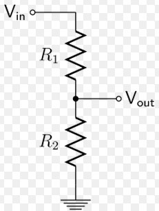
Vin = Vbat
Vout = A0
R1= 1M
R2 = 470k -
@AWI said:
@msebbe put the two resistors in series between Vcc (Vin) and Gnd and connect the middle ( Vout) to the A0 pin. If you connect the 1 MOhm (R2) to ground, the voltage on the A0 pin is then two third (2/3) times Vcc. This is called a voltage divider.
1M to grund? In example from mysensors picture says 1M to vcc.
Also, could I wire so both resistors meet at A0 or how do you do it?
-
@AWI said:
resistors in series between Vcc (Vin) and Gnd and con
Trying to figure out the same thing. Did I understand correctly that I could solder 1M Resistor from VCC to A0 and 470k Resistor from GND to A0 ?
-
@AWI said:
resistors in series between Vcc (Vin) and Gnd and con
Trying to figure out the same thing. Did I understand correctly that I could solder 1M Resistor from VCC to A0 and 470k Resistor from GND to A0 ?
@Cliff-Karlsson You could do just that. The voltage on the A0 pin will be around 1/3th of Vcc. If you swap the resistors 2/3th of Vcc.
Hello! It looks like you're interested in this conversation, but you don't have an account yet.
Getting fed up of having to scroll through the same posts each visit? When you register for an account, you'll always come back to exactly where you were before, and choose to be notified of new replies (either via email, or push notification). You'll also be able to save bookmarks and upvote posts to show your appreciation to other community members.
With your input, this post could be even better 💗
Register Login