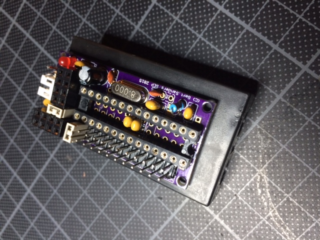
My own board (50mm x 30mm)
-
@GertSanders Hi Gert, on the small board, did you soldered C2 and C3 on the bottom or on top just under/in the IC socket?
-
@pjeterinfo On one of the sensors I soldered it on the bottom between the two connectors on the bottom.
For the sensors where I add the batteryholder on the bottom, I do indeed solder these capacitors on topside between the legs of the chip. Later this evening I will make a photo of such a setup.
-
This is the small board on an AA batteryholder.
-
very good job, i'm very interested to try your board. Did you try to order from
dirtypcbs.com vs oshpark for the price? -
I ordered from both. From OSHPark because they have a 10-12 days turnaroundtime for me (to Belgium) so I could test faster and Dirtypcb because of price (quality is as good, only ENIG is missing). The boards are shared on both manufacturers websites.
More details here:
http://forum.mysensors.org/topic/595/pcb-boards-for-mysensors/30 -
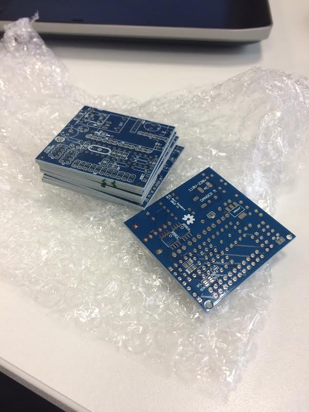
My AC capable boards have arrived in the mail today, some of these will become repeaters, some will be GSM nodes, I know what to do the coming days :-)
-
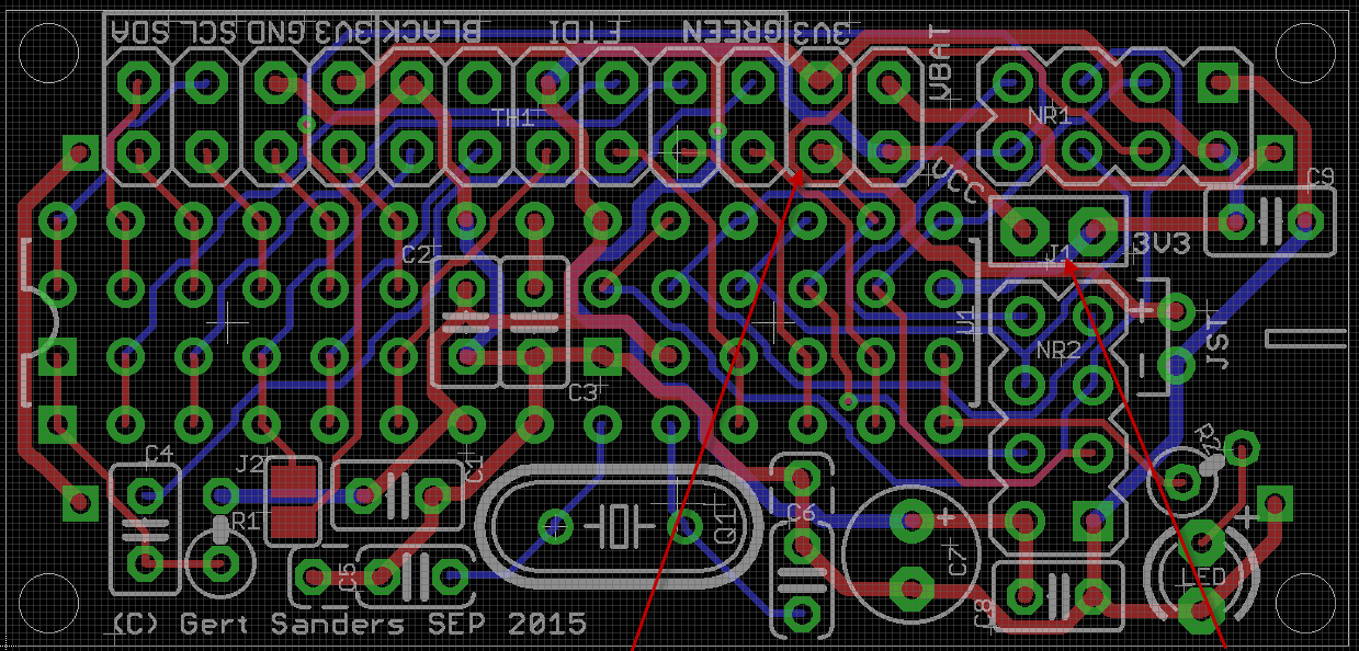
@gloob Here is the diagram: GSRedboard schematic.pdf
This is the same schematic as "selfcontained low power node v1.sch"
Since a Redboard already exists (Sparkfun makes them), I added the GS prefix, but I like the name suggestion :-) -
My dirty dirty boards have arrived today :-)
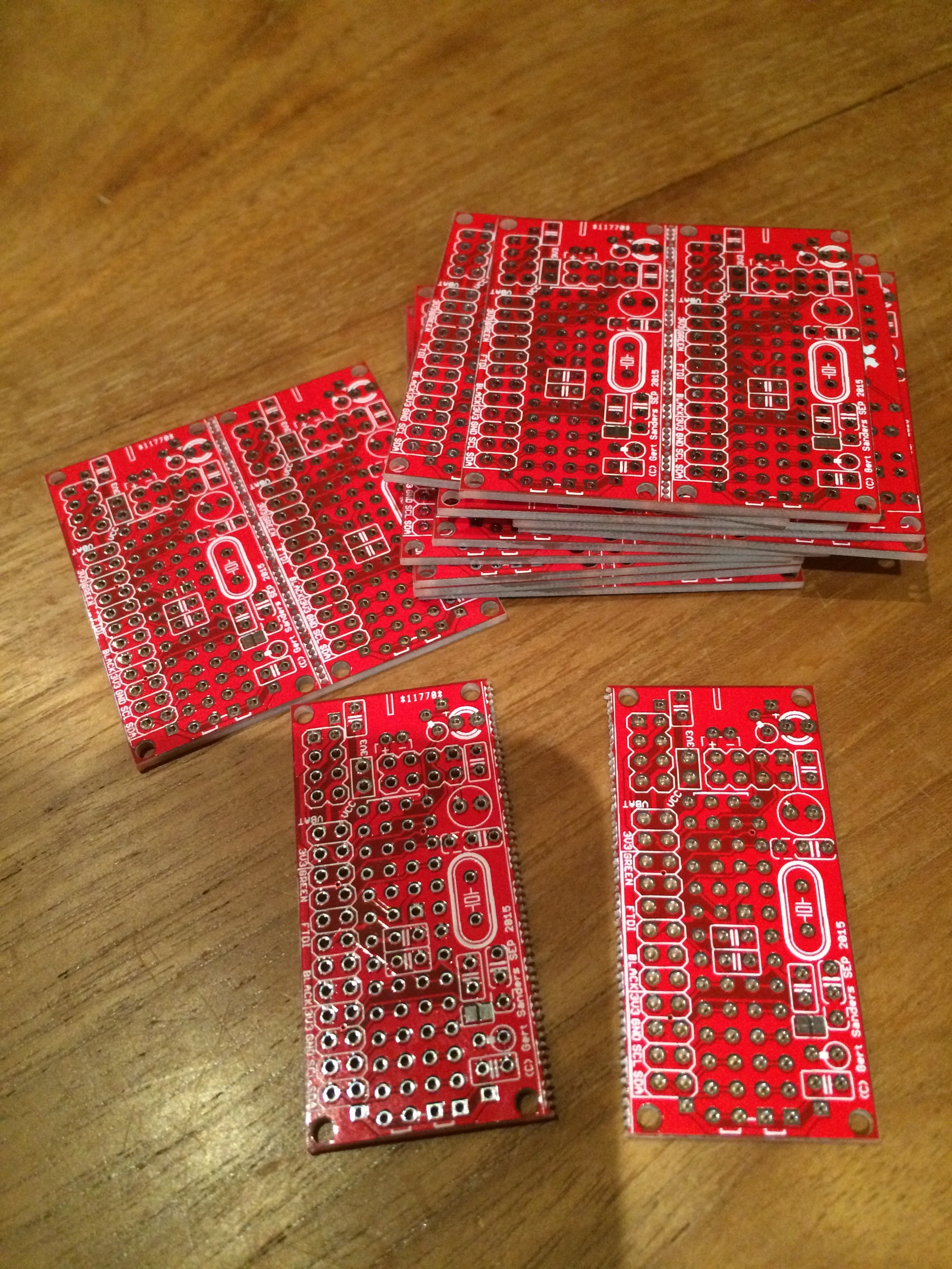
I actually received 12 boards, so I can make 24 sensors, great succes :+1: !!!@GertSanders I don't understand the shipping price on dirtypcb. They say "10 each 5x5cm PCBs $14" so that mean that 10 pcbs boards, each are 5x5 cms will cost 14$, right ?
but when I choose buy, I get confused. In the quantity selection there is protpack +-10 which is 14$, and another option to set the quantity to 10, 20 or 30, it increases the price to 28$Can you please clarify this ? Thanks
-
http://dirtypcbs.com/about.php
If you need a specific quantity of boards the use a more expensive board house. The proto pack will be 10 +/- 1 boards.
-
http://dirtypcbs.com/about.php
If you need a specific quantity of boards the use a more expensive board house. The proto pack will be 10 +/- 1 boards.
@mountainman Thanks. Strange offer to have expect 9 or 12 boards :D
-
@ahmedadelhosni It probably depends on the other boards put on the same panel. A boardhouse makes PCB's in large panels. They fit as much designs as they can on these boards. If you need exactly 10, they will give priority to your design (and it costs more); if not needed, they can add your design to a board and if that means 9 PCB's only, that would be acceptable. For my blue board design I received 11 PCB's, for the red board I received 12, but I would have been OK with 9 or 10 also (given the low price and good quality).
For prototyping I think this is a very good deal. The only minor point: transport time is VERY long, in my case it is 4 weeks between notification that the PCB's are shipped to me and actual delivery to my mailbox. Production is about 1 week. So if you have time (count 5-6 weeks) to get your boards, then DirtyPCB is very good value. If you need prototypes faster (at a little higher expense) I suggest you use OSHPark. You will only get 3 PCB's, but they will be delivered faster (about 3 weeks in my case).
-
@GertSanders
I did now receive the PCBs and ordered the other components via Reichelt.de
I hope to start soldering next week.Do you have any tips to flash the Atmega?
Did you use the normal Arduino IDE?
Do I have to check something special? -
@GertSanders just to let you known i did plat around a little bit with your PCB design and i found a way to use is with-out the crystal by using the ATmega's internal 8 MHz clock
See the results here: http://forum.mysensors.org/topic/2484/running-atmega328p-on-internal-8mhz-clock
The free PCB space (where the clock Cap's and crystal was designed) i now use for the big transmitter capacitor to lay down.
-
@BartE Excellent, of course you can use this without the crystal, depends on your fuse settings :-)
-
@gloob I made my own version of the Optiboot bootloader to flash led on pin 8. I will add the hex file to the site later. To flash the atmega328 I made an extension to the bootloader programmer sketch by Gammon, I will post that as well. It is a translation of my version into his sketch format.
-
Hello,
I have now soldered everything on the board and want to burn the bootloader now.
I have included the bootloader HEX file in the bootloaders folder and modified the boards.txt file.
How do I now burn the bootloader with the Arduino IDE?I have a FDTI programmer but I'm not sure if this is the correct device to burn the bootloader or if I need something different.
-
Is it possible to order the AC boards from your last picture?
-
I order from OSHpark the v2 of your own board and I have a question, if I run it with 2AA battery for example, I put jumpers (marked red on the picture) and it is working.
But if I want to try with 5v input, like from usb charger, do I need to have a 3.3v regulator for the NRF24+ ? And if yes, do I need other pcb to complete this?
Other question, what is the use of the jumper J1? I'm not sure...
Thanks again !!
-
hi @Carl-H By adding the two jumpers as you do, indeed it wil work with a set of batteries.
J1 connects the VCC circuit with the 3V3 circuit.
3V3 circuit connects to the NRF24. Vcc circuit connects to the power (Vcc and AVcc) of the atmega328.
The jumper you put on the left arrow, is to connect the VRaw input with 3V3 (above).
So by adding the two jumpers you get battery voltage on VCC and on 3V3 circuit, through the JST connector (which is connected to VRaw).
If you want to use 5V, you will need to add a 3V3 regulator. This can be through a companion board like I published on OSHPark (https://oshpark.com/shared_projects/IOHUNYT2), or you could make your own board. You could take the VRaw input and bring to down to 3V3 and connect to the 3V3 circuit. If you put a jumper between Vraw pin and VCC pin instead of between VRaw and 3V3, then VCC will have the 5V.
If you use the companion board, you should not bridge the Vcc and 3V3 circuits or the Vcc and 3V3 circuits.As you guessed, to get 3V3 from a 5V input you need more then just this board.
There are also two pins for a battery holder. One is visible above C9, this is the + side and connected to VBat. The other is right of the LED and R2 and is negative side and connected to GND circuit.
More info on this board I will keep adding here: http://forum.mysensors.org/topic/595/pcb-boards-for-mysensors/30
Hello! It looks like you're interested in this conversation, but you don't have an account yet.
Getting fed up of having to scroll through the same posts each visit? When you register for an account, you'll always come back to exactly where you were before, and choose to be notified of new replies (either via email, or push notification). You'll also be able to save bookmarks and upvote posts to show your appreciation to other community members.
With your input, this post could be even better 💗
Register Login