In wall light switch node - Custom PCB
-
@samuel235 I can't tell you what you need, I'm just saying that if you provide an AVR-ISP port looking like FTDI-port, everyone except yourself will be confused or even risk to destroy the AVR by mistake.
Let's look at the Sensbender diagram as a reference. The FTDI-port is JP2 and the AVR-ISP is JP3. Most people would prefer to program bootloader once and then use the FTDI to upload and debug new programs.
If I couldn't fit an AVR ISP port, I would try to make to make the nRF SPI-pin + Reset, accessible. Maybe even better is to make (if you don't already have?) a special board for 328p-AU (TQFP-package) bootloader programming, then solder it in place with bootloader already on it.
Please also note that the JP2 FTDI-port needs R3 and C5 to work.@m26872 Firstly, thank you for referencing the sensebender and its pinout. I can now have a look at this and use it to better improve the pinout and layout of my board. So, i will try to get both headers onto my board to allow better programming capabilities. If i use the same pinout as the sensebender does for the AVR ISP and the FTDI-port, would i then be able to burn the bootloader and upload sketches while the RF module is soldered. If not, do you think i could use some jumper headers to effectively remove the RF module from the board while I upload the sketch and then put the jumpers back on to close the circuit back up?
-
@m26872 Firstly, thank you for referencing the sensebender and its pinout. I can now have a look at this and use it to better improve the pinout and layout of my board. So, i will try to get both headers onto my board to allow better programming capabilities. If i use the same pinout as the sensebender does for the AVR ISP and the FTDI-port, would i then be able to burn the bootloader and upload sketches while the RF module is soldered. If not, do you think i could use some jumper headers to effectively remove the RF module from the board while I upload the sketch and then put the jumpers back on to close the circuit back up?
@samuel235 I can't recall that I've actually used the ISP with the nRF, but the whole point of ISP is that it should work.
-
@samuel235 I can't recall that I've actually used the ISP with the nRF, but the whole point of ISP is that it should work.
@m26872 Okay, so its probably best to just burn the bootloader, then solder the nRF inplace and then upload the sketches using the FTDI port just in case i solder on the nRF then turns out i can't burn the bootloader?
I believe i can leave the AREF pin unconnected. Is this true?
Do you have any other input other than the following changes i'm scheduling to make on the board tomorrow:
- Remove GND plane around the area of nRF module to reduce chance of interference.
- Remove current screw terminals and replace with 1 4-Position with GND as common and other 3 going to input pins.
- Connect all GND pins.
- Connect all VCC pins.
- Add decoupling Caps in the layout that Sensebender uses, 1 on each VCC, so 3 in total.
- Add Pullup to reset pin.
- Remove current 'FTDI' connector and add correct FTDI layout connector along with a SPI header connection for bootloading, use Sensebender for reference of the pinout for these two connectors.
While looking through the Sensebender schematic and images, i have noticed there is Q1 (What i think is a transistor, correct me if i'm incorrect), may i ask if you know what this is for, as it is not actually on the final board images.
Sorry if i have made any more school boy errors.
Sam. -
@m26872 Okay, so its probably best to just burn the bootloader, then solder the nRF inplace and then upload the sketches using the FTDI port just in case i solder on the nRF then turns out i can't burn the bootloader?
I believe i can leave the AREF pin unconnected. Is this true?
Do you have any other input other than the following changes i'm scheduling to make on the board tomorrow:
- Remove GND plane around the area of nRF module to reduce chance of interference.
- Remove current screw terminals and replace with 1 4-Position with GND as common and other 3 going to input pins.
- Connect all GND pins.
- Connect all VCC pins.
- Add decoupling Caps in the layout that Sensebender uses, 1 on each VCC, so 3 in total.
- Add Pullup to reset pin.
- Remove current 'FTDI' connector and add correct FTDI layout connector along with a SPI header connection for bootloading, use Sensebender for reference of the pinout for these two connectors.
While looking through the Sensebender schematic and images, i have noticed there is Q1 (What i think is a transistor, correct me if i'm incorrect), may i ask if you know what this is for, as it is not actually on the final board images.
Sorry if i have made any more school boy errors.
Sam.@samuel235
Arduino Pro Mini should be your no1 reference. Schematics and Eagle files povided. There your can see the normal layout of Q1 e.g. It's the crystal/oscillator (with 22pF caps if you choose xtal) I don't know why Sensebender looks like it does.I haven't studied your design closely or know your intentions, but I don't know of any proven coin cell nRF designs, but I suppose you'll have it sleeping a lot.
Sometimes it's good to breadboard prototypes if there're any hesistance.
-
for coincell, maybe you could add a capacitor near the coincell to absorb spike of power consumption..so the coincell would not discharge too fast with sudden spike ;)
maybe 47u or 100u if you add few sensors in future...100u not very cheap..maybe through hole, there are some not too big. -
@samuel235
Arduino Pro Mini should be your no1 reference. Schematics and Eagle files povided. There your can see the normal layout of Q1 e.g. It's the crystal/oscillator (with 22pF caps if you choose xtal) I don't know why Sensebender looks like it does.I haven't studied your design closely or know your intentions, but I don't know of any proven coin cell nRF designs, but I suppose you'll have it sleeping a lot.
Sometimes it's good to breadboard prototypes if there're any hesistance.
@m26872 I have been looking at a nano i have on my desk while building these designs, and i didn't notice anything with Q1 hense why i asked about it on sensebender. However it is not of any interest to this project (to my knowledge), i just wanted to learn the use of a tran in this case.
I will be sleeping the module quite a bit yeah, literally asleep all the time until someone presses the switch.
@scalz I'll throw a 47u in there, this node shouldn't be used for any other sensor at any time to be honest, hence why i'm designing it from scratch to go into the socket.
-
Tonight i have finished updating my schematic to reflect some of your helpful inputs. Please, again, throw any comments you have regarding my layouts my way so i can further improve the board if needed. Upgrades i have done are:
- Added Capacitors for the VCC lines.
- Added proper pinout/layout for the FTDI header.
- Added a Capacitor on the battery to stop any spikes of current draw.
- Changed the double position screw terminals for a 4 position one.
- Added a pull-up resistor and capacitor on reset pin for the FTDI uploads to be able to reset upon new sketch upload.
Currently i still do not have a SPI header included. Would i be able to survive without one, could i do the sketch upload through the FTDI header at all?
Once i finalize the overall board layout i will know what size i'm working with and IF i can fit a SPI header in, i will install one onto the board. However, because of the limiting space i may struggle on this.
-
Looks proper. I think those two 47uF caps don't necessarily have to be two and can be placed anywhere between vcc and gnd, provided short low resistance traces etc.
-
Looks proper. I think those two 47uF caps don't necessarily have to be two and can be placed anywhere between vcc and gnd, provided short low resistance traces etc.
-
Either you breadboard your design first or make it a flexible pcb design.
Add footprint and make room for bigger or more caps just in case they'll be needed. The physical place shouldn't matter.
Edit: Since someone will object to that last sentence if I don't clarify it .... Physical place of that 47uF near nRF could matter, but if so - it should be fixed with some small low ESR cap near it instead.
@m26872 So just to clarify, do i understand correctly that you're suggesting to remove the battery capacitor, keep the nRF cap in there and just allow a few VCC -> Capacitor -> GND dotted around the board to allow me to add more caps if needed?
-
Ok. Leave the 47u near nRF as it is. Make the footprint for the other 47u one, but make it fit even a 100uF if there's room for it. Only populate if needed. And yes open footprints for 0.1uF caps dotted around is not bad either.
-
Awesome! I have that all sketched out now. For the passive components i have gone with a size of 0603 SMD. Would this be the cheapest? Or would 0805 be for its popularity? Cost of pense isn't really an issue for me however i would like to have a really cheap source price for this board as another positive point for it, but again its not vital.
-
@samuel235: cool.
- I think you need to learn some basic electronics basics guide, it could help you in future to understand because if you want to draw schem, it would be useful, positive feedback ;)
I started to learn elec and uc stuff some years ago(10+), so when I say I am not electronician, it is a small lie :) I am not graduated in this field ;) but my dad, elec engineer, teached me a lot. I am lucky. Now you can have lot infos at sparkfun, adafruit, arduino ....and you are choosing the fun/interesting way, learning learning and learning. - like @m26872 said, it is better, and I like it too when I can, to have footprints.
- for the batt cap, I told you this because of the cr2032 comment..it can prevent the coin cell to discharge too fast. coin cell don't like spikes, this is one of the reason for people choosing alkaline. but you can do lot of stuff with coin cell too. the cap is optional of course.
- If you can have avrspi, better, but if no space. like you said upload bootloader, and then...if you have to reupload it later, just unsolder nrf, not big thing.
- for 0805 or 0603, this is not a question about component cost here...it is much more a question of your soldering skills and available space of course.
I have no problem with 0603, I handsolder some vqfn sensors (very hard stuff...), but what I would advice for noob, a step by step curve. Try 0805 first, then move harder stuff. You will see that you must be careful when soldering atmel tqfp. If all ok, then...pcb are cheap now ;) I hope you have good iron solder, thin wire....
- I think you need to learn some basic electronics basics guide, it could help you in future to understand because if you want to draw schem, it would be useful, positive feedback ;)
-
... and flux.
-
@samuel235: cool.
- I think you need to learn some basic electronics basics guide, it could help you in future to understand because if you want to draw schem, it would be useful, positive feedback ;)
I started to learn elec and uc stuff some years ago(10+), so when I say I am not electronician, it is a small lie :) I am not graduated in this field ;) but my dad, elec engineer, teached me a lot. I am lucky. Now you can have lot infos at sparkfun, adafruit, arduino ....and you are choosing the fun/interesting way, learning learning and learning. - like @m26872 said, it is better, and I like it too when I can, to have footprints.
- for the batt cap, I told you this because of the cr2032 comment..it can prevent the coin cell to discharge too fast. coin cell don't like spikes, this is one of the reason for people choosing alkaline. but you can do lot of stuff with coin cell too. the cap is optional of course.
- If you can have avrspi, better, but if no space. like you said upload bootloader, and then...if you have to reupload it later, just unsolder nrf, not big thing.
- for 0805 or 0603, this is not a question about component cost here...it is much more a question of your soldering skills and available space of course.
I have no problem with 0603, I handsolder some vqfn sensors (very hard stuff...), but what I would advice for noob, a step by step curve. Try 0805 first, then move harder stuff. You will see that you must be careful when soldering atmel tqfp. If all ok, then...pcb are cheap now ;) I hope you have good iron solder, thin wire....
@scalz - This is partially why i'm choosing to do all of this myself, I'm learning electronics while i go. Honestly, its why i have created this topic/thread so i can learn and other can tune in to learn a thing or two as well. I have that Cap wired into the battery if i need it, i will more than likely just put it in anyway to be on the safe side. I think I'm going straight into 0603 SMD tbh, I have a pretty steady hand and have some decent soldering experience. I may need to get myself a expensive/quality soldering iron, i have a cheap(ish) temperature regulated one at the moment. I'm getting some thin solder on order with the parts when i finally order it all.
- I think you need to learn some basic electronics basics guide, it could help you in future to understand because if you want to draw schem, it would be useful, positive feedback ;)
-
cool. so, for soldering, from my own experience, but I will start to use reflow oven, what I can advise you is:
- find a 0.2mm tip for your iron solder. I have a great old weller. but I know someone who have bought a ts100 recently and he is very happy with it! you have large choice to power it, and we can imagine to use lipo with it for ponctual mobile soldering, far better than butane gaz iron solder!. crazy price, quality I don't know but I am very tempted to buy one...
http://www.banggood.com/fr/TS100-Digital-OLED-Programable-Interface-DC-5525-Soldering-Iron-Station-Built-in-STM32-Chip-p-984214.html - a magnifier is a minimum I think. a cheap one is a good start. maybe a 3rd hand..
- thin solder. I use 0.3 but 0.5mm can work I think. Choose good quality for thin solder. some aliexpress thin solder are very bad.
- flux of course. very helpful. I prefer gel or liquid. I don't like aliexpress pen.
- desolder wick. very helpful too.
- tweezers like this for instance:
http://fr.aliexpress.com/item/6pcs-Set-VETUS-Tweezers-Anti-static-ESD-10-15-Tweezers-Set-for-Soldering-Welding-Station/32265054449.html?spm=2114.06010108.3.112.yI04vt&ws_ab_test=searchweb201556_7_79_78_77_82_80_62,searchweb201644_0,searchweb201560_4 - I use isopropil alcool (rubbing alcool I think) to clean my board after soldering..
- solder paste, optional, but helpful sometimes and funny to try
- lots of soldering howto on youtube
- find a 0.2mm tip for your iron solder. I have a great old weller. but I know someone who have bought a ts100 recently and he is very happy with it! you have large choice to power it, and we can imagine to use lipo with it for ponctual mobile soldering, far better than butane gaz iron solder!. crazy price, quality I don't know but I am very tempted to buy one...
-
cool. so, for soldering, from my own experience, but I will start to use reflow oven, what I can advise you is:
- find a 0.2mm tip for your iron solder. I have a great old weller. but I know someone who have bought a ts100 recently and he is very happy with it! you have large choice to power it, and we can imagine to use lipo with it for ponctual mobile soldering, far better than butane gaz iron solder!. crazy price, quality I don't know but I am very tempted to buy one...
http://www.banggood.com/fr/TS100-Digital-OLED-Programable-Interface-DC-5525-Soldering-Iron-Station-Built-in-STM32-Chip-p-984214.html - a magnifier is a minimum I think. a cheap one is a good start. maybe a 3rd hand..
- thin solder. I use 0.3 but 0.5mm can work I think. Choose good quality for thin solder. some aliexpress thin solder are very bad.
- flux of course. very helpful. I prefer gel or liquid. I don't like aliexpress pen.
- desolder wick. very helpful too.
- tweezers like this for instance:
http://fr.aliexpress.com/item/6pcs-Set-VETUS-Tweezers-Anti-static-ESD-10-15-Tweezers-Set-for-Soldering-Welding-Station/32265054449.html?spm=2114.06010108.3.112.yI04vt&ws_ab_test=searchweb201556_7_79_78_77_82_80_62,searchweb201644_0,searchweb201560_4 - I use isopropil alcool (rubbing alcool I think) to clean my board after soldering..
- solder paste, optional, but helpful sometimes and funny to try
- lots of soldering howto on youtube
@scalz Pretty cool list of things there! I'm going to use the soldering iron i have at the moment and see how that stands up to the task. I will be ordering a magnifier, some thin solder, a few tweezers, desolder wick and some alcohol too. I have been doing some pretty basic soldering jobs where i didn't need to pay close attention as much as this in terms of little things like cleaning up the board etc etc. I have soldered and replaced laptop motherboard power connectors and such, completed the PCB Board kits for little projects but nothing as serious as this before. So now is the time my soldering skills are going to be put to the test, and i honestly can't wait! I'm working on my board layout as we speak and i will get this uploaded soon as i am done for a update to the project.
- find a 0.2mm tip for your iron solder. I have a great old weller. but I know someone who have bought a ts100 recently and he is very happy with it! you have large choice to power it, and we can imagine to use lipo with it for ponctual mobile soldering, far better than butane gaz iron solder!. crazy price, quality I don't know but I am very tempted to buy one...
-
I'm very tempted to have some jumper headers or even a dip switch on the board to allow for sketch uploads with the nRF intact. I'm hoping to get some sizings done tomorrow and if i have the room i may have the RF module on a header/socket so i can remove it while uploading a swetch. If not i will have to go with the idea of jumpers or try to rearrange the board to allow a SPI header. I shall see what i can do, upload to this build log and see what you guys think. Again, with shared input we could possibly create a much better suited board then.
Whats your opinions to the jumper pins across the SPI connection on the nRF module to effectivly disconnect the RF while we upload the sketch upgrades?
-
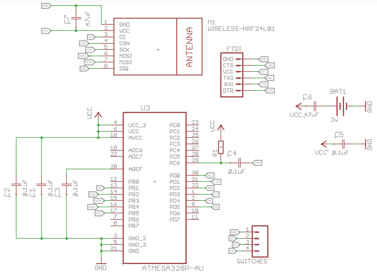
C6 should be in parallel to the battery. In the schematic you show, the C6 would disconnect the battery from Vcc (from DC point of view). If you have Vcc - C6 - battery- GND, then no DC current will flow from Vcc to GND. Is should be:
Vcc -+- battery -+- GND
Vcc -+- C6 -+- GND
Hello! It looks like you're interested in this conversation, but you don't have an account yet.
Getting fed up of having to scroll through the same posts each visit? When you register for an account, you'll always come back to exactly where you were before, and choose to be notified of new replies (either via email, or push notification). You'll also be able to save bookmarks and upvote posts to show your appreciation to other community members.
With your input, this post could be even better 💗
Register Login