Chinese Solar Lipo powered PIR led lamp.
-
Got myself a similar PIR LED lamp. The functionality seems like it is the same but the circuit board is different.
@korttoma
Nice to see some interest in smart solar lamps :)
It looks like an updated version (at least i like it more from your pictures). Could you post an order link.
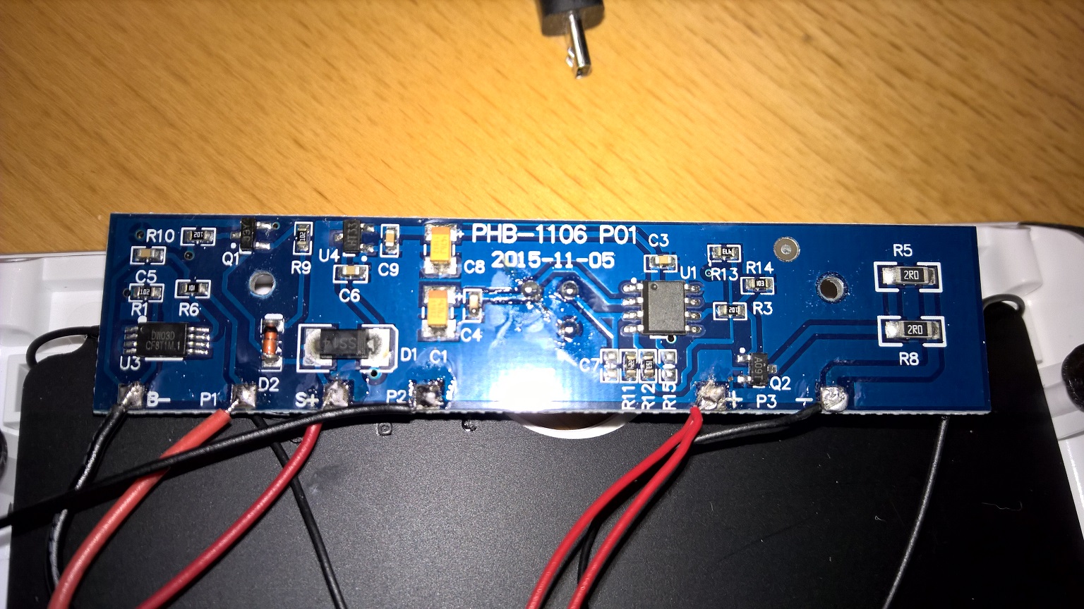
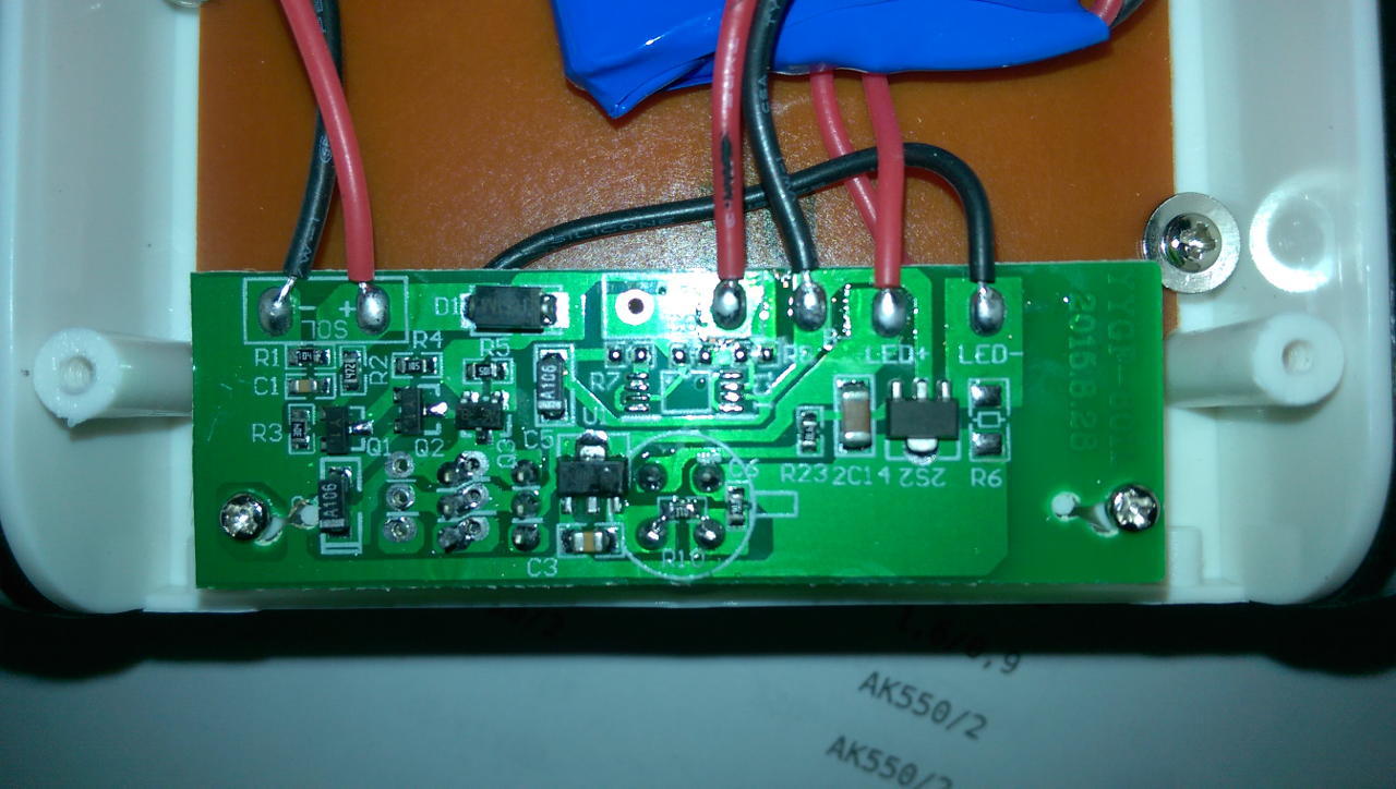
I think this one should be even easier to intercept with "mysensors", beacause i see only two transistors and circuit connectios are clearly visible.so lets try to understand the circuit:
-U3 is probably battery protection circuit- Q1 i think is voltage regulator HT33 - to power arduino wih 3.3V (meassure voltage)
- take a photo of PIR sensor from front side (is there any ic elements)?
- U1 - i would guess PIR sensor IC logic - leg 6 (count from dot on IC) should be output (meassure voltage - high 3,3 V when motion detected):
-if it is output from PIR just remove R3 and IC ouput goes over resistor to you arduino input. - the output goes over resistor to Q2
-whats is left - you have to figure out what drives resistor Q1(J3y) : - i gues its driven by solar cell, than collector is connected to resistor R10, resesitor is than connected over board to the other side.......
-
I guess you meant U4 is the 3.3V regulator. I measured it to 3.3V and HT33 should be a regulator. Q1 and Q2 I think are transistors. U3 handles the solar charging. U1 is for the PIR but unfortunately there is no text on the chip. I will get you the link tomorrow but it is quite easy to find on aliexpress.
- Tomas
-
I guess you meant U4 is the 3.3V regulator. I measured it to 3.3V and HT33 should be a regulator. Q1 and Q2 I think are transistors. U3 handles the solar charging. U1 is for the PIR but unfortunately there is no text on the chip. I will get you the link tomorrow but it is quite easy to find on aliexpress.
@korttoma
sorry my typo: you are correct- U4 - HT33 is voltage regulator
- yes Q1 and Q2 are transistors
- U1 - PIR out test - measure voltage between PIN 6 and R3 when PIR is OF and ON. I think this drives Q2 (high brightness / low brightnes)
also take picture of other side of circuit board, beause i think Q1 is conected to R10 and
then further on the other side -
Here is the link to the one I got but it seems like the prize is allot higher now since I paid 23,84$ including shipping -> http://www.aliexpress.com/item/1-Set-1200-Lumens-46-pcs-LED-Solar-Power-Motion-Sensor-Lamp-Ultra-thin-PIR-Outdoor/32354254209.html
Also it took like 10 weeks for it to arrive so maybe another seller would be a better fit.
-
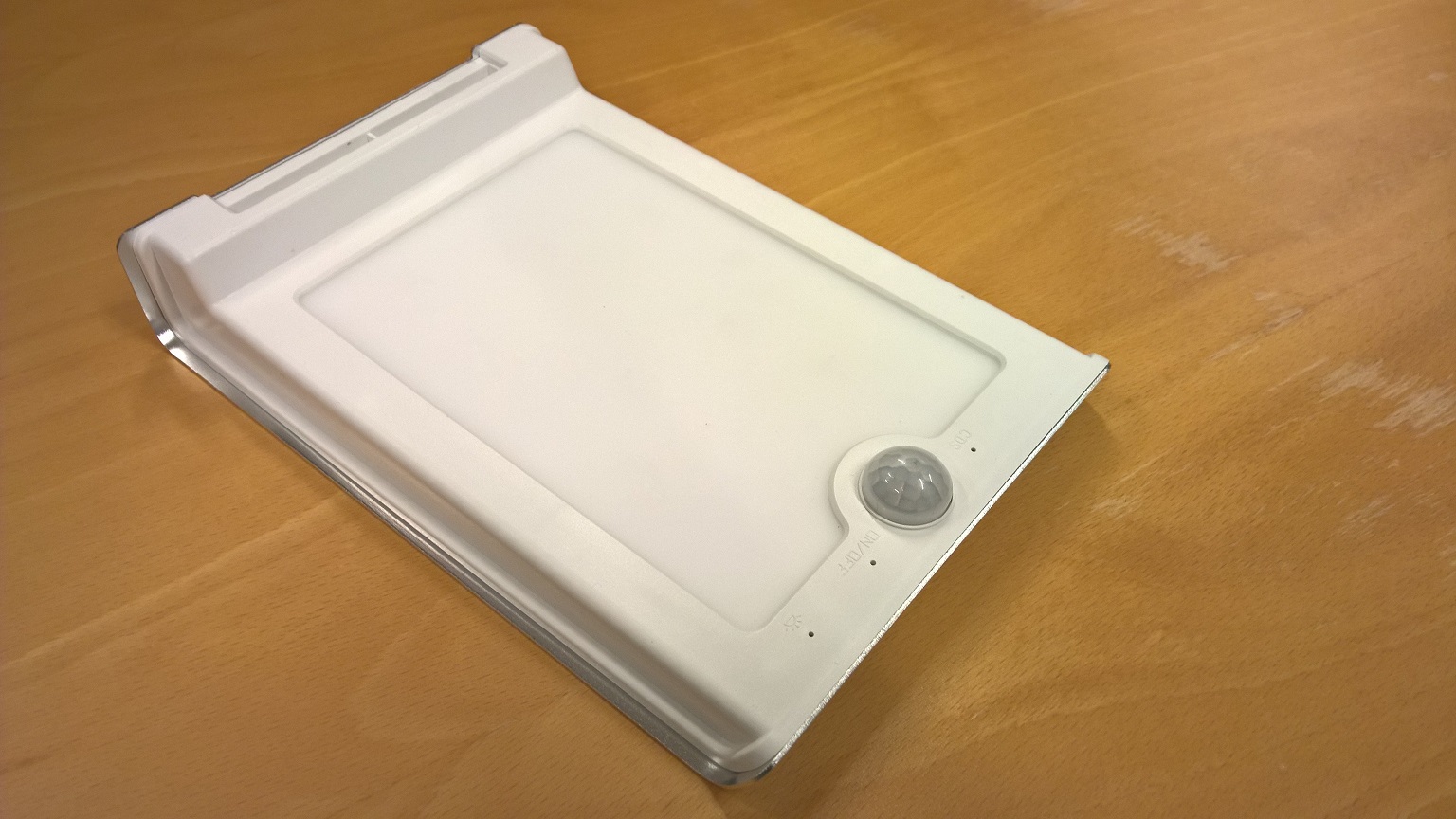
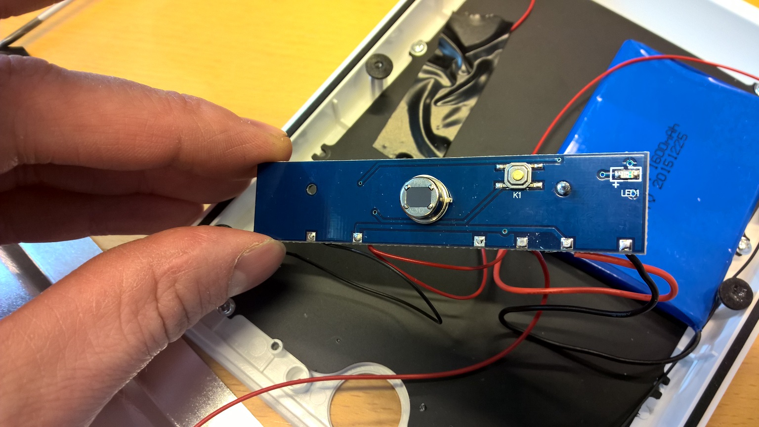
There is not much on the other side of the board, just a status LED, a button to turn it on and the PIR.
-
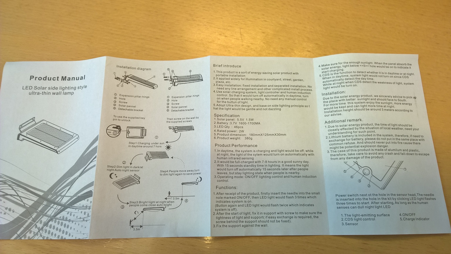
I'm sorry I did not test the device I just read the manual so I think that yes it has 2 modes for LED brightness.
@korttoma
Don't be sorry.I am not an circuits expert, I just try help you figure things out.
You wil have to test this lamp a little bit.
it looks that Q1 drives U1 active/not active when there is sun, but how/what turns on dimm lights in dark?Did you measure U1 pin 6 when pir active/not active?
-
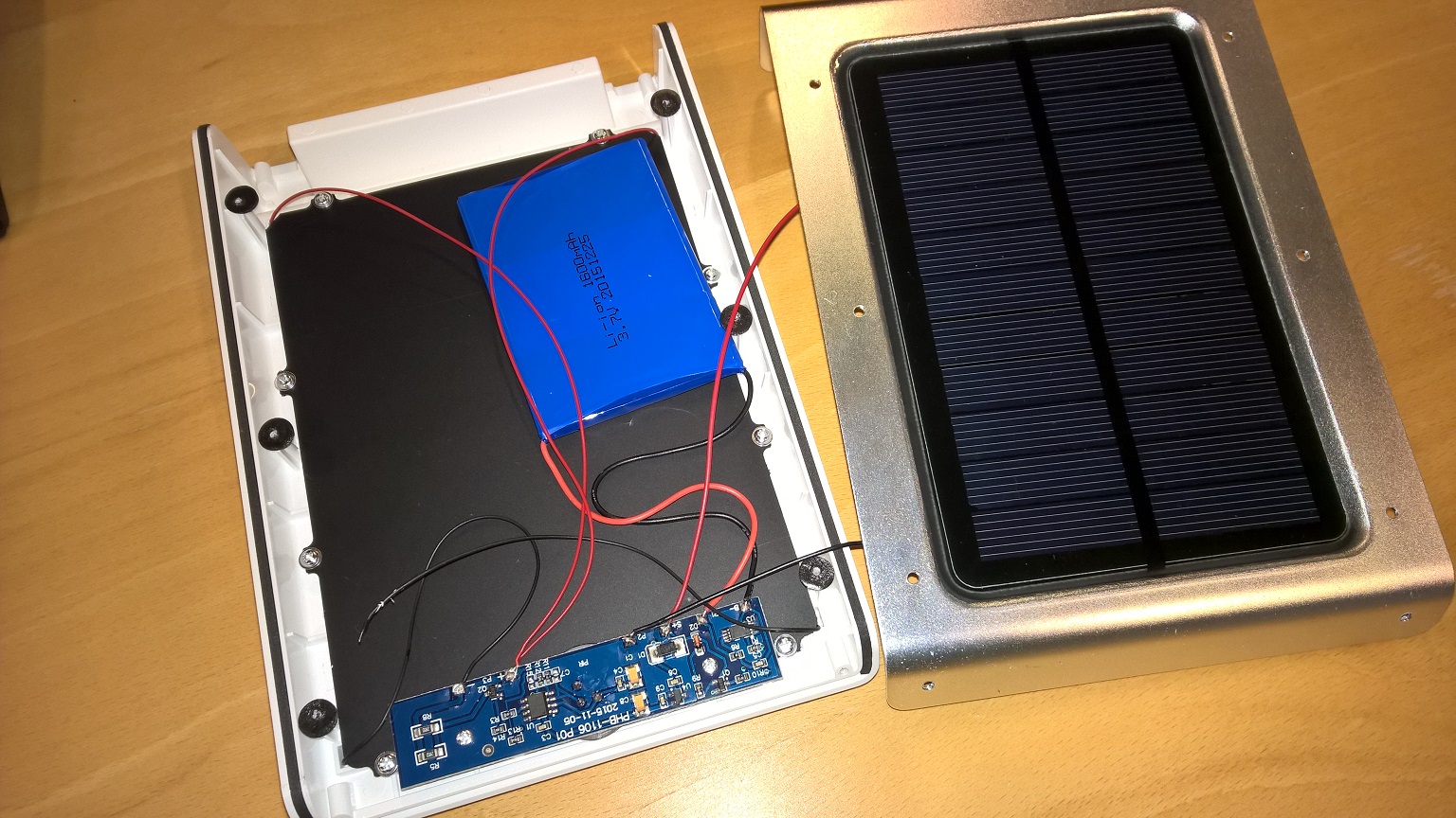
In the application I will use this one I actually do not care so much for the built in PIR and LED, I just see it as a smart enclosure with a solar battery power-supply built in. I will tap in to the 3.3V regulator to power a pro mini that has an external PIR and (LDR) Light sensor. In addition to this I would like to add voltage measurement for the battery. BTW, did you komplette your sketch? I would like to copy the battery voltage sensor part. I will look att figuring out the circuit later, it does not look to complicated.
- Tomas
-
In the application I will use this one I actually do not care so much for the built in PIR and LED, I just see it as a smart enclosure with a solar battery power-supply built in. I will tap in to the 3.3V regulator to power a pro mini that has an external PIR and (LDR) Light sensor. In addition to this I would like to add voltage measurement for the battery. BTW, did you komplette your sketch? I would like to copy the battery voltage sensor part. I will look att figuring out the circuit later, it does not look to complicated.
@korttoma
I did try some battery measurement variants. The following code works best for me. I suggest that you first try the following sketch.- measure the voltage with voltmeter on VCC pin and correct #define VREF value so it will be a close as possible to measured value before you integrate into case specific code
// define values for the battery measurement #define R1 1e6 #define R2 330e3 #define VMIN 2.8 #define VMAX 4.2 #define ADC_PRECISION 1023 #define VREF 1.13 int oldBatteryPcnt = 0; int batteryVoltage = 0; int BATTERY_SENSE_PIN = 0; int val = 0; void setup() { // use the 1.1 V internal reference #if defined(__AVR_ATmega2560__) analogReference(INTERNAL1V1); #else analogReference(INTERNAL); #endif Serial.begin(9600); } void loop() { //float batteryPcnt = getBatteryPercentage(); //val = analogRead(BATTERY_SENSE_PIN); //Serial.println(batteryVoltage); float batteryVoltage = getBatteryPercentage(); Serial.println(batteryVoltage); float batteryV= batteryVoltage; float batteryVmap = fabs(fmap(batteryV, 2.5, 4.2, 0.0, 1000.0)); int batteryPcnt = batteryVmap / 10; if (batteryPcnt >= 100) { batteryPcnt = 99; } Serial.print("Battery voltage: "); Serial.print(batteryPcnt); Serial.println(" %"); delay(2000); /*if (oldBatteryPcnt != batteryPcnt) { // Power up radio after sleep //gw.sendBatteryLevel(batteryPcnt); oldBatteryPcnt = batteryPcnt; }*/ // totally random test values } float getBatteryPercentage() { // read analog pin value int inputValue = analogRead(BATTERY_SENSE_PIN); // calculate the max possible value and therefore the range and steps float voltageDividerFactor = (R1 + R2) / R2; float maxValue = voltageDividerFactor * VREF; float voltsPerBit = maxValue / ADC_PRECISION; float batteryVoltage = voltsPerBit * inputValue; float batteryPercentage = ((batteryVoltage-VMIN)/(VMAX-VMIN))*100; //int batteryPercentage = map(batteryVoltage, 0, maxValue, 0, 100); //return batteryPercentage; return batteryVoltage; } float fmap(float x, float in_min, float in_max, float out_min, float out_max) { return (x - in_min) * (out_max - out_min) / (in_max - in_min) + out_min; } -
@gyro said:
int BATTERY_SENSE_PIN = 0;
This means that you use A0 for measuring right?
#define R1 1e6
#define R2 330e3And you have used 1Mohm and 330kohm for the resistors?
-
Thanks for the code and the additional info. Measuring the battery seems to work as expected but using the Internal reference seems to mess with the light level measurement LDR. Is it possible to use indifferent reference for different analog inputs? Or do I need to recalculate my LDR voltage divider?
-
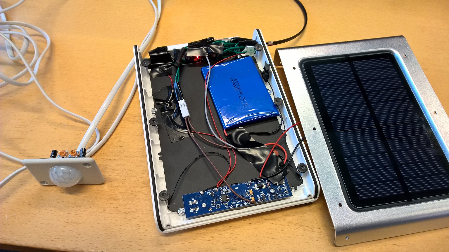
I managed to squeeze in a pro mini and radio that is now powered from the 3.3V available from the built in circuit board. It has battery voltage measurement, light level and a external PIR.
@korttoma great that you maneged to connect it lamp..
I don't know if analog reference is than set for all analog interfaces..
Just one more thing you should adjust:
I have figured out that I need to raise alarm for lower threshold for battery to higher than 3V (now is 2.5V!) because regulator voltage drop is ~250mV, and mini pro drops out at around 2.8V..
But the whole concept now works fairly good -
Hi,
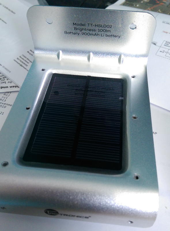
im waiting to my Chinese Lamps. So i ordered in the meantime one directly in Germany: TaoTronics Solar ...-16 LED (Model TT-HSL002)
https://www.amazon.de/gp/product/B00REDHZMW
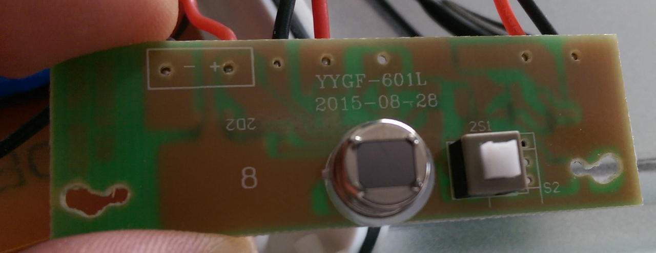
As you can see there is very different PCB. Do you have a hint for me if modification makes Sense ?
ed: now with external images:

Greetings
-
Hi,
im waiting to my Chinese Lamps. So i ordered in the meantime one directly in Germany: TaoTronics Solar ...-16 LED (Model TT-HSL002)
https://www.amazon.de/gp/product/B00REDHZMW
As you can see there is very different PCB. Do you have a hint for me if modification makes Sense ?
ed: now with external images:
Greetings
-
@ranseyer
This one looks is a little complicated. I think you should wait for china version :)
Take a picture of other side of circuit also.
Hello! It looks like you're interested in this conversation, but you don't have an account yet.
Getting fed up of having to scroll through the same posts each visit? When you register for an account, you'll always come back to exactly where you were before, and choose to be notified of new replies (either via email, or push notification). You'll also be able to save bookmarks and upvote posts to show your appreciation to other community members.
With your input, this post could be even better 💗
Register Login