In wall light switch node - Custom PCB
-
I have a problem finding the right wall switch. Normally they are all laid out for 230 volts, making them really big and requiring a lot of depth. Does anyone have experience with low voltage switches, which look nice and can be used for such projects ?
Thanks !@Sander-Teunissen, I have these running on a coin cell battery and the sizes for the overall board are: Height: 16mm, Width: 26mm, Length: 48mm. Please note that these sizes are that of the module without insulation. My current working node has its back covered with some fabric to stop it shorting out on the metal backbox. I need to come up with a solution for this. When i order my 3D Printer i'm hoping to fashion some sort of shielding for the rear.
-
I'm currently waiting on some more components to get this module up and running with thanks to @GertSanders providing the bootloader. All being well we will have it completed in the next month to be running with the radio and allowing ISP and FTDI/Serial uploads with the radio all connected.
Does anyone have any feature requests for this module other than simple battery monitoring?
-
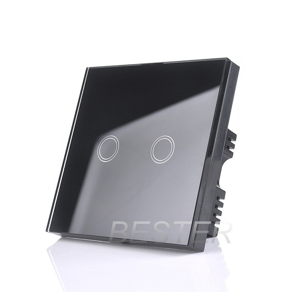
@jeylites, i was going to make a thread on these exact switches soon to discuss the possibility of interfacing them as they run on RF. Keep your eyes open for the thread asap ;).
I would like to make my own switch front with pressure capacitance at some point but thats for another day.
-
UPDATE - Feature upgrades
I have had the materials arrive to attempt to get the latest fixes sorted for this board. Hopefully this will allow us to serial upload while the radio is soldered permanently onto the board. I will update soon as i have attempted this. Keep you posted!
-
@jeylites, i was going to make a thread on these exact switches soon to discuss the possibility of interfacing them as they run on RF. Keep your eyes open for the thread asap ;).
I would like to make my own switch front with pressure capacitance at some point but thats for another day.
@Samuel235 said:
@jeylites, i was going to make a thread on these exact switches soon to discuss the possibility of interfacing them as they run on RF. Keep your eyes open for the thread asap ;).
I would like to make my own switch front with pressure capacitance at some point but thats for another day.
I didn't read this. interesting..one of my current project in progress is exactly this! Designing a special shield for glass plate etc :) the same for controlling one switch or more ;)
I have few Livolo that I have disassembled and looked how it works inside. but I'm not fan of 433mhz radio (or that would need some rflink). I'm actually trying to decidde the best way, if I want to hack it, or if I will do my own switch with glass plate I found. because I would like dimming, rfm69, authentication and my shield... -
@Samuel235 said:
@jeylites, i was going to make a thread on these exact switches soon to discuss the possibility of interfacing them as they run on RF. Keep your eyes open for the thread asap ;).
I would like to make my own switch front with pressure capacitance at some point but thats for another day.
I didn't read this. interesting..one of my current project in progress is exactly this! Designing a special shield for glass plate etc :) the same for controlling one switch or more ;)
I have few Livolo that I have disassembled and looked how it works inside. but I'm not fan of 433mhz radio (or that would need some rflink). I'm actually trying to decidde the best way, if I want to hack it, or if I will do my own switch with glass plate I found. because I would like dimming, rfm69, authentication and my shield...@scalz, If i'm honest I would like to see both. I love to see hacks being perfected, especially in products with such a clean finish as these but then again i also love seeing brand news products being brought to life. Either one you do, i'll be sure to support your ideas!
-
Having some very intermittent issues regarding uploading to this board using an FTDI adapter, 2 in fact. I have tried two adapters now and neither are giving me solid results. I have checked all solder joints and all seems fine. Time to start troubleshooting further. I'm uploading to this board using fuse settings of Low: E2 and High: DE, with a brownout detection point of 1v8. The error that i get 9/10 times is just that the programmer is out of sync. I will report back with my findings.
-
UPDATE
We have a working node. We're now able to serial upload and monitor the module with thanks to @GertSanders and his bootloader.
So the node currently has 2 switch inputs and that would be the maximum for the hardware interrupt, i may do some investigating to get another port for interrupt to enable us to have 3 switches on the one node.
Well, lets all thank the lead designer of the Optiboot boot loader: Bill Westfield !
Without his code and repository my compilations would not give any results. -
Well, lets all thank the lead designer of the Optiboot boot loader: Bill Westfield !
Without his code and repository my compilations would not give any results.@GertSanders, get him here and lets all buy him cake and beer!
-
For more than two switches see: http://www.gammon.com.au/forum/?id=11091
I would add a hardware debouncing (R/C) to avoid the problems mentioned in the article. -
For more than two switches see: http://www.gammon.com.au/forum/?id=11091
I would add a hardware debouncing (R/C) to avoid the problems mentioned in the article. -
For more than two switches see: http://www.gammon.com.au/forum/?id=11091
I would add a hardware debouncing (R/C) to avoid the problems mentioned in the article.@Xander said:
For more than two switches see: http://www.gammon.com.au/forum/?id=11091
I would add a hardware debouncing (R/C) to avoid the problems mentioned in the article.It's very good trick, but this circuit allows use of only tact switches. If you are interested - check my schematic (https://www.openhardware.io/view/102/Wall-Switch-Insertable-Node). It allows use of on\off switches too. I've drawn it after a little brainstorm :) I'm not sure it is optimal, but it works very nice.
-
@Xander said:
For more than two switches see: http://www.gammon.com.au/forum/?id=11091
I would add a hardware debouncing (R/C) to avoid the problems mentioned in the article.It's very good trick, but this circuit allows use of only tact switches. If you are interested - check my schematic (https://www.openhardware.io/view/102/Wall-Switch-Insertable-Node). It allows use of on\off switches too. I've drawn it after a little brainstorm :) I'm not sure it is optimal, but it works very nice.
-
@Koresh, thank you for linking me your module, i'm finally getting around to looking into some depth in this. First of all, i would like to ask something regarding the Exclusive-OR Gates;
I know how the gates work, in this case it uses Exclusive-OR (XOR) Gates, in simple terms, if the inputs are different the output will be HIGH, if the inputs are the same it will be LOW. The input you have connected to GND, could you tell me why that has to be connected to VCC with a resistor, could you not just connect that to GND?
I really like your use of the Schmitt Triggers here, makes the signal nice and sharp on the falling edges for the logic gates to work with.
Thanks!
-
We're currently working on locating the issue that we have with the light switch not being synced with OpenHab correctly. It works as intended but you have to double click to get the light on. We have located the issue lying within OpenHab's item configuration issues. Will post the resulting configuration needed to get this node working 100% perfectly.
-
Hi Samuel,
thanks for your great work.
I'm currently starting with my first steps in Home Automation.
I'm trying to control our lights in our flat. Our light switches are push switches with 12V. (dont know the right Translation to English. In German its called "Taster" - with no ON/OFF state, just a Push)Is this board useable for my switches? So can i connect the 12V to your board somehow and send the 12V "press button" to the main Fuse Box?
Thank you,
Arthur.
@artipi - As I'm not completely sure about the German wiring system I can't give you a answer that would be strictly abiding your rules. However, I will attempt to answer from my own personal opinion:
I'm not sure what you're sending the 12v back to the main fuse box for, this will simply send a 1/on or 0/off to your MySensors gateway. What you do with that signal is completely up to you. You could have a relay connected to mysensors gateway and then switch that relay with this light switch node. So, i suppose you could actually get a line on your fuse box switch with this but it would have to be sending signals to the gateway first, not directly to the fuse box.
Sorry if I haven't understood your intent correctly.
-
@artipi - As I'm not completely sure about the German wiring system I can't give you a answer that would be strictly abiding your rules. However, I will attempt to answer from my own personal opinion:
I'm not sure what you're sending the 12v back to the main fuse box for, this will simply send a 1/on or 0/off to your MySensors gateway. What you do with that signal is completely up to you. You could have a relay connected to mysensors gateway and then switch that relay with this light switch node. So, i suppose you could actually get a line on your fuse box switch with this but it would have to be sending signals to the gateway first, not directly to the fuse box.
Sorry if I haven't understood your intent correctly.
@Samuel235 - Thanks for the fast reaction:).
Ok, now i understand your switch node.
I think i need something with a 12V Relay. So i can send a command (ON/OFF) to a relay node that will act like my light switch.
Hello! It looks like you're interested in this conversation, but you don't have an account yet.
Getting fed up of having to scroll through the same posts each visit? When you register for an account, you'll always come back to exactly where you were before, and choose to be notified of new replies (either via email, or push notification). You'll also be able to save bookmarks and upvote posts to show your appreciation to other community members.
With your input, this post could be even better 💗
Register Login