Easy/Newbie PCB for MySensors
-
@nunver - great idea with the labels for voltage reg - that makes it more userfriendly! Will do.
Yes - REG should have a jumper connected. -
@shabba - Its a criteria of the MysX connector - to be able to switch RAW on/off from a daughter pcb. Nothing I have ever used and you dont have to think about it until you have a mother/daughter board.
Using RAW input and the internal regulator on the arduino you need to bypass the "REG" jumper and also the external voltage regulator if i remember right.
-
@sundberg84 :+1:
-
@sundberg84
Hey, I've been having a bit of trouble lately.
I've been trying to setup a node with your board which supports a PIR and a temp sensor (ds18b20).
Since there is a spot for a resistor on D3 on your board, I attached the temp sensor to that pin.
The PIR needs a pin that supports interrupts, so I connected that to D2.
Here is where the confusion starts.
If I read this page correctly, D2 is already in use for the radio.
I only checked it after I soldered everything together and found out my PIR doesn't work (it always sends a 1-signal).Any thoughts on this?
Is D2 really free for use on the board?Thanks!
-
@BastienVH - D2 is connected, but at this point not used by the radio (unless its been changed very recently). On the PCB its connected though - so if you want to use this I suggest you do not solder that pin (ie disconnect it) from the PCB and try.
If your PIR doesnt work you should start there... the cheap PIRS are very power sensitive (feed 5v not 3.3!! (you can modify this but standard is 5v!)) so check the connection with a multimeter. Try to connect only PIR and run a basic sketch to get that one to work. As you said you need to connect them to 2 or 3 if you want to use interrupt.
Add some serial.println to get info out whats happeing with the PIR.
@sundberg84
About D2: you mean I shouldn't solder the IRQ of the radio to the board?
I will try that next time.I've been testing the PIR with a nano and the 3.3V it supplies and that works fine.
If I take VCC or ground (or both) from the board with booster, the PIR starts acting up.
I guess I'll have to try some more if I want to get to the bottom of things. -
@BastienVH I have tried the normal china-pir (HC-SR501) on 3.3v and it does not work very well. I got random on/off or just strange behaivour. See specs! Voltage is 5V – 20V if you dont modify it (there are some threads on the forum).
The easiest way is to remove the pin for D2 on the arduino pinhead.
-
@sundberg84 Any idea why I've received a "2nd version" of your Rev.8 from PCBWay for free? By free I mean that I bought 10x your Rev.8 about 2 months ago (Black in the photo), but today I've got a package from China and when I opened I got that other PCB that I haven't ordered :confused:
I don't see any changes regarding the radio capacitor. Any clue?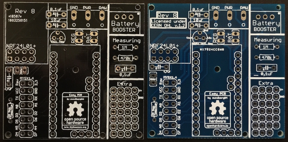
-
@danivalencia - sorry for late reply, I think @hek can help you. Give him a chat about this.
-
@danivalencia - sorry for late reply, I think @hek can help you. Give him a chat about this.
@sundberg84 No worry, I talked with hek and he finded that was a pcbway mistake. BTW...very good job with the PCB, I'm using it with a lot of my sensors :wink:
-
Hi there !
@sundberg84 very nice job ! :)
is there any plan to fit the board for the Arduino Nano (5V) ? -
@Lior-Rubin - Not at this point.
What would be the benefits compared to Pro Mini?
Nano can only handle 5v input and not 3.3.Controller: Proxmox VM - Home Assistant
MySensors GW: Arduino Uno - W5100 Ethernet, Gw Shield Nrf24l01+ 2,4Ghz
MySensors GW: Arduino Uno - Gw Shield RFM69, 433mhz
RFLink GW - Arduino Mega + RFLink Shield, 433mhz -
@Lior-Rubin - Not at this point.
What would be the benefits compared to Pro Mini?
Nano can only handle 5v input and not 3.3.@sundberg84 Nothing special behalf of the face that it easier to program it (it has mini USB onboard).
-
@Lior-Rubin Yes - you are right, the Nano is easier.
But I want to stick with the pro mini and the advantages with both a 3.3 and a 5v version for both battery operations and regulated power. You are free if you like to modify my design to your wish and add a Nano instead. If you need any help just ask!Controller: Proxmox VM - Home Assistant
MySensors GW: Arduino Uno - W5100 Ethernet, Gw Shield Nrf24l01+ 2,4Ghz
MySensors GW: Arduino Uno - Gw Shield RFM69, 433mhz
RFLink GW - Arduino Mega + RFLink Shield, 433mhz -
@Lior-Rubin Yes - you are right, the Nano is easier.
But I want to stick with the pro mini and the advantages with both a 3.3 and a 5v version for both battery operations and regulated power. You are free if you like to modify my design to your wish and add a Nano instead. If you need any help just ask!@sundberg84 Thanks, I'll try to play with the Pro Mini :)
BTW - can you recommend for good supplier from eBay\AliExpress\Etc. ? -
@Lior-Rubin - For components i pretty much use the links from www.mysensors.com/store
Dont forget to order a fdti programmer :)Controller: Proxmox VM - Home Assistant
MySensors GW: Arduino Uno - W5100 Ethernet, Gw Shield Nrf24l01+ 2,4Ghz
MySensors GW: Arduino Uno - Gw Shield RFM69, 433mhz
RFLink GW - Arduino Mega + RFLink Shield, 433mhz -
@Lior-Rubin - For components i pretty much use the links from www.mysensors.com/store
Dont forget to order a fdti programmer :)@sundberg84 I have all these ... I meant for the Pro Mini 3.3V that you used in your design.
I ordered some from Chinese supplier but the board was damaged ( cannot upload sketches to them).where did you get yours ?
-
@Lior-Rubin - 3 batches from china, link in mysensor store - worked great for me.
Hello! It looks like you're interested in this conversation, but you don't have an account yet.
Getting fed up of having to scroll through the same posts each visit? When you register for an account, you'll always come back to exactly where you were before, and choose to be notified of new replies (either via email, or push notification). You'll also be able to save bookmarks and upvote posts to show your appreciation to other community members.
With your input, this post could be even better 💗
Register Login