DIY Blind Control Motor
-
Pretty cool, would it be possible to get a video with audio of the final 'product'?
-
@ServiceXp said:
Pretty cool, would it be possible to get a video with audio of the final 'product'?
Sure! This is with eighth steps - and it seems to be as fast as the motor will go without reducing the microsteps.
-
@ServiceXp said:
Pretty cool, would it be possible to get a video with audio of the final 'product'?
Sure! This is with eighth steps - and it seems to be as fast as the motor will go without reducing the microsteps.
-
@ServiceXp said:
Pretty cool, would it be possible to get a video with audio of the final 'product'?
Sure! This is with eighth steps - and it seems to be as fast as the motor will go without reducing the microsteps.
-
@ServiceXp
A few things I should mention for anyone trying to undertake this project:
-I'm assuming that the choice of stepper motor is important to control noise. It is possible that a different stepper would give an improved speed/noise ratio.
-One of the most important factor in reducing noise is ensuring there is no hard surface for the motor to 'rumble' on. This is especially bad when using full stepping - the motor rumbles like crazy. The more microsteps, the less rumble and the less noise.
-I coated the sprocket and bracket in silicon caulking to reduce noise, it seemed to help a little, but was nothing compared to reducing the microsteps
-If you are looking to have the best of both worlds, you can add some code as follows in order to choose the microsteps based on the desired RPM. This way you can control the speed via vera and the arduino will actively choose the best microstepping mode. The regular EasyDriver has similar pins, but I believe the most microsteps is 8 and there are only two pins to control
-I am using a 8Mhz 3.3V APM and it may be possible to increase the steps/second if you use a more powerful processor (for example, 16Mhz APM) - I will test it with a nano when I get a chance. @hek, the nano used for the gateway is 16Mhz, correct? It says 16M on the eBay page but I just wanted to confirm.void newnMicroSteps(){ if(nMicroSteps==1){ digitalWrite(MS1pin,LOW); digitalWrite(MS2pin,LOW); digitalWrite(MS3pin,LOW); } if(nMicroSteps==2){ digitalWrite(MS1pin,HIGH); digitalWrite(MS2pin,LOW); digitalWrite(MS3pin,LOW); } if(nMicroSteps==4){ digitalWrite(MS1pin,LOW); digitalWrite(MS2pin,HIGH); digitalWrite(MS3pin,LOW); } if(nMicroSteps==8){ digitalWrite(MS1pin,HIGH); digitalWrite(MS2pin,HIGH); digitalWrite(MS3pin,LOW); } if(nMicroSteps==16){ digitalWrite(MS1pin,HIGH); digitalWrite(MS2pin,HIGH); digitalWrite(MS3pin,HIGH); } maxStepperSpeed = maxRPM/60*stepsPerRev*nMicroSteps; fullOpenSteps = fullOpenRevs*stepsPerRev*nMicroSteps; maxStepperAccel = maxAccelRPMPM/60*stepsPerRev*nMicroSteps; stepper1.setMaxSpeed(maxStepperSpeed); stepper1.setAcceleration(maxStepperAccel); }Edit: I just noticed that I calculated acceleration wrong. Here is the correct equation:
maxStepperAccel = maxAccelRPMPM/60/60*stepsPerRev*nMicroSteps; -
@ServiceXp
Note: I tried the 16Mhz Arduino Nano and I seem to be able to get much higher speeds with high microstepping. I have almost silent operation with 8 microsteps and the blinds open in about 10 seconds. I assume if you get an even faster processor you can step it even more quickly.
-
For the next part of my project I'm looking to have two interlocking gears which grab and pull the string in order to slide the vines of the blinds to one side.
I can attach one gear to the servo, but the other gear would require some sort of bearing? Does anyone have any idea what type of bearing I can use? If there's a name I can search for them on eBay (I assume they are available there).
-
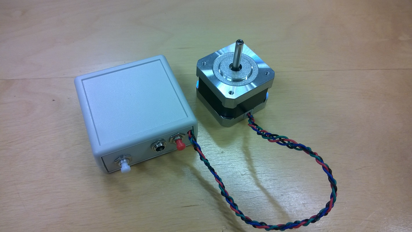
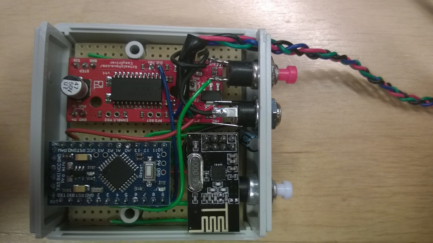
I really did not put much thought in to the physical setup, I just squeezed it in to as small a box I could. Here is some pictures. Still waiting for some parts to get it mounted.
I forgot to mention that the "sleep" pin of the driver board is also connected to the arduino to enable the motor to spin freely when it is not being controlled from the arduino. I want it to be possible to use the original cord to open/close the blinds also (WAF).
@korttoma , did you ever try using the accelstepper run() command instead of runToPosition(). From my understanding the run() command is non-blocking and you put it in your main-loop. That way, if Vera sends a new commands you can set it to stop immediately using:
stop();
runToPosition();
I gave it a shot and the motor didn't seem to move at all - I'm not sure if you ever experimented with it, thought I'd ask.
-
@korttoma , did you ever try using the accelstepper run() command instead of runToPosition(). From my understanding the run() command is non-blocking and you put it in your main-loop. That way, if Vera sends a new commands you can set it to stop immediately using:
stop();
runToPosition();
I gave it a shot and the motor didn't seem to move at all - I'm not sure if you ever experimented with it, thought I'd ask.
Sorry, I have not experimented with other functions than the once I have in my current sketch since it is working according to my needs except for the problem with position updates to Vera I'm having.
I guess some people would like it if it was possible to use up/down/stop if it is possible with the run() function but I have schedules running my blinds 95% of the time.
I managed to workaround the position updates to vera problem by using the up/down instead of open/close, I will look in to it when I find some time and then I could check out the run() function too. -
Sorry, I have not experimented with other functions than the once I have in my current sketch since it is working according to my needs except for the problem with position updates to Vera I'm having.
I guess some people would like it if it was possible to use up/down/stop if it is possible with the run() function but I have schedules running my blinds 95% of the time.
I managed to workaround the position updates to vera problem by using the up/down instead of open/close, I will look in to it when I find some time and then I could check out the run() function too.I don't know what I was doing wrong before, but I got the non-block run feature working with your code. I have my blinds controlled by XBMC as well, so if I start and stop a movie in quick succession, I want to make sure the blinds end up in the right spot. I've attached the relevant snippets of code below
void loop(){

 if (gw.messageAvailable()) {
  //Serial.print("New message from GW");
  // ot new messsage from gw
  message_s message = gw.getMessage();
  setRelayStatus(message);
}

stepper1.run();
}
and then when you get the message:
if (message.header.type==V_DIMMER) { // float IncomingControl = atoi(message.data); //Serial.print("Message: "); //Serial.println(IncomingControl); //Serial.println((100-IncomingControl)/100*-1*fullOpenSteps); delay(5); float incomingNewPosition = (100-IncomingControl)/100*-1*fullOpenSteps; stepper1.stop(); stepper1.runToPosition(); stepper1.moveTo(incomingNewPosition); int IncomingControlSend = IncomingControl; gw.sendVariable(CHILD_ID, V_DIMMER, IncomingControlSend); } -
Yes, it is possible! You have a couple of options.
##Poll configuration data from node
- Select one of V_VAR1, V_VAR2, V_VAR3, V_VAR4, V_VAR5 to use for your configuration;
choose from your root or child nodes. You can use all five parameters per each of your root and child device. It is up to you how to design this; - Program your sketch to fetch variable from vera using gw.request(). You will have to take care to get reply later by yourself using in your callback method initialized in gw.setup(). See RelayActuator sketch for an example on how to handle incoming messages.
- First run of your modified sketch to request parameters. Be prepared that you will receive an empty string because at this time we have just created empty variables at vera side;
- Refresh your vera and go to particular child into Advanced Tab. You should be able to see your new variables named Variable1...Variable5. Variable1 corresponds to V_VAR1 inside your sketch etc.;
fill free to change empty field on vera side to the value your needed, Save changes;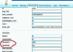
- Check with you Arduino, it should receive correct data at this point;
- You free to use whatever design you want. You can pull/request data at each start of you node or you can pull each 30 minutes like many z-wave devices do if they operate from battery. Other example can be if you need for your to nodes to communicate to each other and you need to tell a radio ID to one/both nodes to establish their communication. But for this one you probably want to use Push...
##Push configuration data from Vera to node
Example: You need to push data from vera on event or using schedule and it should be initiated instantly by vera, not by node. For example you want your clock to show external temperature received by vera from the Weather plugin or from other sensor.
-
Choose from V_VAR1, V_VAR2, V_VAR3, V_VAR4, V_VAR5 to be used for data push
-
Design your sketch to listen for incoming messages with desired variable. See RelayActuator for an example on how to handle incoming data.
-
Create a new scene on vera side. The scene should be run according to your goal. For example each 10 minutes;
-
Use Lua tab while editing scene to provide data for the push. For example this Lua is taking current temperature from Weather (vera id = 61) plugin and pushing it to the node (vera id for root device = 372) using VAR_5:
local temp = luup.variable_get("urn:upnp-org:serviceId:TemperatureSensor1","CurrentTemperature", 61)
temp = temp*10.0
luup.call_action("urn:upnp-arduino-cc:serviceId:arduino1", "SendCommand", {radioId="4;255", variableId="VAR_5", value=temp}, 372)
SendCommand will push a message to your node. You can also call it with static values (without programming) using the Advanced tab in the scene editor.
(This post was updated to 1.4 from from @axillent old tips page on micasaverde)
@hek said:
Yes, it is possible! You have a couple of options.
##Poll configuration data from node
- Select one of V_VAR1, V_VAR2, V_VAR3, V_VAR4, V_VAR5 to use for your configuration;
choose from your root or child nodes. You can use all five parameters per each of your root and child device. It is up to you how to design this; - Program your sketch to fetch variable from vera using gw.request(). You will have to take care to get reply later by yourself using in your callback method initialized in gw.setup(). See RelayActuator sketch for an example on how to handle incoming messages.
- First run of your modified sketch to request parameters. Be prepared that you will receive an empty string because at this time we have just created empty variables at vera side;
- Refresh your vera and go to particular child into Advanced Tab. You should be able to see your new variables named Variable1...Variable5. Variable1 corresponds to V_VAR1 inside your sketch etc.;
fill free to change empty field on vera side to the value your needed, Save changes; - Check with you Arduino, it should receive correct data at this point;
- You free to use whatever design you want. You can pull/request data at each start of you node or you can pull each 30 minutes like many z-wave devices do if they operate from battery. Other example can be if you need for your to nodes to communicate to each other and you need to tell a radio ID to one/both nodes to establish their communication. But for this one you probably want to use Push...
##Push configuration data from Vera to node
Example: You need to push data from vera on event or using schedule and it should be initiated instantly by vera, not by node. For example you want your clock to show external temperature received by vera from the Weather plugin or from other sensor.
-
Choose from V_VAR1, V_VAR2, V_VAR3, V_VAR4, V_VAR5 to be used for data push
-
Design your sketch to listen for incoming messages with desired variable. See RelayActuator for an example on how to handle incoming data.
-
Create a new scene on vera side. The scene should be run according to your goal. For example each 10 minutes;
-
Use Lua tab while editing scene to provide data for the push. For example this Lua is taking current temperature from Weather (vera id = 61) plugin and pushing it to the node (vera id for root device = 372) using VAR_5:
local temp = luup.variable_get("urn:upnp-org:serviceId:TemperatureSensor1","CurrentTemperature", 61)
temp = temp*10.0
luup.call_action("urn:upnp-arduino-cc:serviceId:arduino1", "SendCommand", {radioId="4;255", variableId="VAR_5", value=temp}, 372)
SendCommand will push a message to your node. You can also call it with static values (without programming) using the Advanced tab in the scene editor.
(This post was updated to 1.4 from from @axillent old tips page on micasaverde)
I'm moving on to add another stepper and I need a few more custom variables (4) - is there any way to add new variables? Or is he maximum 5?
- Select one of V_VAR1, V_VAR2, V_VAR3, V_VAR4, V_VAR5 to use for your configuration;
-
@hek said:
Yes, it is possible! You have a couple of options.
##Poll configuration data from node
- Select one of V_VAR1, V_VAR2, V_VAR3, V_VAR4, V_VAR5 to use for your configuration;
choose from your root or child nodes. You can use all five parameters per each of your root and child device. It is up to you how to design this; - Program your sketch to fetch variable from vera using gw.request(). You will have to take care to get reply later by yourself using in your callback method initialized in gw.setup(). See RelayActuator sketch for an example on how to handle incoming messages.
- First run of your modified sketch to request parameters. Be prepared that you will receive an empty string because at this time we have just created empty variables at vera side;
- Refresh your vera and go to particular child into Advanced Tab. You should be able to see your new variables named Variable1...Variable5. Variable1 corresponds to V_VAR1 inside your sketch etc.;
fill free to change empty field on vera side to the value your needed, Save changes; - Check with you Arduino, it should receive correct data at this point;
- You free to use whatever design you want. You can pull/request data at each start of you node or you can pull each 30 minutes like many z-wave devices do if they operate from battery. Other example can be if you need for your to nodes to communicate to each other and you need to tell a radio ID to one/both nodes to establish their communication. But for this one you probably want to use Push...
##Push configuration data from Vera to node
Example: You need to push data from vera on event or using schedule and it should be initiated instantly by vera, not by node. For example you want your clock to show external temperature received by vera from the Weather plugin or from other sensor.
-
Choose from V_VAR1, V_VAR2, V_VAR3, V_VAR4, V_VAR5 to be used for data push
-
Design your sketch to listen for incoming messages with desired variable. See RelayActuator for an example on how to handle incoming data.
-
Create a new scene on vera side. The scene should be run according to your goal. For example each 10 minutes;
-
Use Lua tab while editing scene to provide data for the push. For example this Lua is taking current temperature from Weather (vera id = 61) plugin and pushing it to the node (vera id for root device = 372) using VAR_5:
local temp = luup.variable_get("urn:upnp-org:serviceId:TemperatureSensor1","CurrentTemperature", 61)
temp = temp*10.0
luup.call_action("urn:upnp-arduino-cc:serviceId:arduino1", "SendCommand", {radioId="4;255", variableId="VAR_5", value=temp}, 372)
SendCommand will push a message to your node. You can also call it with static values (without programming) using the Advanced tab in the scene editor.
(This post was updated to 1.4 from from @axillent old tips page on micasaverde)
I'm moving on to add another stepper and I need a few more custom variables (4) - is there any way to add new variables? Or is he maximum 5?
@naveen said:
I'm moving on to add another stepper and I need a few more custom variables (4) - is there any way to add new variables? Or is he maximum 5?
If you add another stepper to a node you will add another window cover device in Vera right? So shouldn't there be 5 more Variables for this new device right?
- Select one of V_VAR1, V_VAR2, V_VAR3, V_VAR4, V_VAR5 to use for your configuration;
-
@naveen said:
I'm moving on to add another stepper and I need a few more custom variables (4) - is there any way to add new variables? Or is he maximum 5?
If you add another stepper to a node you will add another window cover device in Vera right? So shouldn't there be 5 more Variables for this new device right?
@korttoma said:
@naveen said:
I'm moving on to add another stepper and I need a few more custom variables (4) - is there any way to add new variables? Or is he maximum 5?
If you add another stepper to a node you will add another window cover device in Vera right? So shouldn't there be 5 more Variables for this new device right?
I wasn't planning on adding another device. I was planning on implementing the UP/DOWN functionality to control the sliding of the vertical blinds. While the V_DIMMER slider would control the 'tilt'
-
Ahh, I see. Maybe it is an option for you to add another (dummy) device of some type just to get more variables.
-
Ahh, I see. Maybe it is an option for you to add another (dummy) device of some type just to get more variables.
-
Old thread, but is it possible to clean up enough to make a tutorial on this? All the info is quite confusing to a person who's not as good as you guys :-)
Is it also possible to adapt this method into making a door lock? -
Finally finished my setup, here is a picture. Works pretty well, it is slightly louder than I would have hoped but if you run it at 1/16th microsteps its almost silent. The only issue is that it won't run very fast at 1/16 microsteps.
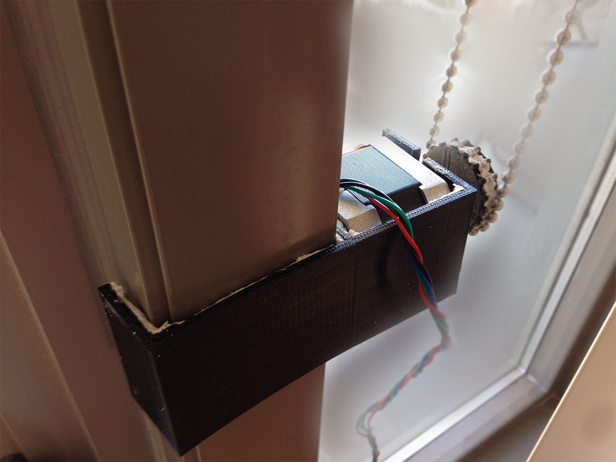
@naveen said in DIY Blind Control Motor:
Finally finished my setup, here is a picture. Works pretty well, it is slightly louder than I would have hoped but if you run it at 1/16th microsteps its almost silent. The only issue is that it won't run very fast at 1/16 microsteps.
Sorry, I know this topic is quite old, but where did you get that wheel (that translates motor force to the chain)? I was thinking about building something similar and thats my main problem.
Looks 3D printed as well as the holder (I really have to get a 3D printer ;) )..
Hello! It looks like you're interested in this conversation, but you don't have an account yet.
Getting fed up of having to scroll through the same posts each visit? When you register for an account, you'll always come back to exactly where you were before, and choose to be notified of new replies (either via email, or push notification). You'll also be able to save bookmarks and upvote posts to show your appreciation to other community members.
With your input, this post could be even better 💗
Register Login