Problem with RFM69 on homemade board
-
Hello there,
I recently build PCB board for mysensor node with Atmega328P. Microcontroller is working great with no problem. But there is no connection to RFM module. I have tried to debugg in on my own and get to this that is stucking on this line:
do writeReg(REG_SYNCVALUE1, 0xaa); while (readReg(REG_SYNCVALUE1) != 0xaa)And nothing happens next. No serial communication, nothing. What can be the problem? I checked connections between the micro and RFM69 and everything seems okay.
It's connected of course through level converter to get 3.3V (but I have to say that accidentaly I connected if for 1-2 minutes to 5V pins - But I don't know - it could cause my rfm module break?).
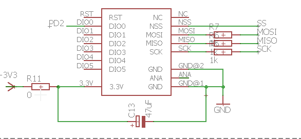
I also attached schematic of my connection.
Thank your for help. I am fighting with that for last 3 days :(
-
Hello there,
I recently build PCB board for mysensor node with Atmega328P. Microcontroller is working great with no problem. But there is no connection to RFM module. I have tried to debugg in on my own and get to this that is stucking on this line:
do writeReg(REG_SYNCVALUE1, 0xaa); while (readReg(REG_SYNCVALUE1) != 0xaa)And nothing happens next. No serial communication, nothing. What can be the problem? I checked connections between the micro and RFM69 and everything seems okay.
It's connected of course through level converter to get 3.3V (but I have to say that accidentaly I connected if for 1-2 minutes to 5V pins - But I don't know - it could cause my rfm module break?).
I also attached schematic of my connection.
Thank your for help. I am fighting with that for last 3 days :(
@voximdo I;m not sure how well the RFM69 handles the 5V. I do know that the NRF doesn't like that, I fried one of those one time ;-).
I know it doesn't sound tempting. But replacing the RFM with a new one might be the best solution. Unless someone else can help you with this.
-
@voximdo
you don't give enough details...- your board: what looks like your level converter? on your schematic we don't see it. Is it your 1K res ??? if so, that's not a level converter! and you can't use a voltage regulator for this. you need to use mosfets.
- which arduino board are you using for your tests? if uno/nano, atmel is powered through 5v, so dataline would be all 5v. The 16mhz crystal is a good indicator when you're not sure ;)
I always try to power my circuit with 3v if rfm69. and if 5v, there are booster or charge pump.. Like this, it's easier to handle because there are much more things working at 3v than 5v, and then if you need level converter for each, pain begins.
but in case, about level converter : https://www.sparkfun.com/products/12009
-
I don't have level converter on my board, I forget about it, so I connected it outside the board. So MOSI, MISO, SCK and NSS goes to level converter and then to Atmega328p which is powered with 5V. Exactly that one from your link.
I am using Arduino UNO board for testing. I am powering circuit with 5V because I don't have any programmer (only Arduino board). So RX/TX for communication and programming have also 5V.
-
I didn't have pullup, but I don't have any more SPI decives also. But still - I added it as you sugested and still the same.
I have also one node which is working (Arduino PRO Mini connected with RFM69 module. And I tried test radio module also with that code:
https://learn.adafruit.com/adafruit-rfm69hcw-and-rfm96-rfm95-rfm98-lora-packet-padio-breakouts/rfm69-test. I used working node as transmitter and my homemade board as receiver.And instead of "Hello World" I am getting some trash data:
@voximdo I think you're only receiving ones over the spi interface, hence the 255 rssi values. Maybe you swapped mosi & miso signals (edit: seems ok in your schematics)
Do you have a scope or logic analyzer you can attach to the spi bus to check correct functioning? -
I could borrow scope for the weekend. Could you tell me what should I searching for in this signals?
@voximdo the ss line (normally high) should go low when the avr is talking to the rfm.
The clk signal is the clock from the avr to the rfm, to trigger exchange of bits.
Miso is data going from rfm to avr, mosi is data in the other direction.
You could trace the data from the startup of mysensors, until the check on which it fails and see what happens.
There's not much more I can do as I don't have an rfm setup...
Hello! It looks like you're interested in this conversation, but you don't have an account yet.
Getting fed up of having to scroll through the same posts each visit? When you register for an account, you'll always come back to exactly where you were before, and choose to be notified of new replies (either via email, or push notification). You'll also be able to save bookmarks and upvote posts to show your appreciation to other community members.
With your input, this post could be even better 💗
Register Login