HC-SR501 motion sensor
-
-
I want to interface HC-SR501 to my renesas controller..is it possible??????????????they mentioned somewhere for arduino only...thatsy doubt..reply fast
-
Does anybody who has bypassed the onboard regulator on the HC-SR501 be able to post up a photo of where you soldered?
I thought it was pretty simple and soldered my 3.3V lead to the leg on the 7133. It seems to power up (at least, so says my voltmeter), but the trigger (output) pin just goes high immediately and never changes. So on my sensors network it is just constantly triggering (even when there's no motion).
I'm doing something wrong, but not sure what it is. Any hints?
@Bandra said:
Does anybody who has bypassed the onboard regulator on the HC-SR501 be able to post up a photo of where you soldered?
I thought it was pretty simple and soldered my 3.3V lead to the leg on the 7133. It seems to power up (at least, so says my voltmeter), but the trigger (output) pin just goes high immediately and never changes. So on my sensors network it is just constantly triggering (even when there's no motion).
I'm doing something wrong, but not sure what it is. Any hints?
@Bandra , have you found any answers to your question? I have exactly the same problem, the output of the sensor goes straight to High, moving the potentiometers sometimes causes it to go Low but not in a stable state, goes low, you trigger it and goes high and stays this way... Maybe the sensor is on his way out... right now I don't have another one to test with.
-
Here is what I did...
Removed the regulator and the diode. Jumpered from the anode of the diode to the location of the output of the 3v3 regulator. Works perfectly, and I can still utilize the original power supply pin! (good for using a standard 3 pin female header, no messy wires). Oh, and make sure your 3v3 power source is clean; boosters are notorious for having significant noise on top of the DC.
-
Thank you for your answer. This was not the problem in my case. Long story short, I made a multisensor node for testing on an Arduino Uno and everything went well, the problems started when I moved to Pro Mini 5V version. I only use 3.3V for the radio, all of the other sensors of this node are 5V. The power was not the issue as I used on both Uno and Pro Mini battery power for testing. I moved the sensor back to the Uno setup (used for two weeks for testing) and still was not working. Moved the potentiometer for the Sensibility to the minimum and then I saw random good readings so arrived to the conclusion that there could be some problem with this.
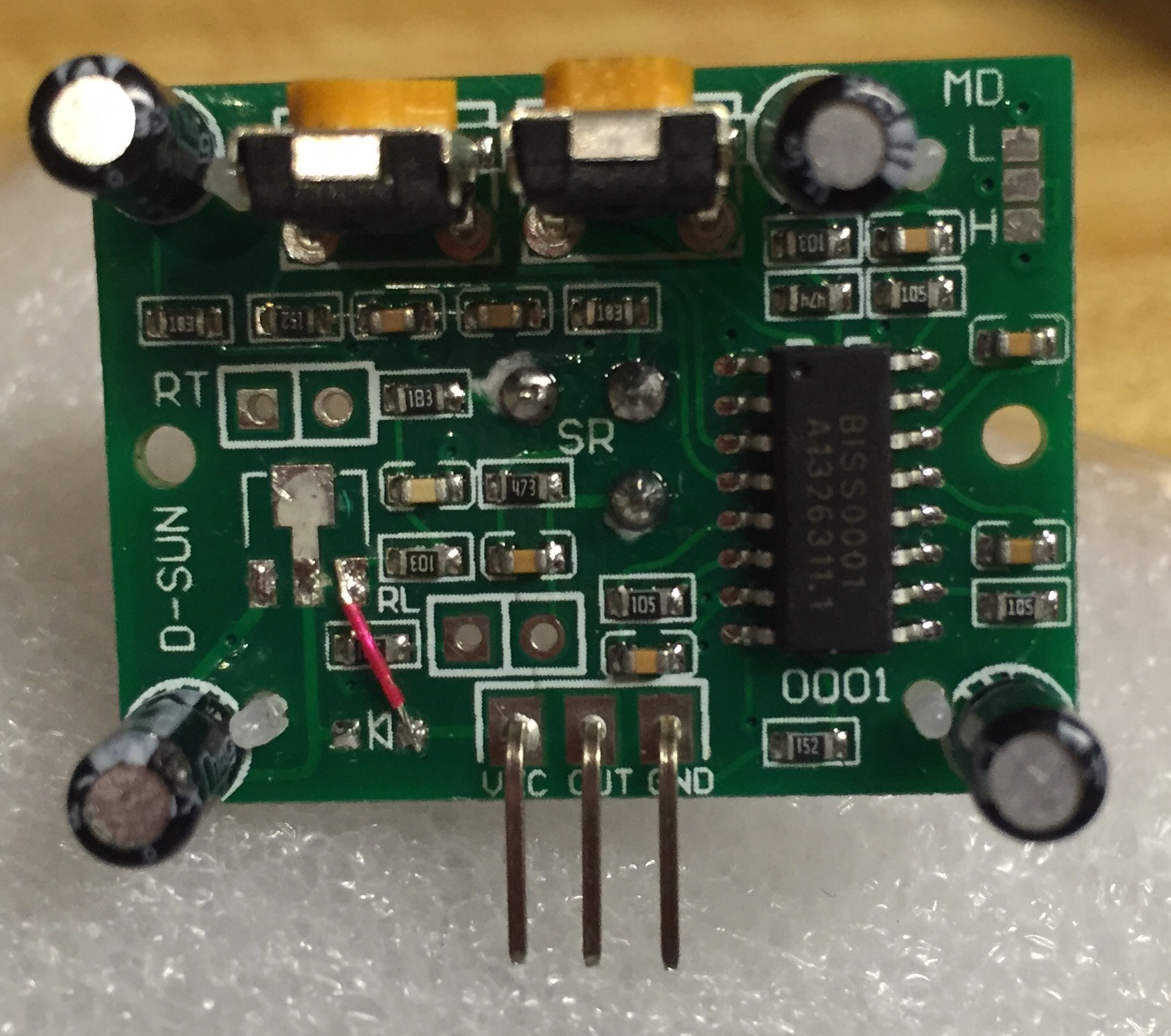
After some searching I found that my Pir had 105 potentiometer both for Sensibility and Time, and in the schematics there is a 104 for Sensibility and 105 for Time, that's why the sensibility worked only the first mm of the rotation. Searched home but unfortunatly the bigest one I had was 10k and not 100k, put it for testing, pump it to the max and is working like a charm. I will try with 100k as soon as I will get some.
![IMG_0659[2].jpg](/uploads/upload-48d8a3dd-4cfe-44c8-a82b-3a785082c4d0.jpg)
This is a picture with the sensor, mine had 105 on both that's why it was so hard to set. Now the multisensor is in a beautifull case, working and looking smart :). -
Here is what I did...
Removed the regulator and the diode. Jumpered from the anode of the diode to the location of the output of the 3v3 regulator. Works perfectly, and I can still utilize the original power supply pin! (good for using a standard 3 pin female header, no messy wires). Oh, and make sure your 3v3 power source is clean; boosters are notorious for having significant noise on top of the DC.
-
Thank you for your answer. This was not the problem in my case. Long story short, I made a multisensor node for testing on an Arduino Uno and everything went well, the problems started when I moved to Pro Mini 5V version. I only use 3.3V for the radio, all of the other sensors of this node are 5V. The power was not the issue as I used on both Uno and Pro Mini battery power for testing. I moved the sensor back to the Uno setup (used for two weeks for testing) and still was not working. Moved the potentiometer for the Sensibility to the minimum and then I saw random good readings so arrived to the conclusion that there could be some problem with this.
After some searching I found that my Pir had 105 potentiometer both for Sensibility and Time, and in the schematics there is a 104 for Sensibility and 105 for Time, that's why the sensibility worked only the first mm of the rotation. Searched home but unfortunatly the bigest one I had was 10k and not 100k, put it for testing, pump it to the max and is working like a charm. I will try with 100k as soon as I will get some.
This is a picture with the sensor, mine had 105 on both that's why it was so hard to set. Now the multisensor is in a beautifull case, working and looking smart :).@adrianmihai83 Hey. Did the potentiometer change solved it for good? I've had some issues with the HC-SR501 where it would constantly change from high to low.
I have one that has been working great for some months. Today I've made a simple update to the sketch (via OTA, so no physical contact), and now the sensor keeps triggering constantly. It was not a change in the sketch that caused this, I'm sure of that.
I've reduced the sensitivity and it seems to have stopped now... Still, it is weird because it was working before, with that same sensitivity level! -
I've heard that these PIR sensors can get very sensitive when the battery level drops, so it's worth checking the status of those batteries or better yet, trying some new ones.
Hello! It looks like you're interested in this conversation, but you don't have an account yet.
Getting fed up of having to scroll through the same posts each visit? When you register for an account, you'll always come back to exactly where you were before, and choose to be notified of new replies (either via email, or push notification). You'll also be able to save bookmarks and upvote posts to show your appreciation to other community members.
With your input, this post could be even better 💗
Register Login