livolo Glass Panel Touch Light Wall Switch + arduino 433Mhz
-
@Samuel235 stop looking in my mind :) I have already some working proto though for the plate pcb ;) but I'm waiting a bit for posting vids, I have others projects to show running in vid before this one. or maybe I will show everything at same time. i don't know yet :) I miss a bit of time..
@scalz said:
@Samuel235 stop looking in my mind :) I have already some working proto though for the plate pcb ;) but I'm waiting a bit for posting vids, I have others projects to show running in vid before this one. or maybe I will show everything at same time. i don't know yet :) I miss a bit of time..
Damn you! Stop stealing my aspirations! Please, just make sure you share the products with us!
-
I think if you want to reuse the livolo that won't be easy. I have one livolo, without radio and no dimmer. So it uses relay. I know about the mosfet version. I think mosfet is nice too.
I have already unpacked it and checked some electricals connection because I was thinking to hack it. But I think this is too much pain for maybe not great results.
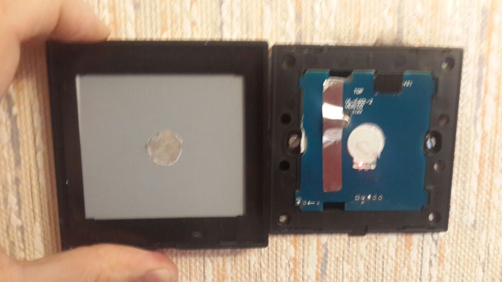
On mine, the brain mcu is on the capacitive plate (a microchip mcu). I have not tried to access/change fw of the mcu though but I thought, well, I could do another plate and reuse relay board, easy!..but then there is the radio. Reuse the livolo one? some work, not the best perf, no state back.. Use my rfm69 radio (I prefer 868 than 433) ? I'm not sure the livolo can provide power I need etc... so it could put me on a tricky road for not great results, looking not good inside the box..
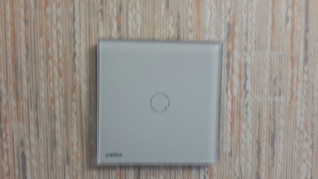
Too bad! Because my livolo is well built and I like the glass plate. I want the glass plate!! It's cheap and you have the whole enclosure.
So finally, I have a project in progress where I do everything from scratch, with glass plate and gesture, yep ;) but I don't know yet when it will be finished as I have a few other things to finish.@scalz said:
On mine, the brain mcu is on the capacitive plate (a microchip mcu). I have not tried to access/change fw of the mcu though but I thought, well, I could do another plate and reuse relay board, easy!..but then there is the radio. Reuse the livolo one? some work, not the best perf, no state back.. Use my rfm69 radio (I prefer 868 than 433) ? I'm not sure the livolo can provide power I need etc... so it could put me on a tricky road for not great results, looking not good inside the box..
Hello, I have ordered one full livolo switch, single button with no radio.
And I think I will disagree with you on this :)I've soldered some pins on the available headers (next to the 2*7 connector) and plugged a sensor on the GND and 3V pins.
The switch is still running fine, led on and I can switch the lights on and off. The sensor is running and sending data very reliably at the moment meaning even on the non-radio version of the switch the power is clean enough for NRF24 radio. This is true for both lights on and off.It might not be true when using the 4 switches version with all relays on, but this is making me very confident about the 2/3 switches version which would fill my needs.
I'm using US sized switches also, so maybe (probably) the power supply is not the same on the EU sized switches that has a maximum of 2 relays.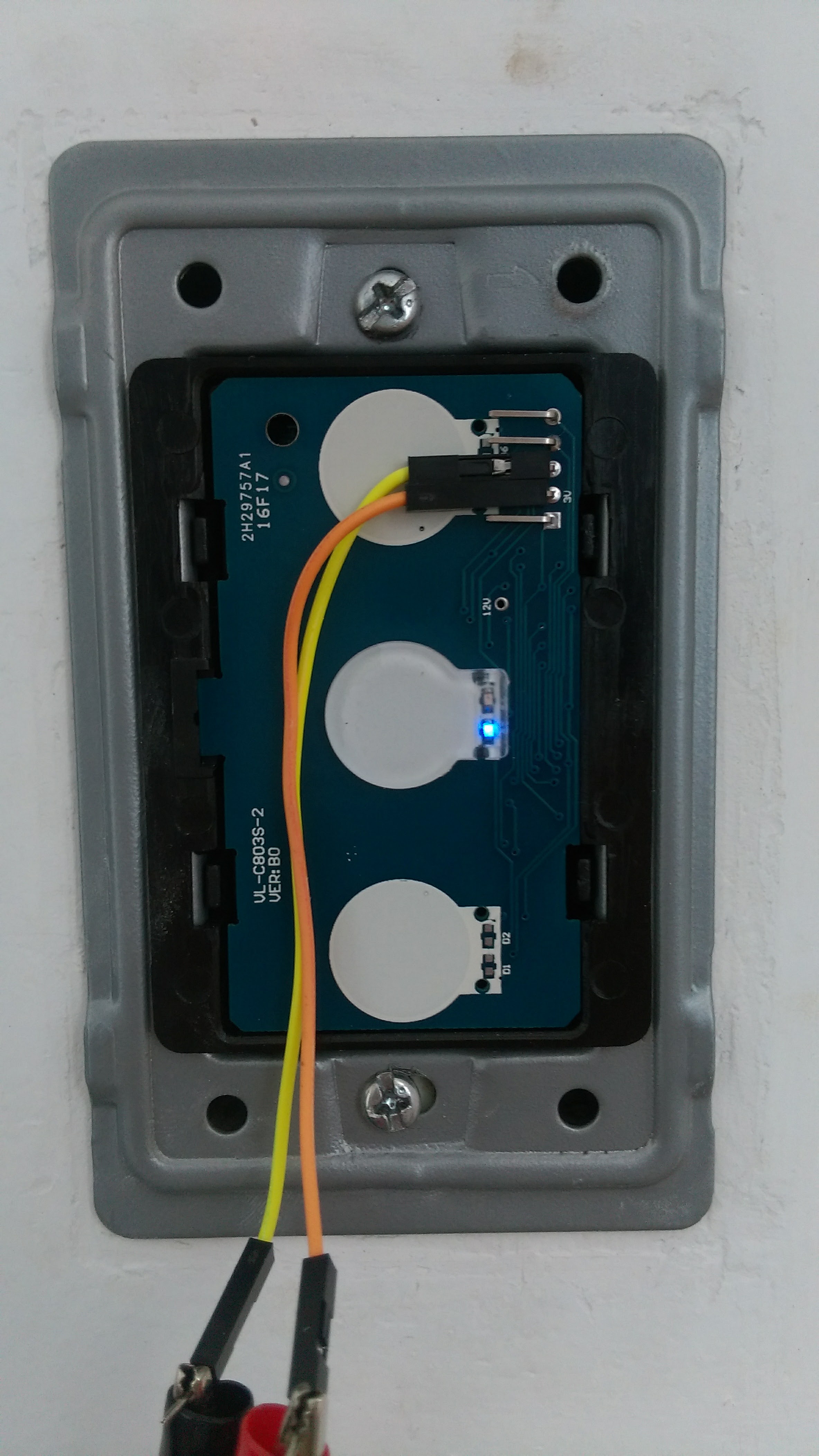
-
this guy did some work on this:
https://www.youtube.com/watch?v=ykqv4bZ9zb0 -
this guy did some work on this:
https://www.youtube.com/watch?v=ykqv4bZ9zb0@Cristian-Tone said:
this guy did some work on this:
https://www.youtube.com/watch?v=ykqv4bZ9zb0Yes I have seen it but it's a completely different concept. They reprogram the PIC on the sensor board so it will send data to a computer over serial. And last time I saw it they had to change the relays also to put 5V relays instead of 12V.
It's much cleaner to just replace the sensor board and communicate through radio... -
@Cristian-Tone said:
this guy did some work on this:
https://www.youtube.com/watch?v=ykqv4bZ9zb0Yes I have seen it but it's a completely different concept. They reprogram the PIC on the sensor board so it will send data to a computer over serial. And last time I saw it they had to change the relays also to put 5V relays instead of 12V.
It's much cleaner to just replace the sensor board and communicate through radio...@Nca78 Indeed, I've done some more research on this too and I agree with you, it would have been nice though. :)
-
к сожалению не говорю по английски, вот код для ясности :smiley:
#include <SPI.h> #include <MySensor.h> #include <Bounce2.h> #define sensor_PIN 6 #define RELAY_PIN A3 // Arduino Digital I/O pin number for relay #define BUTTON_PIN 5 // Arduino Digital I/O pin number for button #define CHILD_ID 1 // Id of the sensor child #define RELAY_ON 1 #define RELAY_OFF 0 Bounce debouncer = Bounce(); int oldValue=0; bool state; bool sens; MySensor gw; MyMessage msg(CHILD_ID,V_LIGHT); void setup() { delay(2400); gw.begin(incomingMessage, AUTO, true); // Send the sketch version information to the gateway and Controller // gw.sendSketchInfo("Livolo", "1.0"); // Setup the button pinMode(BUTTON_PIN,INPUT); pinMode(sensor_PIN,INPUT); // Activate internal pull-up digitalWrite(BUTTON_PIN,HIGH); // After setting up the button, setup debouncer debouncer.attach(BUTTON_PIN); debouncer.interval(5); // Register all sensors to gw (they will be created as child devices) gw.present(CHILD_ID, S_LIGHT); delay(1400); // Make sure relays are off when starting up digitalWrite(RELAY_PIN, RELAY_OFF); // Then set relay pins in output mode pinMode(RELAY_PIN, OUTPUT); // Set relay to last known state (using eeprom storage) // state = gw.loadState(CHILD_ID); //digitalWrite(RELAY_PIN, state?RELAY_ON:RELAY_OFF); state=false; } /* * Example on how to asynchronously check for new messages from gw */ void loop() { gw.process(); //debouncer.update(); // Get the update value int value =digitalRead(sensor_PIN); if (value==1){ state=true; }else{ state=false; } if (value != oldValue) { gw.send(msg.set(state), true); // Send new state and request ack back } oldValue = value; } void incomingMessage(const MyMessage &message) { if (message.type == V_LIGHT) { // Change relay state bool instate = message.getBool(); while(instate!=state){ digitalWrite(RELAY_PIN, RELAY_ON); delay(60); digitalWrite(RELAY_PIN, RELAY_OFF); delay(60); int value =digitalRead(sensor_PIN); if (value==1){ state=true; }else{ state=false; } } } } -
Sorry if this already has been covered in the thread but I can't find the info. When looking at ebay it looks like the connectors are L = in, L1, = out (for one way). But how are the radio/touch etc powered? is there also a battery inside or can you power the switch without neutral wire?
-
Sorry if this already has been covered in the thread but I can't find the info. When looking at ebay it looks like the connectors are L = in, L1, = out (for one way). But how are the radio/touch etc powered? is there also a battery inside or can you power the switch without neutral wire?
@Cliff-Karlsson it takes the voltage from live wire only. It generates a light voltage drop and from there gets enough power to run the circuit.
The downside is it constantly have to leak a bit of current through the live wire, so if you have a small light connected to it it might flicker. Livolo sells some small unit you can connect to your load and that will let the current pass and save your lights from premature death because of flickering. But it all depends on the light bulbs and also on the quality/efficiency of the switches. -
There really is an opportunity to draw enough power from livolo internal circuits for atmega328 and a radio. With the great help of @DJONvl I managed to power up an arduino with nrf24 radio directly from the switch.
But...
I have a two button switch, and i tried to adopt the above scetch for my purpose (and the development version of the library) but got stuck... Can anyone please have a glance at my scetch and push me towards the right way? :)/** * The MySensors Arduino library handles the wireless radio link and protocol * between your home built sensors/actuators and HA controller of choice. * The sensors forms a self healing radio network with optional repeaters. Each * repeater and gateway builds a routing tables in EEPROM which keeps track of the * network topology allowing messages to be routed to nodes. * * Created by Henrik Ekblad <henrik.ekblad@mysensors.org> * Copyright (C) 2013-2015 Sensnology AB * Full contributor list: https://github.com/mysensors/Arduino/graphs/contributors * * Documentation: http://www.mysensors.org * Support Forum: http://forum.mysensors.org * * This program is free software; you can redistribute it and/or * modify it under the terms of the GNU General Public License * version 2 as published by the Free Software Foundation. * ******************************* */ #define MY_RADIO_NRF24 #define MY_REPEATER_FEATURE #include <MySensors.h> #define sensor1_PIN 5 #define sensor2_PIN 6 #define RELAY1_PIN 3 // Arduino Digital I/O pin number for relay #define RELAY2_PIN 4 #define CHILD_ID_LIGHT1 1 // Id of the sensor child #define CHILD_ID_LIGHT2 2 #define RELAY_ON 1 #define RELAY_OFF 0 int oldValue1=0; bool state1; bool sens1; int oldValue2=0; bool state2; bool sens2; //MySensor gw; MyMessage msg(CHILD_ID_LIGHT1,V_LIGHT); MyMessage msg2(CHILD_ID_LIGHT2,V_LIGHT); void setup() { delay(2400); pinMode(sensor1_PIN,INPUT); pinMode(sensor2_PIN,INPUT); digitalWrite(RELAY1_PIN, RELAY_OFF); // Make sure relays are off when starting up digitalWrite(RELAY2_PIN, RELAY_OFF); // Make sure relays are off when starting up pinMode(RELAY1_PIN, OUTPUT); // Then set relay pins in output mode pinMode(RELAY2_PIN, OUTPUT); // Then set relay pins in output mode state1=false; state2=false; } void presentation() { // Register all sensors to gw (they will be created as child devices) sendSketchInfo("Livolo", "1.2"); present(CHILD_ID_LIGHT1, S_LIGHT); present(CHILD_ID_LIGHT2, S_LIGHT); delay(1400); } void loop() { int value1 = digitalRead(sensor1_PIN); if (value1==1){ state1=true; }else{ state1=false; } if (value1 != oldValue1) { send(msg.set(state1), true); // Send new state and request ack back } oldValue1 = value1; int value2 = digitalRead(sensor2_PIN); if (value2==1){ state2=true; }else{ state2=false; } if (value2 != oldValue2) { send(msg2.set(state2), true); // Send new state and request ack back } oldValue2 = value2; } void receive(const MyMessage &message) { if (message.type == V_LIGHT) { // Change relay state bool instate = message.getBool(); while(instate!=state1){ digitalWrite(message.sensor, RELAY_ON); delay(30); digitalWrite(message.sensor, RELAY_OFF); delay(30); int value1 =digitalRead(sensor1_PIN); if (value1==1){ state1=true; }else{ state1=false; } int value2 =digitalRead(sensor2_PIN); if (value2==1){ state2=true; }else{ state2=false; } } } }The problem is in the receive()
I need to destinguish the incoming state for each sensor child and set the instate value accordigly.Please, help, I didn't sleep for so long :)
-
Well, somehow I got over it :)
Here is a working sketch for livolo two button switch:
/** * The MySensors Arduino library handles the wireless radio link and protocol * between your home built sensors/actuators and HA controller of choice. * The sensors forms a self healing radio network with optional repeaters. Each * repeater and gateway builds a routing tables in EEPROM which keeps track of the * network topology allowing messages to be routed to nodes. * * Created by Henrik Ekblad <henrik.ekblad@mysensors.org> * Copyright (C) 2013-2015 Sensnology AB * Full contributor list: https://github.com/mysensors/Arduino/graphs/contributors * * Documentation: http://www.mysensors.org * Support Forum: http://forum.mysensors.org * * This program is free software; you can redistribute it and/or * modify it under the terms of the GNU General Public License * version 2 as published by the Free Software Foundation. * ******************************* */ #define MY_RADIO_NRF24 #define MY_REPEATER_FEATURE #include <MySensors.h> #define sensor1_PIN 5 //Pin to attach the indicator LED1 #define sensor2_PIN 6 // LED2 #define RELAY1_PIN 3 // Arduino Digital I/O pin number for relay #define RELAY2_PIN 4 #define CHILD_ID_LIGHT1 1 // Id of the sensor child #define CHILD_ID_LIGHT2 2 #define RELAY_ON 1 #define RELAY_OFF 0 int oldValue1=0; bool state1; int oldValue2=0; bool state2; MyMessage msg(CHILD_ID_LIGHT1,V_LIGHT); MyMessage msg2(CHILD_ID_LIGHT2,V_LIGHT); void setup() { delay(2400); pinMode(sensor1_PIN,INPUT); pinMode(sensor2_PIN,INPUT); digitalWrite(RELAY1_PIN, RELAY_OFF); // Make sure relays are off when starting up digitalWrite(RELAY2_PIN, RELAY_OFF); // Make sure relays are off when starting up pinMode(RELAY1_PIN, OUTPUT); // Then set relay pins in output mode pinMode(RELAY2_PIN, OUTPUT); // Then set relay pins in output mode state1=false; state2=false; } void presentation() { // Register all sensors to gw (they will be created as child devices) sendSketchInfo("Livolo", "2.0"); present(CHILD_ID_LIGHT1, S_LIGHT); present(CHILD_ID_LIGHT2, S_LIGHT); delay(1400); } void loop() { int value1 = digitalRead(sensor1_PIN); if (value1==1){ state1=true; }else{ state1=false; } if (value1 != oldValue1) { send(msg.set(state1), true); // Send new state and request ack back } oldValue1 = value1; int value2 = digitalRead(sensor2_PIN); if (value2==1){ state2=true; }else{ state2=false; } if (value2 != oldValue2) { send(msg2.set(state2), true); // Send new state and request ack back } oldValue2 = value2; } void receive(const MyMessage &message) { if (message.type == V_LIGHT) { // Change relay state switch (message.sensor) { case 1: state1=message.getBool(); digitalWrite(message.sensor+2, RELAY_ON); delay(30); digitalWrite(message.sensor+2, RELAY_OFF); delay(30); break; case 2: state2 = message.getBool(); digitalWrite(message.sensor+2, RELAY_ON); delay(30); digitalWrite(message.sensor+2, RELAY_OFF); delay(30); break; } } } -
Well, somehow I got over it :)
Here is a working sketch for livolo two button switch:
/** * The MySensors Arduino library handles the wireless radio link and protocol * between your home built sensors/actuators and HA controller of choice. * The sensors forms a self healing radio network with optional repeaters. Each * repeater and gateway builds a routing tables in EEPROM which keeps track of the * network topology allowing messages to be routed to nodes. * * Created by Henrik Ekblad <henrik.ekblad@mysensors.org> * Copyright (C) 2013-2015 Sensnology AB * Full contributor list: https://github.com/mysensors/Arduino/graphs/contributors * * Documentation: http://www.mysensors.org * Support Forum: http://forum.mysensors.org * * This program is free software; you can redistribute it and/or * modify it under the terms of the GNU General Public License * version 2 as published by the Free Software Foundation. * ******************************* */ #define MY_RADIO_NRF24 #define MY_REPEATER_FEATURE #include <MySensors.h> #define sensor1_PIN 5 //Pin to attach the indicator LED1 #define sensor2_PIN 6 // LED2 #define RELAY1_PIN 3 // Arduino Digital I/O pin number for relay #define RELAY2_PIN 4 #define CHILD_ID_LIGHT1 1 // Id of the sensor child #define CHILD_ID_LIGHT2 2 #define RELAY_ON 1 #define RELAY_OFF 0 int oldValue1=0; bool state1; int oldValue2=0; bool state2; MyMessage msg(CHILD_ID_LIGHT1,V_LIGHT); MyMessage msg2(CHILD_ID_LIGHT2,V_LIGHT); void setup() { delay(2400); pinMode(sensor1_PIN,INPUT); pinMode(sensor2_PIN,INPUT); digitalWrite(RELAY1_PIN, RELAY_OFF); // Make sure relays are off when starting up digitalWrite(RELAY2_PIN, RELAY_OFF); // Make sure relays are off when starting up pinMode(RELAY1_PIN, OUTPUT); // Then set relay pins in output mode pinMode(RELAY2_PIN, OUTPUT); // Then set relay pins in output mode state1=false; state2=false; } void presentation() { // Register all sensors to gw (they will be created as child devices) sendSketchInfo("Livolo", "2.0"); present(CHILD_ID_LIGHT1, S_LIGHT); present(CHILD_ID_LIGHT2, S_LIGHT); delay(1400); } void loop() { int value1 = digitalRead(sensor1_PIN); if (value1==1){ state1=true; }else{ state1=false; } if (value1 != oldValue1) { send(msg.set(state1), true); // Send new state and request ack back } oldValue1 = value1; int value2 = digitalRead(sensor2_PIN); if (value2==1){ state2=true; }else{ state2=false; } if (value2 != oldValue2) { send(msg2.set(state2), true); // Send new state and request ack back } oldValue2 = value2; } void receive(const MyMessage &message) { if (message.type == V_LIGHT) { // Change relay state switch (message.sensor) { case 1: state1=message.getBool(); digitalWrite(message.sensor+2, RELAY_ON); delay(30); digitalWrite(message.sensor+2, RELAY_OFF); delay(30); break; case 2: state2 = message.getBool(); digitalWrite(message.sensor+2, RELAY_ON); delay(30); digitalWrite(message.sensor+2, RELAY_OFF); delay(30); break; } } }@Tigroenot said:
Well, somehow I got over it :)
Here is a working sketch for livolo two button switch:
/**
 * The MySensors Arduino library handles the wireless radio link and protocol
 * between your home built sensors/actuators and HA controller of choice.
 * The sensors forms a self healing radio network with optional repeaters. Each
 * repeater and gateway builds a routing tables in EEPROM which keeps track of the
 * network topology allowing messages to be routed to nodes.
 *
 * Created by Henrik Ekblad <henrik.ekblad@mysensors.org>
 * Copyright (C) 2013-2015 Sensnology AB
 * Full contributor list: https://github.com/mysensors/Arduino/graphs/contributors
 *
 * Documentation: http://www.mysensors.org
 * Support Forum: http://forum.mysensors.org
 *
 * This program is free software; you can redistribute it and/or
 * modify it under the terms of the GNU General Public License
 * version 2 as published by the Free Software Foundation.
 *
 *******************************
*/


#define MY_RADIO_NRF24
#define MY_REPEATER_FEATURE
#include <MySensors.h>

#define sensor1_PIN 5  //Pin to attach the indicator LED1
#define sensor2_PIN 6   // LED2
#define RELAY1_PIN 3  // Arduino Digital I/O pin number for relay
#define RELAY2_PIN 4
#define CHILD_ID_LIGHT1 1   // Id of the sensor child
#define CHILD_ID_LIGHT2 2
#define RELAY_ON 1
#define RELAY_OFF 0

int oldValue1=0;
bool state1;
int oldValue2=0;
bool state2;

MyMessage msg(CHILD_ID_LIGHT1,V_LIGHT);
MyMessage msg2(CHILD_ID_LIGHT2,V_LIGHT);

void setup()
{
  delay(2400);
   pinMode(sensor1_PIN,INPUT);
   pinMode(sensor2_PIN,INPUT);
   digitalWrite(RELAY1_PIN, RELAY_OFF); // Make sure relays are off when starting up
   digitalWrite(RELAY2_PIN, RELAY_OFF); // Make sure relays are off when starting up
   pinMode(RELAY1_PIN, OUTPUT);         // Then set relay pins in output mode
   pinMode(RELAY2_PIN, OUTPUT);         // Then set relay pins in output mode
   state1=false;
state2=false;
}

void presentation()
{
  // Register all sensors to gw (they will be created as child devices)
  sendSketchInfo("Livolo", "2.0");
  present(CHILD_ID_LIGHT1, S_LIGHT);
  present(CHILD_ID_LIGHT2, S_LIGHT);
  delay(1400);
}

void loop()
{

 int value1 = digitalRead(sensor1_PIN);
    if (value1==1){
      state1=true;
    }else{
      state1=false;
    }

  if (value1 != oldValue1) {
      send(msg.set(state1), true); // Send new state and request ack back
  }
  oldValue1 = value1;

  int value2 = digitalRead(sensor2_PIN);
  if (value2==1){
      state2=true;
    }else{
      state2=false;
    }
  if (value2 != oldValue2) {
      send(msg2.set(state2), true); // Send new state and request ack back
  }
  oldValue2 = value2;
}

void receive(const MyMessage &message) {

  if (message.type == V_LIGHT) {
     // Change relay state
switch (message.sensor) {
      case 1:
        state1=message.getBool();
        digitalWrite(message.sensor+2, RELAY_ON);
        delay(30);
        digitalWrite(message.sensor+2, RELAY_OFF);
        delay(30);
        break;
      case 2:
        state2 = message.getBool();
        digitalWrite(message.sensor+2, RELAY_ON);
        delay(30);
        digitalWrite(message.sensor+2, RELAY_OFF);
        delay(30);
        break;
      }
   }
}
I am also playing around with the livolo dubble switch, but I am still figuring out how to control the switch via the header on the Switch board (thus without the base unit).
Can you share also your hardware setup, this will be very helpfull for me.
Thanks in advance. -
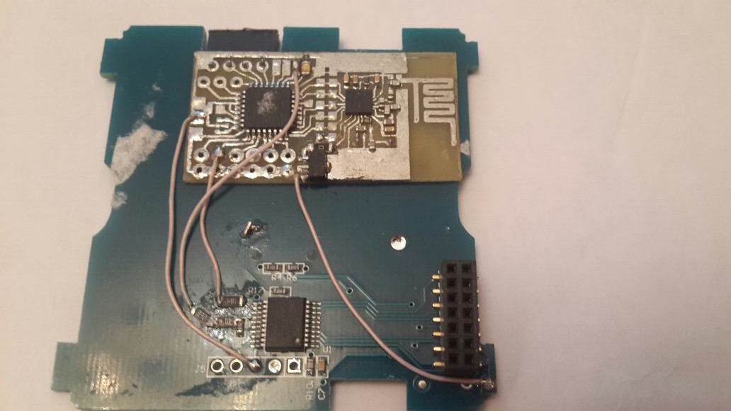
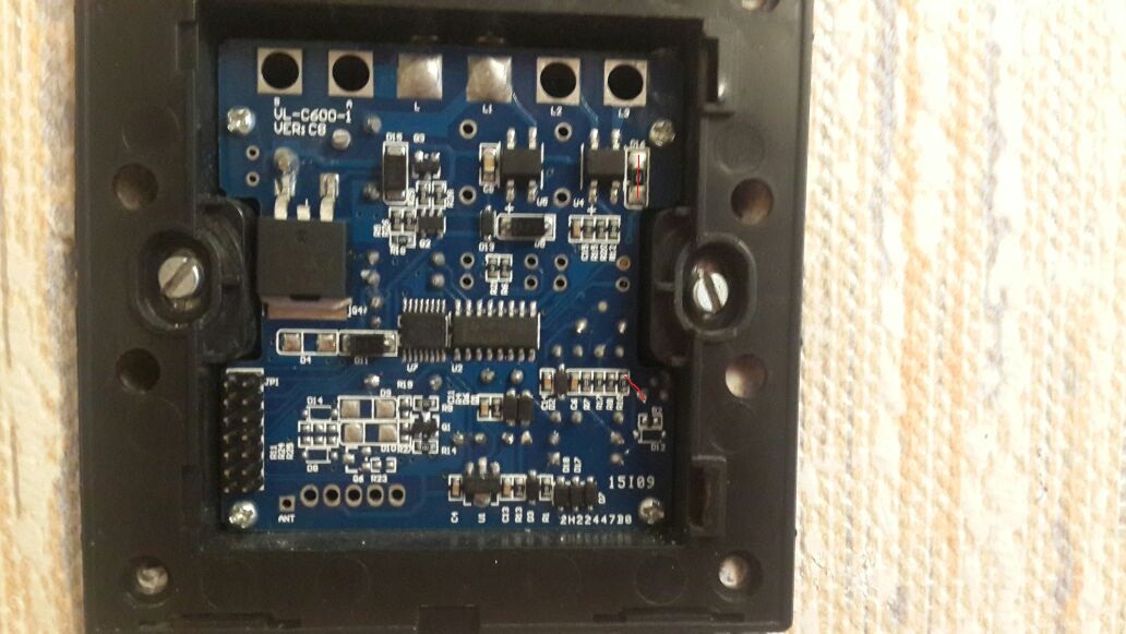
Hello, for those who have it, can you please confirm if it contains a CD74HC238 like I have in the US(AU) sized switch ? (same PCB for 1 and 3 switches). Chip marking on my chip is HJ238. It then feeds a darlington array chip (marking UN2003A on mine) to trigger the relays.
These would be the 2 ICs in the middle of the last picture from @DJONvl
Would be interesting to know as it would mean the touch PCB for both types of switches would be very similar. -
@Nca78 The euro version doesn't. Just the ULN2003A.
Unfortunately, I can't attach images for some unknown reason.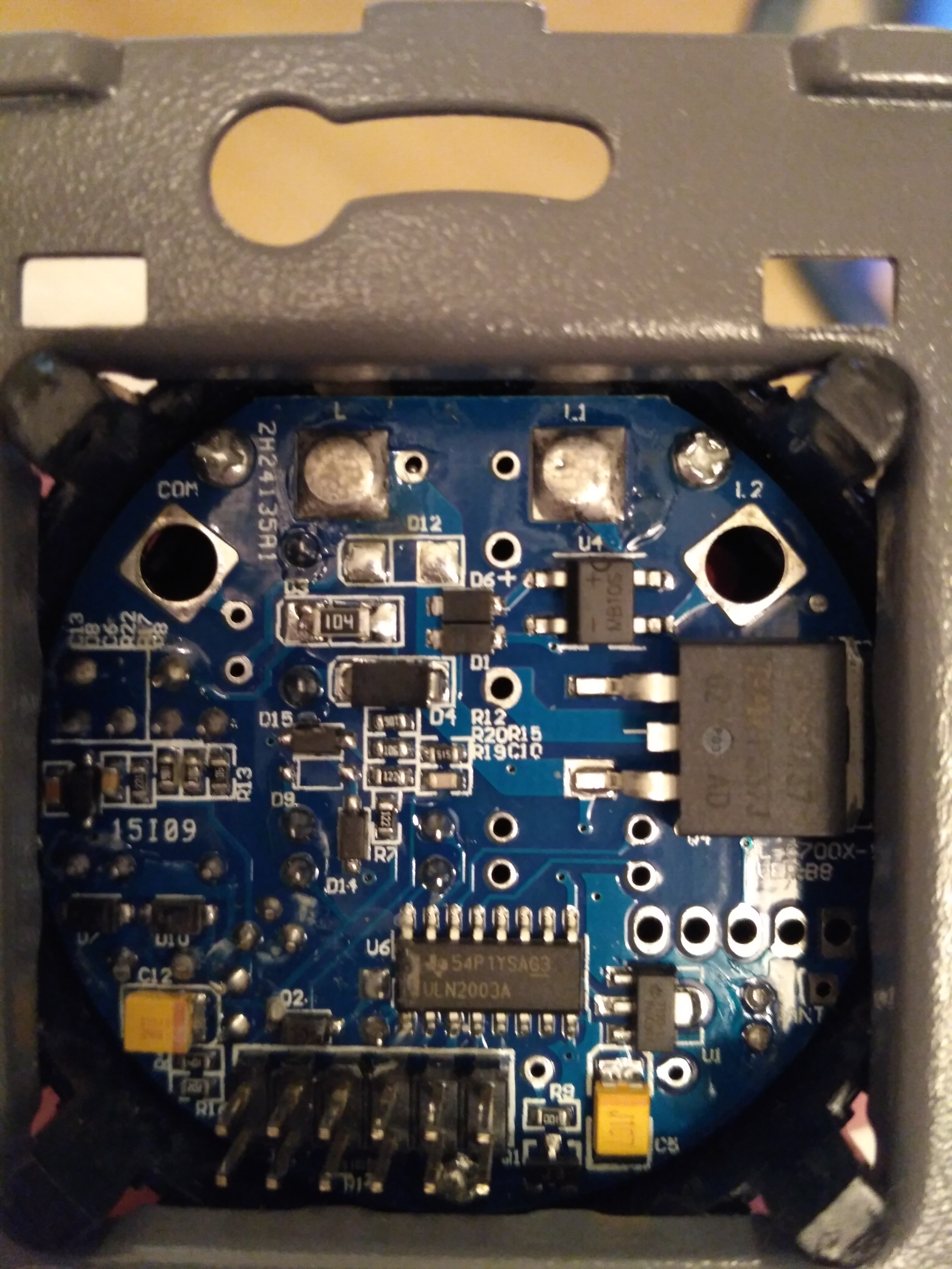
Finally :)
That's a single button switch.@Tigroenot this is a picture of the EU dubble switch version.
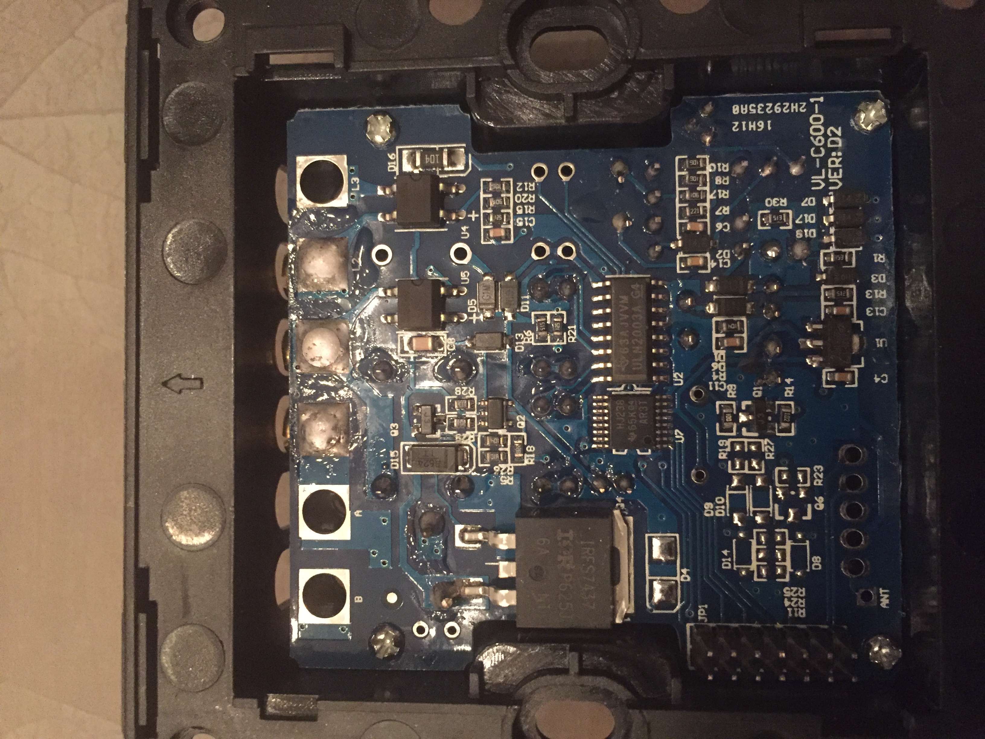 image url)
But what I am looking for is how to connect the arduino to this PCB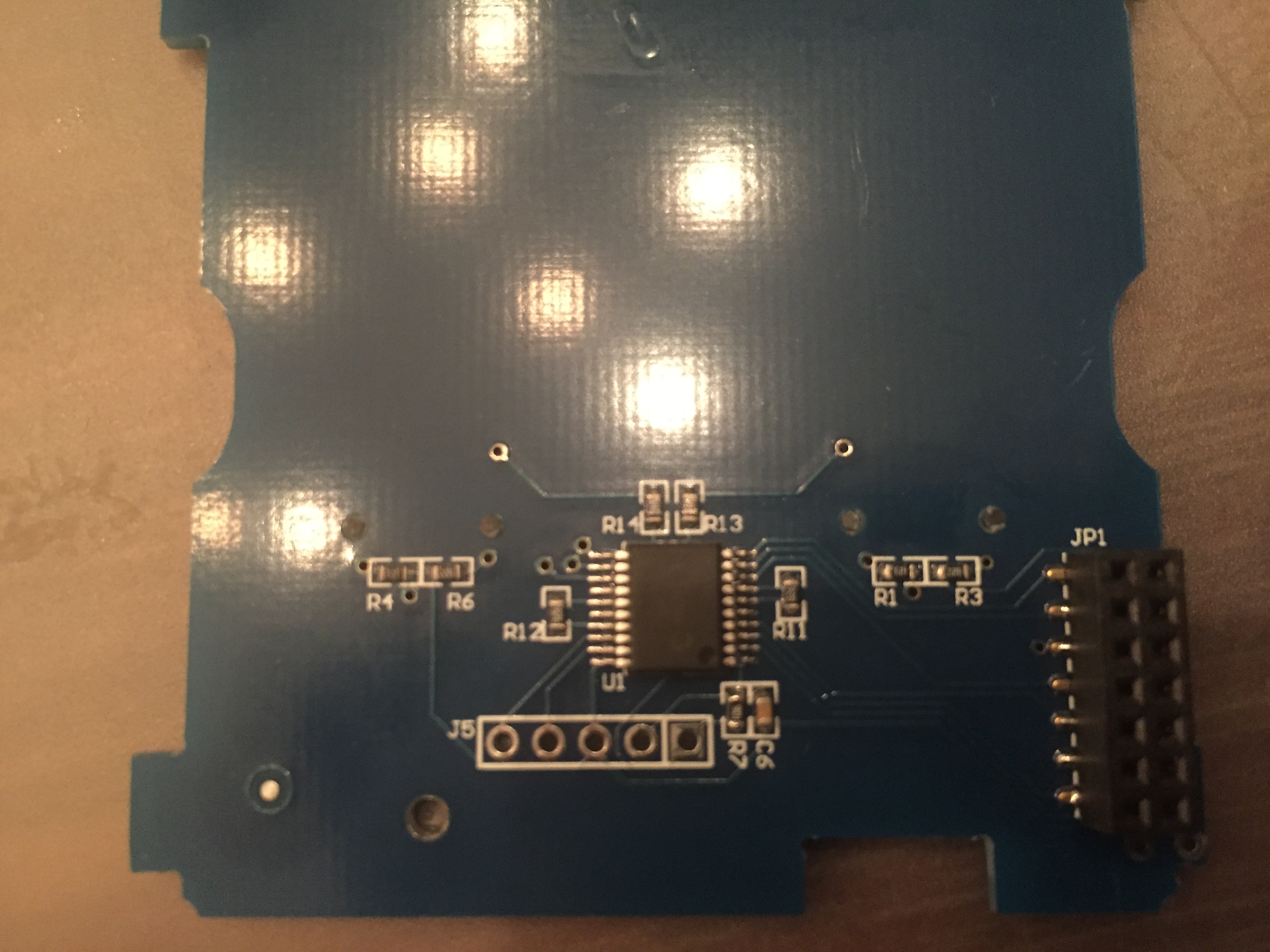
The picture of DJONvI is a good start, but I want to know if the SMD components which where added are resistors or a before I blow up the PCB ;-) -
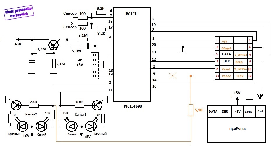
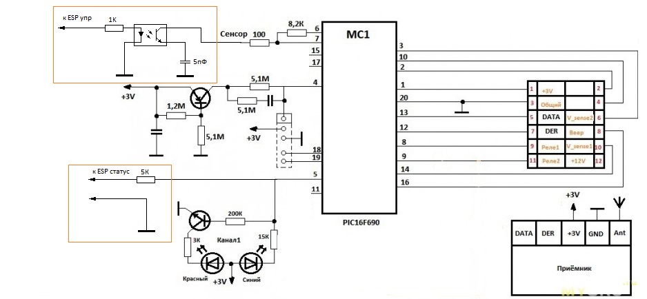
@frankie This diagram shows how a guy fixed his switch that didn't change the rele. But it is quite right. You need to add an optocoupler to connect to the sensor pin with 5,1 pF con to ground and connect the LED to the arduino sensor pin through resistor for the status read. I'll try to find the diagram later.
-
Thank you very much for the pictures @frankie and @Tigroenot !
No 74HC238 on the single switch which can be understood as it's not necessary, with one switch there are enough pins to drive the relay. But it's nicer in the US(AU) world as they are using the same PCB for both and just mounting one relay and one sensor.
On the Russian schematic it is not matching the board you have photographed @frankie as it has a 12 pins connector (2x6) instead of 14 (2x7) on yours (and mine, too). From what I see your board is very similar similar to mine with the 74HC238 and the pins are different than on the schematic. I'm a bit confused with this as this schematic seems to manage 2 buttons/relays.
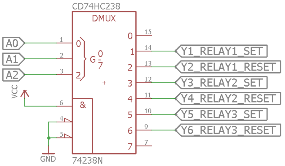
HC238 will decode value sent by 3 pins on the connector, and set HIGH one of it's 8 outputs based on the binary value. For example, if input is 000 then output 0 is high, if input is 010 then output 2 is high, etc. All other outputs of the 74HC238 are low.
This is done because they are using bistable relays. For each relay there is a SET latch to switch on, and RESET latch to switch off. When it's not switching, the relays stays in it's state without consuming any power. This is a smart way of doing the board to keep it low power, but you need 2 pins for each relay which the PIC controller on the sensor board doesn't have. As they use the 74HC238 they can command up to 4 relays.I used my multimeter and datasheets for the 2ICs to find out how they were connected and this is what I found out for my switch, US(AU) with 1 or 3 buttons/relays. I'm not saying you have the same mapping, you should check the datasheets to find out the input pins on the 74HC238 and verify with your multimeter to which pin of the connector they are connected.
Pinout (only for the pins I'm interested in...). Big squares at the top are the mains connectors.
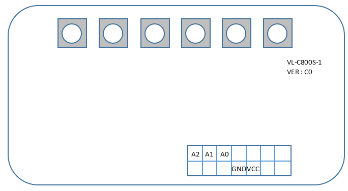
Pinout of the 74HC238 :
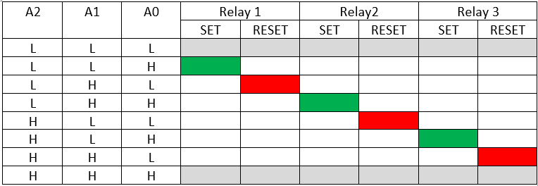
Values on the connector pins to switch on/off the relays:
Hello! It looks like you're interested in this conversation, but you don't have an account yet.
Getting fed up of having to scroll through the same posts each visit? When you register for an account, you'll always come back to exactly where you were before, and choose to be notified of new replies (either via email, or push notification). You'll also be able to save bookmarks and upvote posts to show your appreciation to other community members.
With your input, this post could be even better 💗
Register Login