Help needed - SSR switch / SCR dimmer
-
@stedew
Hi Stefan, and thanks.I agree that I might have to crawl before I run ;)
In the link you provided there are two 30k ½W resistors in front of the bridge rectifier. Would they not produce a lot of heat as well?
He uses a bridge rectifier. As far as I know the only function of that is to convert AC to DC, but it would still be 240V and be in a waveform.
The zero-point detector I ordered (based on the Arduino playground schematic) can handle a bi-directional input, as opposed to the 4n25 that is used on Instructables, so couldn't I just leave the rectifier out?@ksga
idd the bridge is not needed because the H1AA1 has two antiparrallel diodes.
As i said before the heat is a function I³*R. So yes, these resistors will get very hot (1W consumption @ 240V in total) It is ilmho not a good idea to use it like this given the fact that you get a few resistors in your circuit that always consume 1W even when the dimmer is off (and the resistors get very hot when you use a 1/2w type)
Yust imagine you consume 8760W every year yust to know the zero crossing.. -
@ksga
idd the bridge is not needed because the H1AA1 has two antiparrallel diodes.
As i said before the heat is a function I³*R. So yes, these resistors will get very hot (1W consumption @ 240V in total) It is ilmho not a good idea to use it like this given the fact that you get a few resistors in your circuit that always consume 1W even when the dimmer is off (and the resistors get very hot when you use a 1/2w type)
Yust imagine you consume 8760W every year yust to know the zero crossing..@stedew
But only if I have them before the ON/OFF relay ;)Okay... so when looking at the specs for the H11AA1 I can see that the maximum current on the input is 60mA.
Looking at lthis I've reached the conclusion - that I believe you wanted me to - that I have to lower the ac current before the zero-cross detector using an AC/AC transformer.
I'm having a bit of trouble finding a suitable (read - cheap) 240 / 6-0-6 AC/AC transformer. Any suggestions (prefer ebay or ali)?? -
@stedew
But only if I have them before the ON/OFF relay ;)Okay... so when looking at the specs for the H11AA1 I can see that the maximum current on the input is 60mA.
Looking at lthis I've reached the conclusion - that I believe you wanted me to - that I have to lower the ac current before the zero-cross detector using an AC/AC transformer.
I'm having a bit of trouble finding a suitable (read - cheap) 240 / 6-0-6 AC/AC transformer. Any suggestions (prefer ebay or ali)??@ksga
well i suggest you use google for this (the trafo). Also your link provide schema and code not so bad as a start. also there is a module (the Bluetooth classs) that set the power output from a literal in %. This is exactly what you need to bind it to Mysensor lib...
this is what i found on ebay Example link
This trafo does not provide much power but it is small and maybe sufficiënt for powering the arduino.
There is one catch when using a trafo : it introduce a phase shift so you must provide e methode (i believe a fix constant will do in most cases ) to trim the "offset" of the zero crossing.
As i am not a specialist on mysensors internal structure but for a atmega328p (uno) TCCR1A is used inseverall places ,for analog write Altsoftserial (RS485) etc. So you must be sure not to re-use the timer it will behave strange. Same is for the attachInterrupt function it is used in hwSleep function. As there are only 2 HW irq's you must choose the "right" one in most designs i believe irq 1 is used for the NRF24l01 /RFM69 so choose the other one on your mcu . For all these reasons i believe it will take many hours off testing to get the dimmer "glitch" free.
I believe for this resons it is better to offload the mcu and use a dedicated chip/mcu when you want to use Mysensors in your dimmer. -
Hi. Only my 5 cents...
Do not doubt. It is not possible to use the mysensors library (or another serious software) and to control a dimmer from one atmega328. Your controller will omit dimmer ISR during handling radio interrupts. I solved this problem using external attiny13 to control triac (it was a little challenge because attiny13 has only one timer and very little rom so I'd written program from scratch without arduino). It is not only one solution but it works and it is low cost. In this case we can use standard atmega328 as main controller (program it as standard arduino) and attiny13 as hardware controller. I have real prototype and may be I will route the board when will have time. -
Hi. Only my 5 cents...
Do not doubt. It is not possible to use the mysensors library (or another serious software) and to control a dimmer from one atmega328. Your controller will omit dimmer ISR during handling radio interrupts. I solved this problem using external attiny13 to control triac (it was a little challenge because attiny13 has only one timer and very little rom so I'd written program from scratch without arduino). It is not only one solution but it works and it is low cost. In this case we can use standard atmega328 as main controller (program it as standard arduino) and attiny13 as hardware controller. I have real prototype and may be I will route the board when will have time.@Koresh
Sounds like a good plan. Have you shared the code/design anywhere?@stedew
Thanks fo the link :)
Browsed Ali and ebay, but shipping is killing me on these trafos.
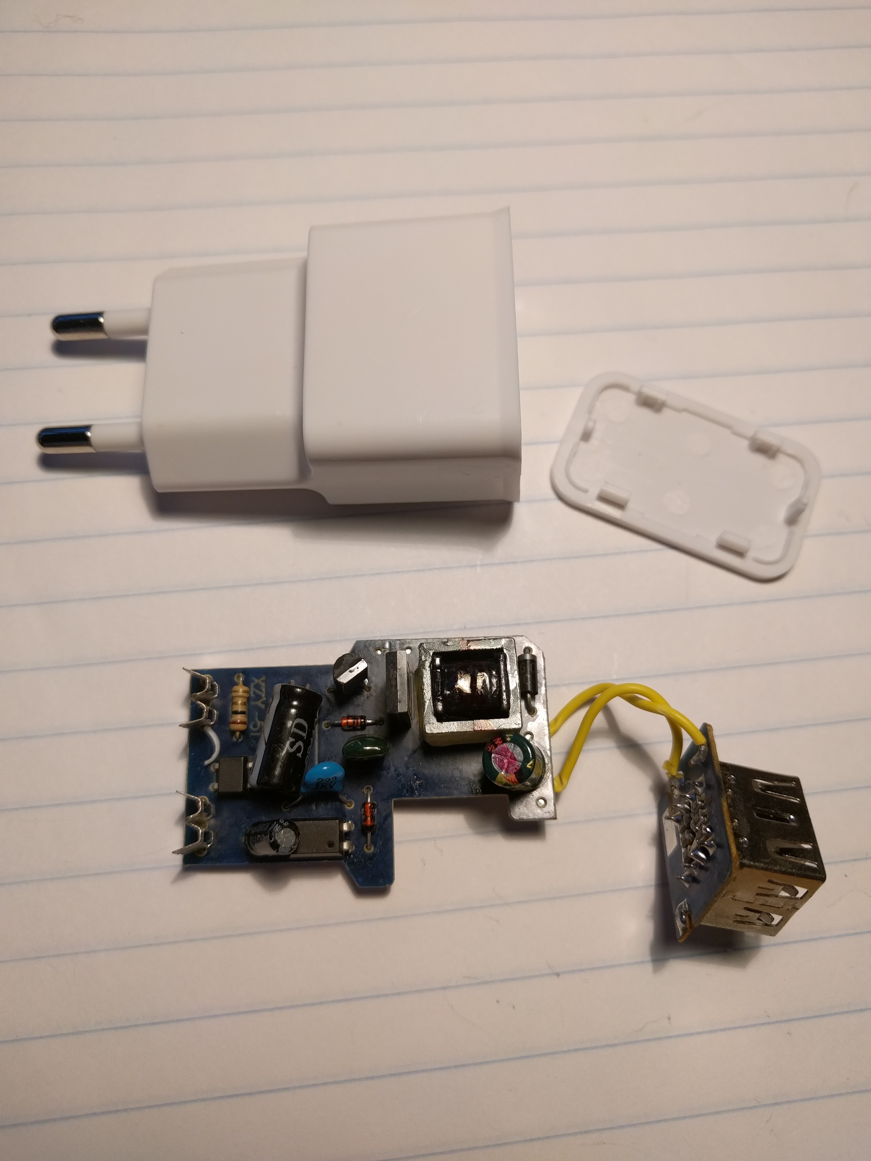
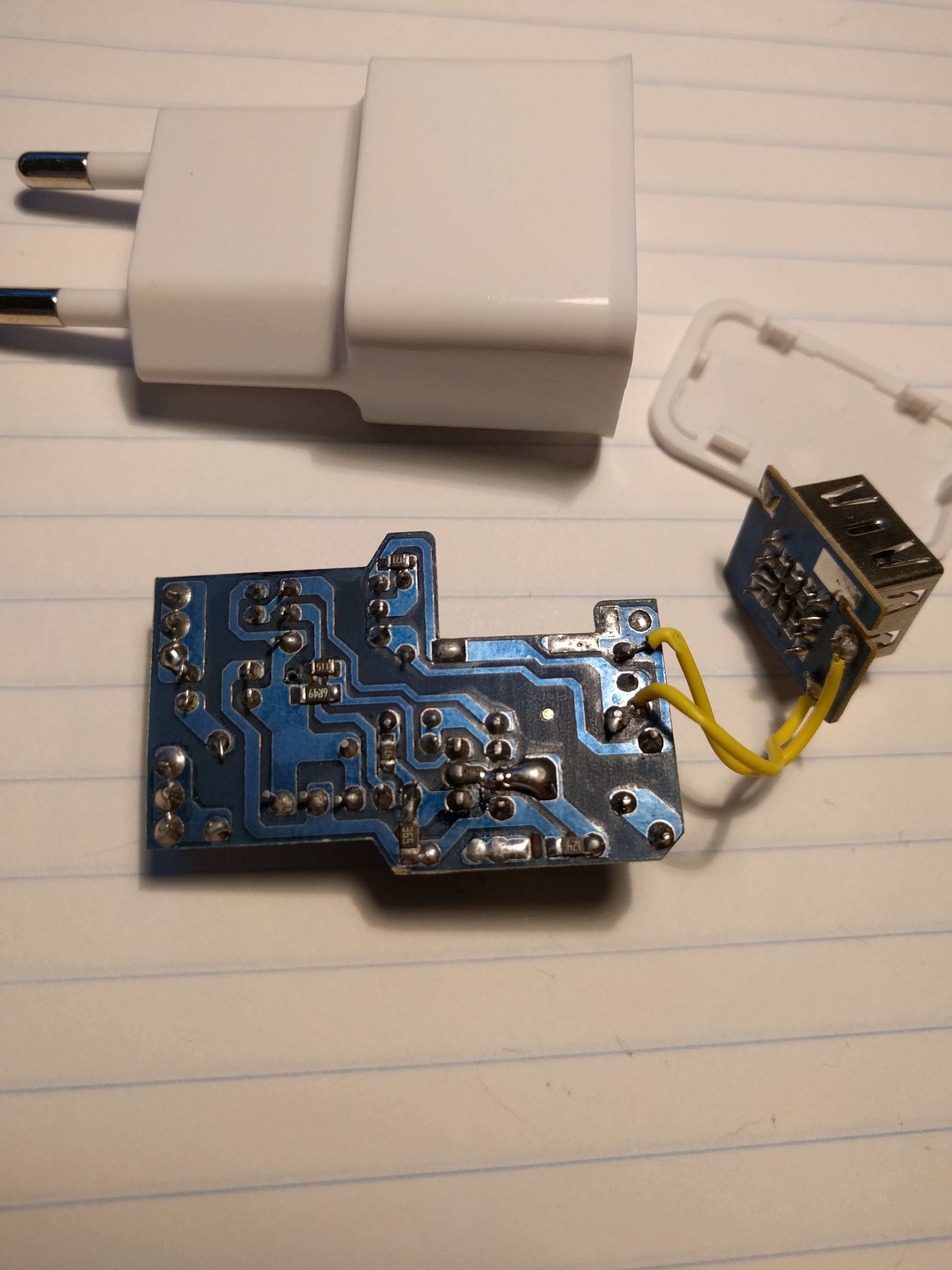
Got me wondering... a lot of cheap AC-DC transformers are flooding these sites in 5-12V variants.
Why not just take one of those apart - salvage the trafo and scrap the rest?I only need a few hundred mA to run arduino, radio and relay...
This is the kind of stuff I'm talking about (claims to be able to deliver 2A 5VDC - but that would only be if you had to start a fire...):
-
Hi. Only my 5 cents...
Do not doubt. It is not possible to use the mysensors library (or another serious software) and to control a dimmer from one atmega328. Your controller will omit dimmer ISR during handling radio interrupts. I solved this problem using external attiny13 to control triac (it was a little challenge because attiny13 has only one timer and very little rom so I'd written program from scratch without arduino). It is not only one solution but it works and it is low cost. In this case we can use standard atmega328 as main controller (program it as standard arduino) and attiny13 as hardware controller. I have real prototype and may be I will route the board when will have time. -
Isn't this something to get the same results: https://forum.mysensors.org/topic/5408/ultra-small-esp8266-node-with-2-channel-relay-temperature-dimmer-project
-
Isn't this something to get the same results: https://forum.mysensors.org/topic/5408/ultra-small-esp8266-node-with-2-channel-relay-temperature-dimmer-project
@FutureCow
Looks like it. But no code published...
Also - is the ESP8266 capable of handling the interrupts without messing up the timing when it is also responsible for communicating with the controller and the rest of the stuff?? -
-
@ksga said:
@Koresh
Cool.. could you share the code?New year holidays is the busy time :) I really want to start production of many boards within the coming weeks (my fulltime job projects and mysensors boards too). So I can't promise to share this project very soon (I am not sure you are interest in a code written in hurry and untested prototype). But I will try to do it asap :smirk:
Hello! It looks like you're interested in this conversation, but you don't have an account yet.
Getting fed up of having to scroll through the same posts each visit? When you register for an account, you'll always come back to exactly where you were before, and choose to be notified of new replies (either via email, or push notification). You'll also be able to save bookmarks and upvote posts to show your appreciation to other community members.
With your input, this post could be even better 💗
Register Login