RFM69 range issues
-
hmm, looks weird, what is your power supply? do you use dupont cable?
on my side, i already quickly tested 40m with one brickwall, outdoor rfm69cw (same as w) to my indoor rfm69hw GW, with mysensors 2 beta. -
@mihai.aldea
Could you please post your sketch?Have you set
#define MY_IS_RFM69HWaccording to your module type?
@FotoFieber said:
@mihai.aldea
Could you please post your sketch?Have you set
#define MY_IS_RFM69HWaccording to your module type?
No, I haven't. I just changed:
#define MY_RADIO_NRF24
//#define MY_RADIO_RFM69
to
//#define MY_RADIO_NRF24
#define MY_RADIO_RFM69
At some point I did try with:
#define MY_IS_RFM69HWbut no change.
I used the standard sketch, only modifying those two rows.
-
Do you mix 433MHz and 868MHz modules?
Sensor and gateway need to have the same type of modul.@gloob said:
Do you mix 433MHz and 868MHz modules?
Sensor and gateway need to have the same type of modul.Of course I did not mix them, how dumb can I be? :laughing:
I just happened to have another set which luckily were on a different frequency, as well as being the normal power types (without the "H") to rule out a possible signal saturation. -
hmm, looks weird, what is your power supply? do you use dupont cable?
on my side, i already quickly tested 40m with one brickwall, outdoor rfm69cw (same as w) to my indoor rfm69hw GW, with mysensors 2 beta.@scalz said:
hmm, looks weird, what is your power supply? do you use dupont cable?
on my side, i already quickly tested 40m with one brickwall, outdoor rfm69cw (same as w) to my indoor rfm69hw GW, with mysensors 2 beta.Initially I powered them from the Arduino Pro Mini onboard 3.3V voltage regulator which is supposed to handle up to 200mA. I also added capacitors. Then moved the setup to a larger breaboard powered by one of those breadboard power supplies. I powered the radios directly from the breadboard's 3.3V power rail. Also added capacitors.
Please note that each test was performed identically on both sensor node and serial gateway.The modules are connected to the Arduinos using short dupont cables. It's easier to prototype them by cutting a dupont cable set in two, solder the strip cable ends to the radio boards and connect the dupont pins on the breadboard. One thing worth mentioning is that the 868MHz modules are facing the chip side upwards and the 433MHz down.
Maybe the only thing that's not done 100% by the book is that I chose to connect the radios ground using the farmost GND pin instead of the one opposite the ANT pin. After I soldered them I found some schematics showing a dipole antenna setup using that pin as counterpoise for the antenna. But I assume that all GND pins are connected to the ground plane, so it really doesn't matter.
-
I haven't heard of countefeit RFM69 modules, but anyway, here are the exact modules, purchased from this exact supplier:
http://www.tme.eu/en/details/rfm69hw-433s2/rf-communication-modules/hope-microelectronics/
http://www.tme.eu/en/details/rfm69w-868s2/rf-communication-modules/hope-microelectronics/ -
I do not know if this will help but you could add the following to your sketch to make sure the radios are using the correct frequenzy:
#define MY_RFM69_FREQUENCY RF69_433MHZI think the default value if not defined is "RF69_868MHZ"
-
I do not know if this will help but you could add the following to your sketch to make sure the radios are using the correct frequenzy:
#define MY_RFM69_FREQUENCY RF69_433MHZI think the default value if not defined is "RF69_868MHZ"
@korttoma: Instead of inserting the #define in the sketch I modified the same entry in MyConfig.h. That's basically the same thing.
Anyway I must confess that at start, it took me some time to realize that :smile: That's because there's very little info on the RFM69 setups, almost all documentation revolves around RF24 and ESP8266 and the library and examples are pre-configured for RF24 :pensive: -
@korttoma: Instead of inserting the #define in the sketch I modified the same entry in MyConfig.h. That's basically the same thing.
Anyway I must confess that at start, it took me some time to realize that :smile: That's because there's very little info on the RFM69 setups, almost all documentation revolves around RF24 and ESP8266 and the library and examples are pre-configured for RF24 :pensive:These defines are mentioned here but some of then are missing the default value and a comment describing what they do.
-
side note: i've just update the docs for rfm69 ;)
about this issue, hmm..what if you directly connect a 82mm monopole wire directly on the radio ant pad? and powered from batt, like 2xAA/AAA.. looks weird!
-
side note: i've just update the docs for rfm69 ;)
about this issue, hmm..what if you directly connect a 82mm monopole wire directly on the radio ant pad? and powered from batt, like 2xAA/AAA.. looks weird!
@scalz Many thanks for updating the docs.
I was thinking about testing them with a battery as well but even if the remote sensors may be just fine with battery power, I still need the gateway radio to be fed with a constant 3.3V voltage from either the Arduino's 3.3V rail, or using a an external regulator. And so far neither worked.
I feel like there's something wrong with the radio modules. What ar the odds of those particular modules not to work with MySensors 2.0? -
side note: i've just update the docs for rfm69 ;)
about this issue, hmm..what if you directly connect a 82mm monopole wire directly on the radio ant pad? and powered from batt, like 2xAA/AAA.. looks weird!
@scalz said:
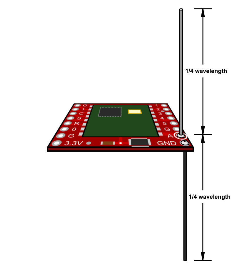
what if you directly connect a 82mm monopole wire directly on the radio ant pad?
I used a 17cm random wire for the 433MHz modules and 9cm wire for the 868MHz ones. Then coiled up the 17cm wires into a diy helical with 6-7 turns (not sure exctly)
-
for testing, perhaps better test with straight wire.
For 868Mhz, it's 82mm or it detune the radio. Also coil is nice for compact thing in box, but it decrease the range.
I hope you'll get it working, i've never got bad radio modules on my side, not yet!
With logs we could see if you get lot of fail, too, meaning bad range -
Some guides mention 87mm, others 82mm. As for the helical I will have to test and see. PCB antennas are also an option, but I'd hate to have my nice boxed sensors with wires hanging out.
As for the bad radio modules, that's one other reason I am focusing on the RFM69. I started experimenting with the cheap eBay NRF24L01+ modules, the black ones, only to later find out that about 1 out of 10 fails after sometime and doesn't enter the deep sleep mode, using about 2mA instead of about 60uA, obviously killing the battery after a day or so. I read about one guy who ordered 2000 or so and most of them had the exact same problem.
And since I am using rather expensive CR123 or 14250 batteries I don't want take that chance.
The green NRF24L01+ modules however, worked flawlessly so far but they're a bit too bulky for my projects. -
oki. i know for the 86mm, it also depends on the calc if i remember, that's why you can find both. but you said 9cm ;)
for your test, you should use straigth wire to be sure.
No stranded wire. Only one core inside.It's good to know, as rfm69 need an external ant, it requires more care for the anntenna sensitivity, for noise etc.. its emplacement, orientation, shape also matter etc.. so then it's sure it's compromise between acceptable range and compact devices.
Near a computer can also increase noise etc..
If everything is ok for ant, ok with defines in Mysensors, then it's probably on your HW. In this case, you may see some errors in your logs when you try. packet ack failed etc.. some logs ?? -
So... more tests performed:
I assumed that my moronic rush fried the modules power amps. I didn't carefully read the guide and hooked their I/O pins to a 5V Arduino pins (but connected the VCC pin to the 3.3V rail). So I pulled the last two factory sealed RFM69HW 433MHz I had stashed, soldered them with dupont cables and proper antenna (0.8mm copper single core 17cm long) and hooked one module to a 3.3V Arduino (the gateway to be) and the other one on a breadboard ATmega328 (the basic remote sensor architecture) powered by a 14250 battery.
The exact same thing :rage:
The LowPowerLab works for ranges up to 1m, the Radiohead library doesn't report anything on the serial interface and leds I used for basic debug shows that the sensor node sends packets but the gateway doesn't receive them.
So I got to a point where I'm very frustrated because there must be something I'm missing. I am using two module types at different frequency and power output, purchased from a trusted source, six months apart.
However, some further reading lead me to this page:
https://www.andrehessling.de/2015/02/07/figuring-out-the-power-level-settings-of-hoperfs-rfm69-hwhcw-modules/
This guy compiled a very thorough review of the modules in which he's playing with settings by enabling/disabling the radios power amps using writing registers. But I am totally clueless on how can this be done, if the MySensors has the proper settings preconfigured or if they're accessible and if so then where. It's not clear to me either if these registers are persistent across various sketches involving various libraries or if the used library has to have support for them and they need to be declared in every sketch or inside the library. This registry thing is pretty much where my expertise hits a wall :grin:
It's really strange that this 1m range is very consistend across a lot of setups I made. Maybe the power amps are disabled and they "hear" eachother while being very close, maybe by some sort of harmonics. -
So... more tests performed:
I assumed that my moronic rush fried the modules power amps. I didn't carefully read the guide and hooked their I/O pins to a 5V Arduino pins (but connected the VCC pin to the 3.3V rail). So I pulled the last two factory sealed RFM69HW 433MHz I had stashed, soldered them with dupont cables and proper antenna (0.8mm copper single core 17cm long) and hooked one module to a 3.3V Arduino (the gateway to be) and the other one on a breadboard ATmega328 (the basic remote sensor architecture) powered by a 14250 battery.
The exact same thing :rage:
The LowPowerLab works for ranges up to 1m, the Radiohead library doesn't report anything on the serial interface and leds I used for basic debug shows that the sensor node sends packets but the gateway doesn't receive them.
So I got to a point where I'm very frustrated because there must be something I'm missing. I am using two module types at different frequency and power output, purchased from a trusted source, six months apart.
However, some further reading lead me to this page:
https://www.andrehessling.de/2015/02/07/figuring-out-the-power-level-settings-of-hoperfs-rfm69-hwhcw-modules/
This guy compiled a very thorough review of the modules in which he's playing with settings by enabling/disabling the radios power amps using writing registers. But I am totally clueless on how can this be done, if the MySensors has the proper settings preconfigured or if they're accessible and if so then where. It's not clear to me either if these registers are persistent across various sketches involving various libraries or if the used library has to have support for them and they need to be declared in every sketch or inside the library. This registry thing is pretty much where my expertise hits a wall :grin:
It's really strange that this 1m range is very consistend across a lot of setups I made. Maybe the power amps are disabled and they "hear" eachother while being very close, maybe by some sort of harmonics.regarding the power level registers, they are set at full power when doing
#define MY_IS_RFM69HW
In the upcoming release, there will be autoadjustements of the power level.Like i said above, i'm running a local beta version with the new driver, but the one included actually gave me good results with rfm69hcw (same as HW) and my nodes are using rfm69cw (same as W).
Lowpowerlab lib works ok with mine. I'm not sure if i tried radiohead with them, but it was ok with rfm95..So that doesn't come from the lib. Unfortunately, it's consistent with your hardware&environment..that's not cool, i agree.
Also, i always noted that using wire between radio and breadboard, give more ack failed (using custom pcb, i don't notice this). because it can acts as sort of "ant" and add noise. But you should get more than 1m..What if you put them, says, 5meters apart, and plug power. Does it work?
So i would bet on lot of missed packets if you can't get more than 1m.- Do you have logs to see if you get some ack failed?
- Could you show a pic of your stuff, perhaps with two pair of eyes could help..
I'm missing ideas
-
Exactly, I've exhausted all my ideas as well. It must definitely be the hardware. As for your questions, I'm not sure they can even talk at a full 1m distance, more like 0.5m.
I have the custom PCB design ready for production but I don't want to submit it until I do some thorough testing. I looked for alternatives on the local market but I can only find breakout boards and besides their unfeasable cost, they're too bulky to fit inside my sensor cases.
I found that Anarduino sells custom modules with integrated RFM69(H)W (http://www.anarduino.com/miniwireless/) that look exactly like the one I have and the one depicted the guide here: https://www.mysensors.org/build/connect_radio
Adafruit's Feather, as well as the Sparkfun's breakout board are using a different looking module (the same found on eBay or Aliexpress)
Anarduino has an old RFM69 library but I'm struggling with Arduino IDE versions since the latest version throws a bunch of errors when compiling while 1.6.5 works just fine. But the funny thing is that even they recommend using the RadioHead library :laughing:Anyway, here's a bunch of pictures but I'm not sure if they're of any help.
http://imgur.com/a/yICkw -
I have had the same issues as you with the RFM69 modules.
First ones that I bought were marked as RFM69HCW 433mhz, and when I put them together as required, I couldn't get range of more than around 40cm. After that, the reception dropped off a cliff. One thing I did note was that the modules looked different from all the images I could see on this site, which led me to ponder whether I just had crummy modules or not. Also, given the size of the antenna, I was a bit loath to continue with 433mhz radios.
so I decided to up and pick up a new batch of radios, and change over to the RFM69HW (without the C), 868mhz. These ones, when I soldered them up, give me range of around 30m through the entire length of the house, through every wall.
So the only thing I could put my effort down to was that I just had a crummy radio module batch first, and a proper set later, so not sure I can put too much more knowledge into things here.
-
@Chester said:
I have had the same issues as you with the RFM69 modules.
First ones that I bought were marked as RFM69HCW 433mhz, and when I put them together as required, I couldn't get range of more than around 40cm. After that, the reception dropped off a cliff. One thing I did note was that the modules looked different from all the images I could see on this site, which led me to ponder whether I just had crummy modules or not. Also, given the size of the antenna, I was a bit loath to continue with 433mhz radios.
so I decided to up and pick up a new batch of radios, and change over to the RFM69HW (without the C), 868mhz. These ones, when I soldered them up, give me range of around 30m through the entire length of the house, through every wall.
So the only thing I could put my effort down to was that I just had a crummy radio module batch first, and a proper set later, so not sure I can put too much more knowledge into things here.
What you're saying makes perfect sense, crappy batches can hit the market sometimes. But what doesn't make any sense in my situation is that I first puchased 5x 868MHz RFM69W modules but as I had other ongoing projects they stayed on shelf for about half an year. Then I considered tinkering with 433MHz RFM69HW to test the longest possible range of RFM69x line.
Anyway, I absolutely need to use bare modules for my sensors so I will order a few from eBay and hopefully those ones will work.
Hello! It looks like you're interested in this conversation, but you don't have an account yet.
Getting fed up of having to scroll through the same posts each visit? When you register for an account, you'll always come back to exactly where you were before, and choose to be notified of new replies (either via email, or push notification). You'll also be able to save bookmarks and upvote posts to show your appreciation to other community members.
With your input, this post could be even better 💗
Register Login