Sending data from Arduino to Raspberry Pi via NRF24L01+
-
I am trying to send some ultrasonic data from an arduino uno to RPI3.
My Arduino Code is:// Enable debug prints to serial monitor #define MY_DEBUG // Enable and select radio type attached #define MY_RADIO_NRF24 // Set LOW transmit power level as default, if you have an amplified NRF-module and // power your radio separately with a good regulator you can turn up PA level. #define MY_RF24_PA_LEVEL RF24_PA_LOW // Enable serial gateway #define MY_GATEWAY_SERIAL // Define a lower baud rate for Arduino's running on 8 MHz (Arduino Pro Mini 3.3V & SenseBender) #if F_CPU == 8000000L #define MY_BAUD_RATE 38400 #endif // Enable inclusion mode #define MY_INCLUSION_MODE_FEATURE // Enable Inclusion mode button on gateway //#define MY_INCLUSION_BUTTON_FEATURE // Inverses behavior of inclusion button (if using external pullup) //#define MY_INCLUSION_BUTTON_EXTERNAL_PULLUP // Set inclusion mode duration (in seconds) #define MY_INCLUSION_MODE_DURATION 60 #define PARK_OFF_TIMEOUT 20000 // Number of milliseconds until turning off light when parked. #include <MySensors.h> #define SEND_STATUS_TO_CONTROLLER // Put a comment on this line for standalone mode //#include <NewPing.h> #ifdef SEND_STATUS_TO_CONTROLLER // Enable debug prints to serial monitor #define MY_DEBUG #include <SPI.h> #include <MySensors.h> #endif #ifdef SEND_STATUS_TO_CONTROLLER #define CHILD_ID 1 MyMessage msg(CHILD_ID,V_TRIPPED); #endif unsigned long sendInterval = 5000; // Send park status at maximum every 5 second. unsigned long lastSend; int oldParkedStatus=-1; #define echo_Pin 6 // Echo Pin #define trig_Pin 5 // Trigger Pin int blueledPin = 3; // the pin the LED is attached to (use one capable of PWM) int greenledPin = 7; int redledPin = 2; int a = 850; long duration, value; void setup() { // initialize serial communication: Serial.begin(115200); Serial.println("Starting distance sensor"); pinMode(greenledPin, OUTPUT); pinMode(redledPin, OUTPUT); } #ifdef SEND_STATUS_TO_CONTROLLER void presentation() { sendSketchInfo("Parking Sensor", "1.0"); present(CHILD_ID, S_DOOR, "Parking Status"); } #endif void loop() { //and the distance result in centimeters: pinMode(trig_Pin, OUTPUT); digitalWrite(trig_Pin, LOW); // Give a short LOW pulse beforehand to ensure a clean HIGH pulse: delayMicroseconds(10); digitalWrite(trig_Pin, HIGH); // The sensor is triggered by a HIGH pulse of 10 or more microseconds. delayMicroseconds(5); digitalWrite(trig_Pin, LOW); // Read the signal from the sensor: a HIGH pulse whose duration is the time (in microseconds) // from the sending of the ping to the reception of its echo off of an object. pinMode(echo_Pin, INPUT); duration = pulseIn(echo_Pin, HIGH); // value = microsecondsToCentimeters(duration); // convert the time into a distance value = (duration/58.138); Serial.print(value); Serial.print ("cm"); Serial.println(); // Displays readings one beneath other. delay(500); // Rate of displaying the readings // Update parked status int parked = value != 0 && value < 54; { if (parked) { Serial.println("Car Parked"); digitalWrite (redledPin, HIGH); delay(a); digitalWrite (redledPin, LOW); } else { Serial.println("Car Gone"); digitalWrite(greenledPin, HIGH); delay(a); digitalWrite(greenledPin, LOW); } } #ifdef SEND_STATUS_TO_CONTROLLER send(msg.set(parked)); #endif oldParkedStatus = parked; //lastSend = now; }While this code runs succefully (I Hope)
I would like to send the collected data on to a wordpress site from the Raspberry Pi 3 (RP3 is hosting one already). I would prefer to send it to an OpenHab or a controller to implement some functions.
But the main issue I am facing is this error.
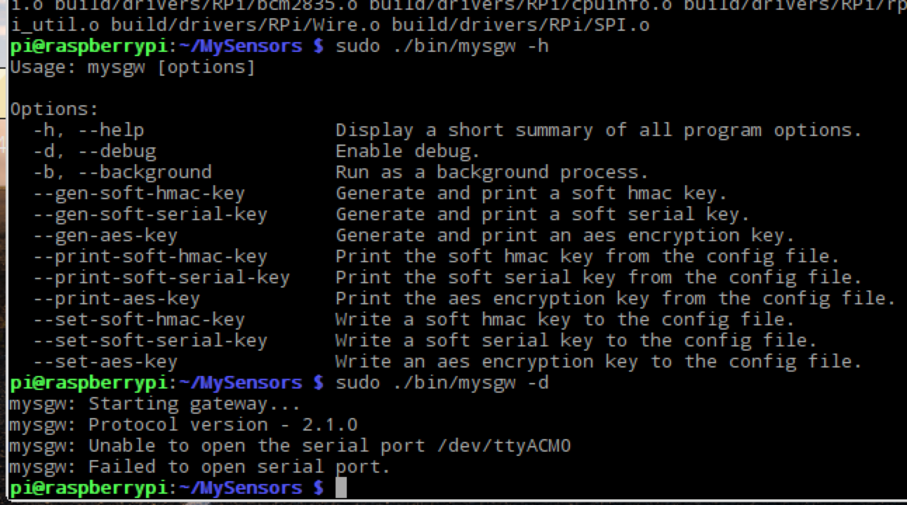
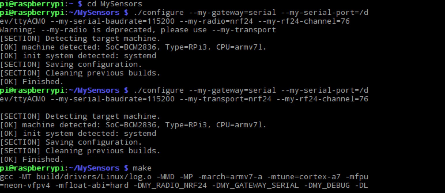
The configure used is
Some help would be appreciated.
-
Any solution?
-
@LaMB95 I am not sure I understand what you are trying to do but maybe you can use https://www.mysensors.org/build/raspberry on the rpi3 and remove the gateway part from your Uno.
-
Maybe you could take a look at this tutorial
https://forum.mysensors.org/topic/1151/tutorial-raspberry-pi-nrf24l01-direct-connection
-
@gohan better to use https://www.mysensors.org/build/raspberry which is compatible with MySensors 2.
What I am trying to do is to put the arduino in my garage and send this data to something like OpenHab or Wordpress such that I can see the parking status from another location.
And a couple of youtube tutorials I saw were able to send the data from an arduino to a pi (without any USB cable) using this radio.
I was hoping such a method is possible using the MySensors library.Another question I have is what aout using a virtual serial port ? But I think I would need an ethernet shield on the arduino. Am I right?
-
What I am trying to do is to put the arduino in my garage and send this data to something like OpenHab or Wordpress such that I can see the parking status from another location.
And a couple of youtube tutorials I saw were able to send the data from an arduino to a pi (without any USB cable) using this radio.
I was hoping such a method is possible using the MySensors library.Another question I have is what aout using a virtual serial port ? But I think I would need an ethernet shield on the arduino. Am I right?
@LaMB95 I don't know about virtual serial ports but sensing data from one Arduino to a gateway (which can be a raspberry pi) is exactly what MySensors is about.
https://www.mysensors.org/about describes how MySensors works. I suggest you start there, especially the part labelled "The sensor network"
In MySensors terminology, the arduino in the garage will be a sensor and the raspberry pi will be a gateway.
-
@LaMB95 I don't know about virtual serial ports but sensing data from one Arduino to a gateway (which can be a raspberry pi) is exactly what MySensors is about.
https://www.mysensors.org/about describes how MySensors works. I suggest you start there, especially the part labelled "The sensor network"
In MySensors terminology, the arduino in the garage will be a sensor and the raspberry pi will be a gateway.
I checked the page!
It was quite helpful and I realise that a serial gateway is not something that I need.I need some help to understand the working of a virtual serial port.
-
As a beginner as I am, I'd go with 2 Arduino boards and use one as gateway; it really simplify the initial setup even if you you actually have more hw. Meanwhile you could study how to use the nrf24 on the rpi3, that's more complicated and if you are not experienced it is easier to make mistakes
-
As a beginner as I am, I'd go with 2 Arduino boards and use one as gateway; it really simplify the initial setup even if you you actually have more hw. Meanwhile you could study how to use the nrf24 on the rpi3, that's more complicated and if you are not experienced it is easier to make mistakes
-
For the serial gateway just read https://www.mysensors.org/build/serial_gateway , it's quite straight forward as you just need to use the code in the example in the library and choose your customization options in the #DEFINE at the beginning of the code (DEBUG, type of radio, power level, if you want the 3 monitoring blinking leds); things get a little more complicated for the sensor nodes if you want to have more sensors attached to a single node, because you need to copy multiple code from examples and try to blend everything together; but if you start with a simple sensor node and tinker a little with it, then you can add more and more complexity looking for ideas around the forum or just google around.
To me the most difficult part has been getting the radio working because I bought some crappy modules that I had then replaced with working ones and that cost me a lot of time because I was afraid I was doing mistakes but I actually did everything correctly (as soon as I plugged in the new modules it started to work).
After I got communication established I just configured in domoticz a new hardware and I could choose either serial/Ethernet/mqtt mysensors gateway and that was it. As soon as you add new sensors that present themselves you can find them as "unused" sensors in the controller; after that it's all up to you. If you don't like the controller just install a new one and connect the gateway to it and you are ready to go. -
Here is the code of my ethernet gateway, so for serial just ignore all the part about network and w5100
// Enable debug prints to serial monitor
#define MY_DEBUG

// Enable and select radio type attached
#define MY_RADIO_NRF24
//#define MY_RADIO_RFM69

#define MY_RF24_PA_LEVEL RF24_PA_MAX

// Enable gateway ethernet module type
#define MY_GATEWAY_W5100

// W5100 Ethernet module SPI enable (optional if using a shield/module that manages SPI_EN signal)
//#define MY_W5100_SPI_EN 4

// Enable Soft SPI for NRF radio (note different radio wiring is required)
// The W5100 ethernet module seems to have a hard time co-operate with
// radio on the same spi bus.
#if !defined(MY_W5100_SPI_EN) && !defined(ARDUINO_ARCH_SAMD)
#define MY_SOFTSPI
#define MY_SOFT_SPI_SCK_PIN 14
#define MY_SOFT_SPI_MISO_PIN 16
#define MY_SOFT_SPI_MOSI_PIN 15
#endif

// When W5100 is connected we have to move CE/CSN pins for NRF radio
#ifndef MY_RF24_CE_PIN
#define MY_RF24_CE_PIN 5
#endif
#ifndef MY_RF24_CS_PIN
#define MY_RF24_CS_PIN 6
#endif

// Enable to UDP
//#define MY_USE_UDP

//#define MY_IP_ADDRESS 192,168,178,66   // If this is disabled, DHCP is used to retrieve address
// Renewal period if using DHCP
#define MY_IP_RENEWAL_INTERVAL 60000
// The port to keep open on node server mode / or port to contact in client mode
#define MY_PORT 5003

// Controller ip address. Enables client mode (default is "server" mode).
// Also enable this if MY_USE_UDP is used and you want sensor data sent somewhere.
//#define MY_CONTROLLER_IP_ADDRESS 192, 168, 178, 254

// The MAC address can be anything you want but should be unique on your network.
// Newer boards have a MAC address printed on the underside of the PCB, which you can (optionally) use.
// Note that most of the Ardunio examples use  "DEAD BEEF FEED" for the MAC address.
// #define MY_MAC_ADDRESS 0xDE, 0xAD, 0xBE, 0xEF, 0xFE, 0xED

// Enable inclusion mode
#define MY_INCLUSION_MODE_FEATURE
// Enable Inclusion mode button on gateway
//#define MY_INCLUSION_BUTTON_FEATURE
// Set inclusion mode duration (in seconds)
#define MY_INCLUSION_MODE_DURATION 60
// Digital pin used for inclusion mode button
//#define MY_INCLUSION_MODE_BUTTON_PIN  3

// Set blinking period
#define MY_DEFAULT_LED_BLINK_PERIOD 300

// Flash leds on rx/tx/err
// Uncomment to override default HW configurations
#define MY_DEFAULT_ERR_LED_PIN 1  // Error led pin
#define MY_DEFAULT_RX_LED_PIN  2  // Receive led pin
#define MY_DEFAULT_TX_LED_PIN  3  // Transmit led pin


#if defined(MY_USE_UDP)
#include <EthernetUdp.h>
#endif
#include <Ethernet.h>
#include <MySensors.h>


void setup()
{
}

void loop()
{
}
In MyConfig.h i changed these so it applies to all nodes/gateways
// Enables RF24 encryption (all nodes and gateway must have this enabled, and all must be personalized with the same AES key)
//#define MY_RF24_ENABLE_ENCRYPTION
#define MY_RF24_ENABLE_ENCRYPTION
#define MY_RF24_ENCRYPTKEY 0x15,0x12,0x11,0x08,0x01,0x07,0x01,0x03,0x016,0x14,0x15,0x05,0x03,0x09,0x16,0x07
#ifndef MY_RF24_CHANNEL #define MY_RF24_CHANNEL 1 #endif -
Here is the code of my ethernet gateway, so for serial just ignore all the part about network and w5100
// Enable debug prints to serial monitor
#define MY_DEBUG

// Enable and select radio type attached
#define MY_RADIO_NRF24
//#define MY_RADIO_RFM69

#define MY_RF24_PA_LEVEL RF24_PA_MAX

// Enable gateway ethernet module type
#define MY_GATEWAY_W5100

// W5100 Ethernet module SPI enable (optional if using a shield/module that manages SPI_EN signal)
//#define MY_W5100_SPI_EN 4

// Enable Soft SPI for NRF radio (note different radio wiring is required)
// The W5100 ethernet module seems to have a hard time co-operate with
// radio on the same spi bus.
#if !defined(MY_W5100_SPI_EN) && !defined(ARDUINO_ARCH_SAMD)
#define MY_SOFTSPI
#define MY_SOFT_SPI_SCK_PIN 14
#define MY_SOFT_SPI_MISO_PIN 16
#define MY_SOFT_SPI_MOSI_PIN 15
#endif

// When W5100 is connected we have to move CE/CSN pins for NRF radio
#ifndef MY_RF24_CE_PIN
#define MY_RF24_CE_PIN 5
#endif
#ifndef MY_RF24_CS_PIN
#define MY_RF24_CS_PIN 6
#endif

// Enable to UDP
//#define MY_USE_UDP

//#define MY_IP_ADDRESS 192,168,178,66   // If this is disabled, DHCP is used to retrieve address
// Renewal period if using DHCP
#define MY_IP_RENEWAL_INTERVAL 60000
// The port to keep open on node server mode / or port to contact in client mode
#define MY_PORT 5003

// Controller ip address. Enables client mode (default is "server" mode).
// Also enable this if MY_USE_UDP is used and you want sensor data sent somewhere.
//#define MY_CONTROLLER_IP_ADDRESS 192, 168, 178, 254

// The MAC address can be anything you want but should be unique on your network.
// Newer boards have a MAC address printed on the underside of the PCB, which you can (optionally) use.
// Note that most of the Ardunio examples use  "DEAD BEEF FEED" for the MAC address.
// #define MY_MAC_ADDRESS 0xDE, 0xAD, 0xBE, 0xEF, 0xFE, 0xED

// Enable inclusion mode
#define MY_INCLUSION_MODE_FEATURE
// Enable Inclusion mode button on gateway
//#define MY_INCLUSION_BUTTON_FEATURE
// Set inclusion mode duration (in seconds)
#define MY_INCLUSION_MODE_DURATION 60
// Digital pin used for inclusion mode button
//#define MY_INCLUSION_MODE_BUTTON_PIN  3

// Set blinking period
#define MY_DEFAULT_LED_BLINK_PERIOD 300

// Flash leds on rx/tx/err
// Uncomment to override default HW configurations
#define MY_DEFAULT_ERR_LED_PIN 1  // Error led pin
#define MY_DEFAULT_RX_LED_PIN  2  // Receive led pin
#define MY_DEFAULT_TX_LED_PIN  3  // Transmit led pin


#if defined(MY_USE_UDP)
#include <EthernetUdp.h>
#endif
#include <Ethernet.h>
#include <MySensors.h>


void setup()
{
}

void loop()
{
}
In MyConfig.h i changed these so it applies to all nodes/gateways
// Enables RF24 encryption (all nodes and gateway must have this enabled, and all must be personalized with the same AES key)
//#define MY_RF24_ENABLE_ENCRYPTION
#define MY_RF24_ENABLE_ENCRYPTION
#define MY_RF24_ENCRYPTKEY 0x15,0x12,0x11,0x08,0x01,0x07,0x01,0x03,0x016,0x14,0x15,0x05,0x03,0x09,0x16,0x07
#ifndef MY_RF24_CHANNEL #define MY_RF24_CHANNEL 1 #endif@gohan
Thanks for the code!I have been trying to send data from an Uno to a pro mini. Unfortunately, I have been receiving symbols and gibberish on the mini as it has be assigned as a receiver.
Any clue why?
I was hoping to send the collected data from the pro mini to the RPi3 via serial gateway and then to Domoticz.
Hello! It looks like you're interested in this conversation, but you don't have an account yet.
Getting fed up of having to scroll through the same posts each visit? When you register for an account, you'll always come back to exactly where you were before, and choose to be notified of new replies (either via email, or push notification). You'll also be able to save bookmarks and upvote posts to show your appreciation to other community members.
With your input, this post could be even better 💗
Register Login