💬 RFM69 Livolo 2 channels 1 way EU switch(VL-C700X-1 Ver: B8)
-
The thing is that I'm using the rfm69 radio module which draws a little bit more power than the nrf24l01 counterpart. It takes as much as 45-55mA(maybe 60mA at peak with all the rest including the microcontroller and the rest of components) and the avaialable regulator from the board supports 30mA (it's a 7130-1 device: http://www.bookly.com/images/BM71xx.pdf). Now it's true that the high power draw happens only on Tx(which doesn't take too much time usually - I think when using OTA it may be a little bit more intense) but I didn't wanted to risk.
-
@mtiutiu
Im really curious with this project and I go to order one Livolo switch now! :)
Count with me with one test pcb ;)I could use for example a more capable 3V regulator instead of the original one but again this is not ok as linear regulators are not very efficient when a big voltage drop is to be applied: 12V - 3V = 9V. This combined with a 60mA peak current leads to a 9V x 60mA = 540mW dissipated power on the linear voltage regulator which is a little bit too much as far as I know. Either way it requires hardware intervention so yeah...I don't think it matters too much. I didn't started with the nrf24l01 radio because I had a not so ok experience with it previously(packet loss and such) so I switched to the more capable rfm69 and it works flawlessly now(I have some other Mysensors nodes which I didn't published yet on openhardware.io but I will when I have time).
I'll do some more investigations regarding the power supply first and then I'll send the gerber files for production. I'll keep this thread updated.
-
@mtiutiu
Im really curious with this project and I go to order one Livolo switch now! :)
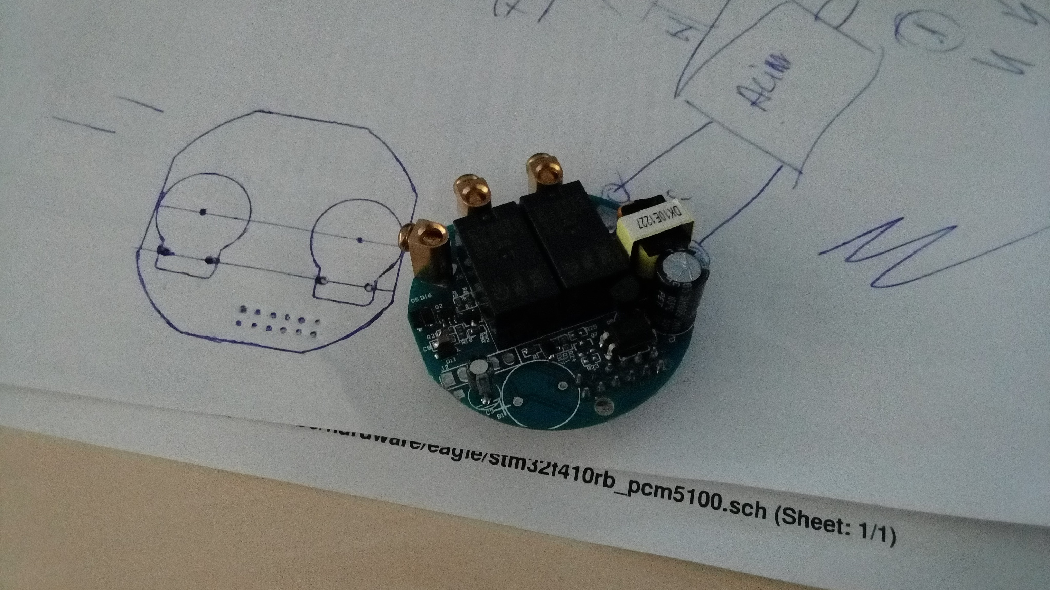
Count with me with one test pcb ;)The power/relays board looks like this:
-
I could use for example a more capable 3V regulator instead of the original one but again this is not ok as linear regulators are not very efficient when a big voltage drop is to be applied: 12V - 3V = 9V. This combined with a 60mA peak current leads to a 9V x 60mA = 540mW dissipated power on the linear voltage regulator which is a little bit too much as far as I know. Either way it requires hardware intervention so yeah...I don't think it matters too much. I didn't started with the nrf24l01 radio because I had a not so ok experience with it previously(packet loss and such) so I switched to the more capable rfm69 and it works flawlessly now(I have some other Mysensors nodes which I didn't published yet on openhardware.io but I will when I have time).
I'll do some more investigations regarding the power supply first and then I'll send the gerber files for production. I'll keep this thread updated.
-
I could use for example a more capable 3V regulator instead of the original one but again this is not ok as linear regulators are not very efficient when a big voltage drop is to be applied: 12V - 3V = 9V. This combined with a 60mA peak current leads to a 9V x 60mA = 540mW dissipated power on the linear voltage regulator which is a little bit too much as far as I know. Either way it requires hardware intervention so yeah...I don't think it matters too much. I didn't started with the nrf24l01 radio because I had a not so ok experience with it previously(packet loss and such) so I switched to the more capable rfm69 and it works flawlessly now(I have some other Mysensors nodes which I didn't published yet on openhardware.io but I will when I have time).
I'll do some more investigations regarding the power supply first and then I'll send the gerber files for production. I'll keep this thread updated.
Hello, that's a great project, you have a bit of advance on me. I'm working on the 3 and 4 buttons US/AU sizes and with NRF so we're still doing different projects at the moment. I'll see how it goes with the NRF, if it's fine or if I need to switch to RFM then your changes will be useful.
@mtiutiu said:
I could use for example a more capable 3V regulator instead of the original one but again this is not ok as linear regulators are not very efficient when a big voltage drop is to be applied: 12V - 3V = 9V. This combined with a 60mA peak current leads to a 9V x 60mA = 540mW dissipated power on the linear voltage regulator which is a little bit too much as far as I know. Either way it requires hardware intervention so yeah...I don't think it matters too much. I didn't started with the nrf24l01 radio because I had a not so ok experience with it previously(packet loss and such) so I switched to the more capable rfm69 and it works flawlessly now(I have some other Mysensors nodes which I didn't published yet on openhardware.io but I will when I have time).
The TX period is very short and power can be supplemented by a capacitor (like on button cell nodes), and most of the time you will be in receive mode with 16mA of power consumption. To allow more freedom in driving the leds on the 4 buttons version I bought some 7330 which can dissipate up to 0.5W, if you reach that in very short peaks only and with help of a capacitor I think you should be ok as only the average power dissipation matters ?
It's interesting anyway, as I have 12V available on the US/AU sensor board, I could use a buck converter too and get much more available power to drive the leds for a similar power draw from the relay board and keep that board intact. Thank you very much for the idea !
-
Ok some updates to follow:
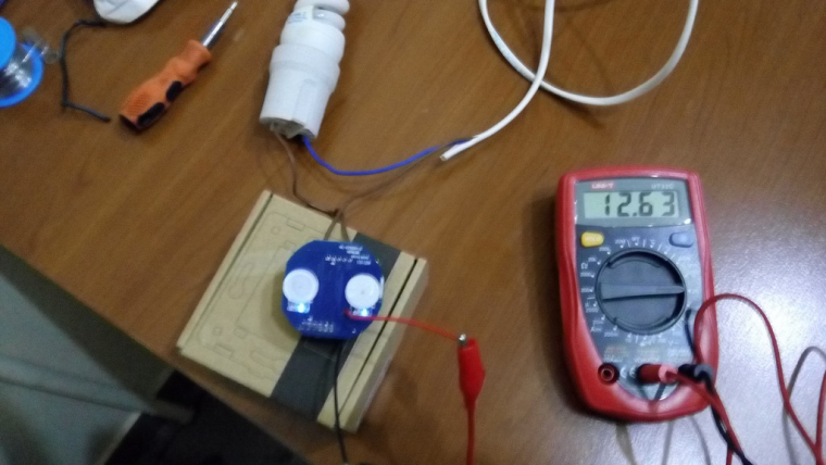
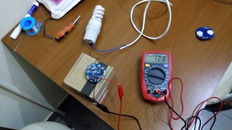
performed first tests on the switch power supply/relays board and the results are very promising so far as you can see here- switch is OFF: the so called 12V line gives us 12.63V
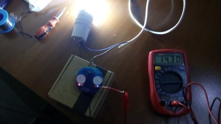
2.switch is ON: the so called 12V line gives us 14.3V
-
switch power supply/relays board ONLY(without the front plate): 12.8V
-
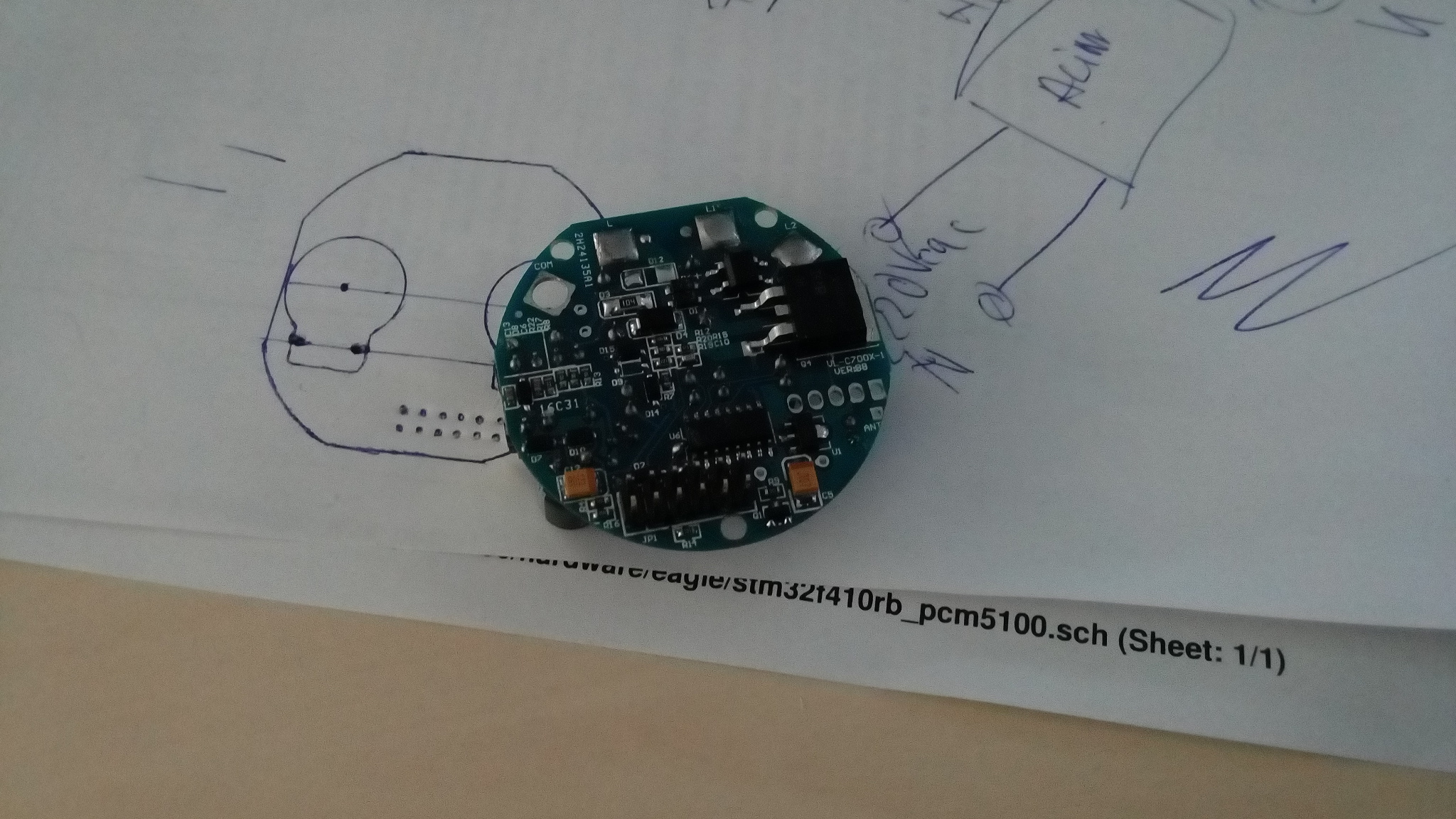
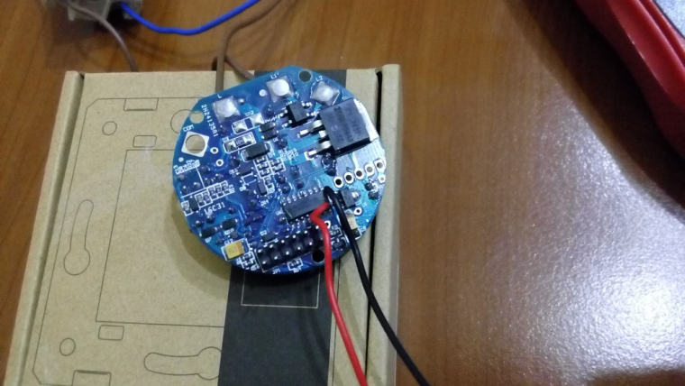
a closer look at the switch power supply/relays board and wiring for the unregulated 12V input
-
switch power supply/relays board with attached dc-dc step down converter for ~3.3V output
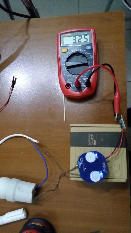
The above scenarios were tested with and without the front plate and I achieved the same and constant results on the dc-dc step down converter output: a steady 3.25V(as I managed to get by adjusting the on board trimmer). The DC-DC step down regulator is a cheap one bought from aliexpress which does the job pretty well.
Next I will add the arduino board that I prepared for testing(with code). Basically I created a setup based on:
- Arduino pro mini @ 8MHz/3.3V
- TTP223 touch sensor based modules
- RFM69W radio on an nrf24l01 adapter pcb board
- Breadboard and wires of course :simple_smile:
After attaching the above setup to the real livolo switch I will come back with the next set of results. Stay tuned.
- switch is OFF: the so called 12V line gives us 12.63V
-
After putting this thing to real life test...well it seems that it's not behaving as expected. Somehow it was expected actually because the standby circuit used in these Livolo switches is so weak(I think it provides a few mA - max 10mA or so). And again as expected it cannot sustain the RFM69W beast. I tried to do all kinds of things to lower the power consumption(sleeps and other things like reducing the radio TX power) but it's still unstable. I switched to NRF24L01 and tried the same stuff...this setup works better but still not enough stable. I even modified the board as suggested by this post: https://forum.mysensors.org/topic/2775/livolo-glass-panel-touch-light-wall-switch-arduino-433mhz/63 and still no luck: the system starts indeed and I can switch it wirelessly but after switching it off it dies when livolo gets back to the standby power supply. I supplemented the arduino power supply input with some high capacitors but that doesn't seem to help too much.
So for now this project is on hold unfortunately until I find another solution for the power supply part. This part kills me...why don't we have the second wire in the house besides the live wire?? I know the answer to this question but still...in some countries it is present in the house electrical wiring for the light switches.
I think you have the solution very close. I´m sure It is simply a matter of "fine-tuning" the Livolo's power circuitry so that they can provide enough energy (much more than designed) for the extra circuitry, something for which they are not prepared at all, but should not be too difficult to achieve if necessary. Considerations.
1.- The power circuit depends on the "consumption" that can be achieved over the load connected to the switch, so it is necessary to ensure that the load has enough "power draw" to allow pass through at least 100-150mA from AC which should be achieved with a load about 40/60W.
It is also something that can be compensated by adding a bypass capacitor (parallel to the load) of between 100 and 470 nf (of type X2 and 250V better 400 V to go safer), but all this is matter the try and error to achieve the target.2.- It must be able to avoid the Livolo power circuit so that additional power can be consumed without being affected by the circuit status of the switch, either in standby or active mode. In theory that can be done through the bridges @DJONvl and @Tigroenot indicates in the post you mentions https://forum.mysensors.org/topic/2775/livolo-glass-panel-touch-light-wall-switch-Arduino-433mhz/63 , and whit that should be possible to have the necessary power and several of them seems have confirmed that it is possible.
Perhaps the problem arises to be able to correctly identify which are the correct modifications to be made in each Livolo switch since there are different types of circuits according to the world region to which they are addressed and different revisions of printed circuit so it is critical and not very obvious as Identify the jumpers and connections to be modified and how the power bypass in each case must be performed in order to extract the current to feed the additional circuit.
I think the latter is the most complicated and difficult to perform correctly, but nothing compared to all the work you have already done, so I'm sure you've almost got it.
If I could help you, I suggest some posts (unfortunately only spoken in Russian ;-), o. c. you need use google translator to try to understand) where you will see in the lower page intersting people discussions that are given some patterns and ideas to modify the circuit and that seems have managed to extract required current to power additional circuits.
Http://mysku.ru/blog/aliexpress/12956.html
I also indicated the analysis (I think original) of a person who performed reverse engineering to extract the schematic circuit from the assembled Livolo switch and where it discusses some aspects of its operation that can help.
Http://we.easyelectronics.ru/Shematech/preparirovanie-sensornogo-vyklyuchatelya-livolo.html
Please do not be discouraged and persevere a little more than you already have it!
Greetings.
-
You're a genius!!! I forgot about the parallel capacitor which has to be put on the load(light bulb). I picked a 470nF and a 20W fluorescent light bulb and it works like a charm now and with RFM69W too!!!. Thanks so much for reminding me about the capacitors. Now I can continue and finish this project. Will come back later when my PCB's arrive and assemble the final product. Stay tuned.
Big congrats to @jirm, @DJONvl and @Tigroenot and the rest of the community of course which contributed with the knowledge to make this possible. This is really a big step ahead. -
Indeed it is !
Livolo also sells some "lighting adapters" that do the same job than the parallel capacitor but a bit more advanced and I think a bit more efficient. These are probably not necessary all the time, I had no problem to power a pro-mini and a nrf24 from the livolo switch when I tried. But as I have a US/AU version made to have up to 4 relays the supply might be a little bit more tolerant.
https://www.aliexpress.com/store/product/Free-Shipping-Livolo-Lighting-Adapter-The-Saviour-Of-The-Low-wattage-LED-Lamp-White-Plastic-Materials/500715_1630968581.html?spm=2114.12010612.0.0.cTB2pcI started to solder my first PCBs for the US/AU switches, I suffered with my first SMD atmega but it's in place and running fine now :D I hope to finish a first board and test it on a real livolo switch next week.
-
Indeed it is !
Livolo also sells some "lighting adapters" that do the same job than the parallel capacitor but a bit more advanced and I think a bit more efficient. These are probably not necessary all the time, I had no problem to power a pro-mini and a nrf24 from the livolo switch when I tried. But as I have a US/AU version made to have up to 4 relays the supply might be a little bit more tolerant.
https://www.aliexpress.com/store/product/Free-Shipping-Livolo-Lighting-Adapter-The-Saviour-Of-The-Low-wattage-LED-Lamp-White-Plastic-Materials/500715_1630968581.html?spm=2114.12010612.0.0.cTB2pcI started to solder my first PCBs for the US/AU switches, I suffered with my first SMD atmega but it's in place and running fine now :D I hope to finish a first board and test it on a real livolo switch next week.
The relay used on these boards is the latching type. So it doesn't require much power to operate as it needs only a small duration voltage pulse to energize the corresponding coil(set or reset) and the rest is done by the integrated mechanical part in combination with some magnet so that it stays "latched" in one position. This way we don't need to keep the relay coil energized all the time in order to keep the contacts ON so it's a let's say "low power" relay. The disadvantage is that it needs 2 digital pins to operate it if it's the 2 coils version and a H-bridge I presume if it's the single coil version(this one needs the polarity reversed on the coil in order to latch between the ON/OFF state). And another thing is that because of the above mentioned "latching" property this device has "memory" so we need to take care of that too as to not leave the lights ON for example in case of power failure. This can be easily achieved when the microcontroller starts in the "setup" routine by resetting the relays(I already tested this part and it works).
Now I know that these livolo switches have 2 more pins on the boards connector marked V_SENSE1 and V_SENSE2 if I remember well - I presume that those provide some voltage based on the relays state ON or OFF? I didn't tested that yet so I'm not sure if it's true(it would be great to be so as we can query the switch state using those signals instead of creating some variables in the sketch to hold the relays state).
-
Yes I have noticed they are latched as on the US/AU switches the MCU doesn't have enough pins and it needs a decoder to control up to 8 latches with 3 MCU pins. But still there are 4 leds to switch on, and maybe a bit more reserve power in case you switch all switches in a very short time ? Or maybe it's just that I use them with bulbs/tubes that allow more current to pass through :)
It contains a bunch of components, it's more than just a capacitor. You can have a look here :
http://mysku.ru/blog/aliexpress/30094.html -
Yes I have noticed they are latched as on the US/AU switches the MCU doesn't have enough pins and it needs a decoder to control up to 8 latches with 3 MCU pins. But still there are 4 leds to switch on, and maybe a bit more reserve power in case you switch all switches in a very short time ? Or maybe it's just that I use them with bulbs/tubes that allow more current to pass through :)
It contains a bunch of components, it's more than just a capacitor. You can have a look here :
http://mysku.ru/blog/aliexpress/30094.htmlIndeed it seems that it's not just a simple capacitor inside it. Well the whole purpose of it and also when using a capacitor in parallel with the light bulb is to have more current to pass through the series circuit so that the livolo power supply can provide much more power in the standby mode(when the light is OFF).
Take for example the simple capacitor: we know that when used in AC circuits it has a reactance which is kind of a resistance with a value that depends on the capacity and AC frequency. So if it's mounted in parallel with the load it reduces the overall resistance that the light bulb may impose in the circuit. We know that in a parallel circuit the lowest resistance element wins right? This way if we choose a proper value capacitor we can reduce the overall resistance in the circuit so more current can flow - this is needed in the OFF state as the standby circuit is weaker in this case. In the ON state the load is powered and much more current flows in the series circuit so no problems here. The only drawback in the ON state is to not use a too big capacitor so that it draws more current than necessary (it's in parallel with the load remember?) - in this case the light bulb could not work properly as it's bypassed by the capacitor so to speak. I used a 470nF capacitor with enough voltage rating and it works just fine...I will test with a 100nF capacitor too.
-
Yes I have noticed they are latched as on the US/AU switches the MCU doesn't have enough pins and it needs a decoder to control up to 8 latches with 3 MCU pins. But still there are 4 leds to switch on, and maybe a bit more reserve power in case you switch all switches in a very short time ? Or maybe it's just that I use them with bulbs/tubes that allow more current to pass through :)
It contains a bunch of components, it's more than just a capacitor. You can have a look here :
http://mysku.ru/blog/aliexpress/30094.htmlI think that device you sent earlier it's a power MOSFET based circuit. A MOSFET it's basically a voltage controlled resistance so it's a more "dynamic" way of controlling the bypassing "resistance" on the light bulb than using a simple capacitor which has a fixed reactance(AC equivalent resistance). I can see on the bottom side that it has some diodes which are needed because the MOSFET normally works in DC circuits so by using those we can assure that the current flows through it in one way as required. One example of such a circuit is here: http://forum.allaboutcircuits.com/blog/controlling-an-ac-load-with-a-mosfet.518
The above circuit is for controlling AC loads using MOSFET's so it's not related to our case but to ensure correct DC functionality I think they use the same ideas with diodes. The rest of components are for MOSFET gate proper driving I presume.
Another advantage of using that mosfet based circuit is that it's much smaller than using single capacitors. Capacitors tend to be bulky as the capacitance and/or voltage rating increases. Just my 2 cents here.
-
I think that device you sent earlier it's a power MOSFET based circuit. A MOSFET it's basically a voltage controlled resistance so it's a more "dynamic" way of controlling the bypassing "resistance" on the light bulb than using a simple capacitor which has a fixed reactance(AC equivalent resistance). I can see on the bottom side that it has some diodes which are needed because the MOSFET normally works in DC circuits so by using those we can assure that the current flows through it in one way as required. One example of such a circuit is here: http://forum.allaboutcircuits.com/blog/controlling-an-ac-load-with-a-mosfet.518
The above circuit is for controlling AC loads using MOSFET's so it's not related to our case but to ensure correct DC functionality I think they use the same ideas with diodes. The rest of components are for MOSFET gate proper driving I presume.
Another advantage of using that mosfet based circuit is that it's much smaller than using single capacitors. Capacitors tend to be bulky as the capacitance and/or voltage rating increases. Just my 2 cents here.
Hi @mtiutiu, You are the genius !!!.
I'm really happy to hear that you've finally achieved the desired results. Believe me that joy is mine if on anything but minimal I have contributed to you can achieve the desired goal.
I firmly believe that your development is the one that with difference and from my modest point of view has the key to success both because of its general approach and the fabulous development that I see you are performing in the accurate design of the additional circuit and I am sure that this design will be the future reference to give the Livolo's the possibility about true bidirectional RF control.Regarding the circuit that Livolo sells to avoid the problems of switch flickering by low power loads (less than 3W) this is a circuit with active components and is not a circuit designed to provide more power but to guarantee the switch of a " minimum " but regulated and constant current and providing it with better immunity because the current fluctuations caused by some electronic loads (led and similar) when they are at rest.
So it is not at all something that can be compared to the function of the capacitor in parallel to the load that provides an absolute increase of the current flow through the load circuit (and therefore of the switch) due to its behavior resistive in AC (more correctly its impedance), and this last is the characteristic that here we are looking for.
Just point out that a couple of details regarding the use of a capacitor in this way, and is that the consumption will be constant activated the load or not although we speak of an increase in very low consumption (100ma @ 220V = 2.5W aprox) but should not be neglected if we intend to "modify" by this way a relatively high number of loads and in this cases I think at least imposes a previous calculation of the constant power that we will increased because of add a "pile" of parallel load caps.
Also not should we lose on sight the fact that we will introduce a reactive component (reactive power) that can affect the character of our electrical installation and that as I say if it is used generically in many loads it is necessary to calculate its effect in our installation to avoid some displeasure with our electric company and their invoices.Finally let's do some simple math to calculate a capacitor value that might be appropriate.
Thus, the capacitive reactance is expressed as Xc = 1 / (w * C) where w is omega (equals 2 * pi * f, where f is the frequency) and C is the capacity in farads.
So if we wanted to have 20ma at 220V we would need a resistance of 4K (obviously I not do here this calculation of the simple ohm law) and therefore in my country that we have 50Hz frequency the capacity we would need would be C = 1 / (w * Xc) => C = 1 / (314 * 4000 ) = 729nFSumming up the capacitor you have tested on 470nf gives you a constant current of about 15ma when the circuit is in standby (load off), and don't forget we have a capacitor so we can achieve much more current from his reserve (this is for what was designed) and we can manage the current peak draw when RF transceiver are full active working on sending (Hope RFM69W/HW typically have current peaks over 30-40 ma on 100-200ms duration on sending cicles at full RF power) and seeing all seams should be enough to power any RF transceiver and a low power mcu if its consumption is well controlled by its proper use.
With this capacitor we are increasing the consumption of the load circuit in only about 0.5W, but let's not forget that this will be constant consumption in 24/365 hours / days a year.
So I keep close tuned with your evolution here.
Best regards
Hello! It looks like you're interested in this conversation, but you don't have an account yet.
Getting fed up of having to scroll through the same posts each visit? When you register for an account, you'll always come back to exactly where you were before, and choose to be notified of new replies (either via email, or push notification). You'll also be able to save bookmarks and upvote posts to show your appreciation to other community members.
With your input, this post could be even better 💗
Register Login