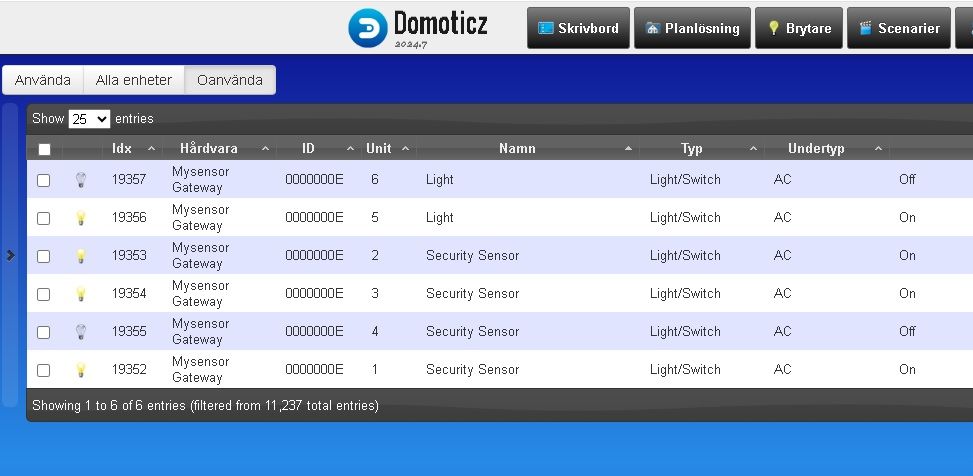
Navigation

    • Register
    • Login
    • Search
    • OpenHardware.io
    • Categories
    • Recent
    • Tags
    • Popular
    1. Home
    2. Tags
    3. mysensors
    Log in to post

    • William Meli

      Car battery health monitoring and alerts system with IoT integration
      My Project • mysensors temperature led ota wifi iot battery powered bluetooth ble low power battery sensor rgb motion sensor hardware fota 3d print mcu battery monitor enclosure battery voltage measurement pcb layout 32bit software antenna bluetooth low energy pcb manufacturi pcba dc-to-dc alarm system • • William Meli  

      5
      5
      Votes
      5
      Posts
      85
      Views

      William Meli

      @NeverDie Thx for appreciating the work done. There will also be an open source part in the future. When and how extensive the open source part will be, remains to be seen. The release of certain information (block diagram, ..., in this post) is related to those open source parts. There are some OBD solutions, however most of them (in my experience) give back low frequency data put by the car manufacturer on the OBD-bus (CAN, ...). Therefore transients evolving directly from the battery could only be recorded if the manufacturer sends those data accordingly on the bus. Due to the small bandwidth(also because of other car data that have to be sent, ...), such battery data are sent more often once per second or less. Fast battery events (i.e. cranking events, ...) are therefore imperceptible. Unless the manufacturer processes the fast events and then sends them (once per second or less), which is very unlikely if the manufacturer does not market this feature itself. Third parties devices for high frequency sensing costs several hundreds dollars. In my experience, important battery states (especially the fast ones) are recorded by measuring and processing corresponding data directly on the battery. I agree with you about the limits related to the communication over Bluetooth. But i think Bluetooth 5.0 will improve a lot. However, WiFi will always remain an important option due to the high data throughput. The combination of both (BLE & WiFi), especially with regard to energy consumption, will gain in importance.
    • KevinT

      Gateway report all nodes rf power
      General Discussion • mysensors • • KevinT  

      4
      0
      Votes
      4
      Posts
      41
      Views

      mfalkvidd

      @KevinT every time, yes. I don't know the relation to processing.
    • frydrik

      Power Meter Pulse Sensor for multiple meters
      My Project • mysensors • • frydrik  

      1
      0
      Votes
      1
      Posts
      28
      Views

      No one has replied

    • Sameh Bouhafs

      pressure sensor MPS20N0040D
      My Project • mysensors • • Sameh Bouhafs  

      3
      0
      Votes
      3
      Posts
      25
      Views

      mfalkvidd

      When you post the sketch, please post the text, not a photo of the screen.
    • openhardware.io

      💬 MyGateway
      OpenHardware.io • mysensors gateway rfm69 ethernet poe • • openhardware.io  

      4
      0
      Votes
      4
      Posts
      87
      Views

      hlehoux

      This project is very cool! I received my pcbs to try it this morning , i'll tell you if i can make it work
    • NielBierman

      FOTA possibilities for remote sensor network
      General Discussion • mysensors • • NielBierman  

      2
      0
      Votes
      2
      Posts
      37
      Views

      TRS-80

      In general, yes, the MySensors framework (library?) should support FOTA a couple different ways (read more at link). Were you aware of this, or is there some problem with your particular hardware? @NielBierman said in FOTA possibilities for remote sensor network: Raspberry pi I don't know yet whether you even need to change your gateway from microcontroller (uC) to Single Board Computer (SBC) or not. However if you do (or are looking for a controller, or whatever), by all means, please do yourself (and all of us) a favor and do a little more research as there are lots of better options out there for SBC nowadays, than RPi! For me, uC have been fine for gateway although I do use some SBC for controllers, MQTT broker, and various other GNU/Linux based servers/services and they are wonderful for that. But perhaps your needs are different from mine.
    • openhardware.io

      💬 MySensors RS-485 Universal Module
      OpenHardware.io • mysensors sensor rs485 button 485 wall plate • • openhardware.io  

      5
      0
      Votes
      5
      Posts
      31
      Views

      Anticimex

      @YuryPol as far as I know, all licenses require some form of documentation. In all cases I know of, this is documented with the license or on the licenses official site.
    • GLAB

      Compatibility between mysensors and RF24 library on same node.
      General Discussion • mysensors arduino rf24 • • GLAB  

      13
      0
      Votes
      13
      Posts
      89
      Views

      zboblamont

      @GLAB No worries, was in a similar situation.. My perspective was on what the Node could be made to provide, not what could be done within Domoticz to address the requirement - eg Had heard of Dummy counters but had no experience nor understood their purpose, nor had ever used scripts. I had been sending a logical ON/OFF as well as a cumulative total from the Node and hit the same hair-pulling scenario as yourself. Now only the ON/OFF is sent and the short script makes the transposition within Domoticz to a dummy meter (I think kWhr) using the internal clock in Domoticz. Have fun
    • Rysiek

      MySensor Network on RS485 - only single node visible
      Troubleshooting • mysensors • • Rysiek  

      12
      0
      Votes
      12
      Posts
      126
      Views

      rejoe2

      Having a deeper look at resistor values is always a good idea. Indeed, optimal values depend on a lot of parameters. You might find a helpful tool for getting the best values for your setup here: http://www.alciro.org/tools/RS-485/RS485-resistor-termination-calculator.jsp
    • openhardware.io

      💬 MySensors Battery node 2xAAA for SI/BME/SHT
      OpenHardware.io • mysensors temperature & humidity sensor battery sensor • • openhardware.io  

      1
      0
      Votes
      1
      Posts
      25
      Views

      No one has replied

    • openhardware.io

      💬 Minimal LiPo powered Arduino Pro Mini + RFM95 MySensors node
      OpenHardware.io • mysensors pro mini bme280 rfm95 • • openhardware.io  

      22
      0
      Votes
      22
      Posts
      146
      Views

      evb

      @Joost, bumping
    • Shiny

      Which presentation to use for a Turbidity Sensor?
      My Project • mysensors • • Shiny  

      1
      0
      Votes
      1
      Posts
      20
      Views

      No one has replied

    • openhardware.io

      💬 MySensors compact (junction box) relay
      OpenHardware.io • mysensors relay 220v • • openhardware.io  

      1
      1
      Votes
      1
      Posts
      25
      Views

      No one has replied

    • openhardware.io

      💬 mySensors Hit Train
      OpenHardware.io • mysensors christimas train • • openhardware.io  

      1
      0
      Votes
      1
      Posts
      134
      Views

      No one has replied

    • openhardware.io

      💬 MySensors Linky
      OpenHardware.io • mysensors arduino mysensor arduino pro mini linky edf enedis • • openhardware.io  

      12
      0
      Votes
      12
      Posts
      575
      Views

      secator

      thanks for you reply Fumée Bleue.
    • openhardware.io

      💬 "Drömsyn" Weather prediction lamp
      OpenHardware.io • mysensors weather • • openhardware.io  

      2
      1
      Votes
      2
      Posts
      182
      Views

      skywatch

      @openhardware-io That looks great! - Perhaps they could make a version for the UK market called "regnsyn" ??? ;0
    • openhardware.io

      💬 MySensors Watermeter
      OpenHardware.io • mysensors arduino mysensor water watermeter • • openhardware.io  

      1
      0
      Votes
      1
      Posts
      179
      Views

      No one has replied

    • openhardware.io

      💬 NRF52 In Wall-Dimmer
      OpenHardware.io • mysensors led dimmer fl5150 • • openhardware.io  

      1
      1
      Votes
      1
      Posts
      321
      Views

      No one has replied

    • openhardware.io

      💬 Usb serial Mysensors Gateway
      OpenHardware.io • mysensors gateway mysensor passerelle de mysensors • • openhardware.io  

      1
      0
      Votes
      1
      Posts
      253
      Views

      No one has replied

    • openhardware.io

      💬 Radio Node
      OpenHardware.io • mysensors nrf24l01+ battery atmega328p tp4056 lipo • • openhardware.io  

      2
      0
      Votes
      2
      Posts
      441
      Views

      Anticimex

      Please add the documents required by the CERN license used.
    • openhardware.io

      💬 MySensors Nrf24/RFM Serial/Ethernet GW Shield (for Uno)
      OpenHardware.io • mysensors rfm69 nrf24l01+ • • openhardware.io  

      28
      0
      Votes
      28
      Posts
      591
      Views

      hlehoux

      Hello, i'm making some progress; received the components this week. Unfortunately it doesn't work... yet For now i have SanityCheck failure in to logs. I'm afraid my soldering of all these little components is not good. I tested with a multimeter the 4 pins and i have continuity on one of them but maybe not the others so i guess i will have to try remelting all these small regulators ???
    • openhardware.io

      💬 MySensors Low-power Multi-function node on CR2032
      OpenHardware.io • mysensors nrf24l01+ atsha204a si7021 node at25df512c • • openhardware.io  

      15
      0
      Votes
      15
      Posts
      2548
      Views

      Fanfan

      @rvendrame sorry, I did not see your comment. Yes, it is VERY valuable. Thanks a lot
    • openhardware.io

      💬 MyThermostat
      OpenHardware.io • mysensors arduino rfm69 thermostat pid heater • • openhardware.io  

      5
      1
      Votes
      5
      Posts
      1161
      Views

      Gerator

      @kimot I am not handling that situation. I'm taking for granted ssr will do his job. Maybe there's some ssr safety topic I'm unaware? Suggestions for a v3.0 are welcome. About the temperature measuring... I use two sensors. The one in the board protects electronics from temperatures beyond design (60°C). It's near the ssr because the ssr's derating curve is the most limiting condition. The control sensor is placed in the bottom of the heater. It connects to the board through a 3 pin header connector.
    • openhardware.io

      💬 MDMSMotion
      OpenHardware.io • mysensors sensor motion majordomo • • openhardware.io  

      1
      1
      Votes
      1
      Posts
      388
      Views

      No one has replied

    • openhardware.io

      💬 NRF24L01 shield for Arduino Uno (for MySensors gateway)
      OpenHardware.io • mysensors arduino gateway nrf24l01 shield • • openhardware.io  

      1
      0
      Votes
      1
      Posts
      489
      Views

      No one has replied

    • openhardware.io

      💬 MySensors InCan double light switch
      OpenHardware.io • mysensors nrf24l01 relay switch light hlk-pm01 acdc in-wall • • openhardware.io  

      22
      0
      Votes
      22
      Posts
      2415
      Views

      insectteam

    • openhardware.io

      💬 MSMDLed
      OpenHardware.io • mysensors controller led • • openhardware.io  

      1
      0
      Votes
      1
      Posts
      533
      Views

      No one has replied

    • openhardware.io

      💬 RS485 4RelayDin Shield
      OpenHardware.io • mysensors relay rs485 sensor network current sensor acs712 • • openhardware.io  

      1
      1
      Votes
      1
      Posts
      551
      Views

      No one has replied

    • openhardware.io

      💬 NRF24 to RFM69 adapter
      OpenHardware.io • mysensors nrf24l01 rfm69 nrf24 radio • • openhardware.io  

      5
      0
      Votes
      5
      Posts
      1247
      Views

      sineverba

      @alowhum thank you
    • openhardware.io

      💬 Mini Dimmer Box
      OpenHardware.io • mysensors atsha204a ota dimmer power supply acdc rgb acs712 • • openhardware.io  

      2
      1
      Votes
      2
      Posts
      1117
      Views

      Koresh

    • openhardware.io

      💬 Safe relay node
      OpenHardware.io • mysensors nrf24l01 relay atmega328 acs712 safe ssd ds18s20 moc3063-m bta206 smart nrp05-a-05d ap9930gm1 • • openhardware.io  

      17
      1
      Votes
      17
      Posts
      3034
      Views

      jeremushka

      Hello Berk, Is it possible for you to share your schematic for this project please? especially the power part?
    • openhardware.io

      💬 EASY PIR multisensors box
      OpenHardware.io • mysensors rfm69 temperature light pir si7021 dc-dc bh1750 longlife • • openhardware.io  

      23
      4
      Votes
      23
      Posts
      4718
      Views

      yury

      ESUN flex filament used.
    • openhardware.io

      💬 MySensors singleLED
      OpenHardware.io • mysensors rfm69 led • • openhardware.io  

      5
      0
      Votes
      5
      Posts
      1698
      Views

      ThetaDev

      @krisztian Hi krisztian, the singleLED board - as its name suggests - features only one LED output. If you want to have a setup with multiple LED strips you need to design a board with multiple outputs. I have already designed a board with 4 outputs, but I haven't built it. In terms of software you need to register multiple sensors in your program like this: #define numCh 4 //the number of outputs const byte ledPins[] = {9,6,5,3}; byte ledLevel[numCh]; boolean ledDimWay[numCh]; //in the setup function request the dim levels from the gateway for(byte i=0; i<numCh; i++) request(i, V_DIMMER); //in the presentation function register multiple lights for(byte i=0; i<numCh; i++) present(i, S_DIMMER); //if you receive a signal, you need to check for the sensor id setLED(message.sensor, requestedLevel); //to set the LED level (function: setLED) you need to use the sensor id to determine brightness and pin //Fade LED to set level int delta = (level - ledLevel[child]) < 0 ? -1 : 1; //Write to LED analogWrite(ledPins[child], map(ledLevel[child],0,100,0,255)); I will probably publish the whole code once I have built and tested the 4LED controller (i call it "MySensors rainbowLED") Hope I could help you ThetaDev
    • openhardware.io

      💬 simple MySensors MultiSensor Board
      OpenHardware.io • mysensors sensor htu21d ldr • • openhardware.io  

      6
      0
      Votes
      6
      Posts
      2158
      Views

      momo90

      Hi! I have the same problem as terxw. allpcb.com is missing the "NC drill date". Unfortunately I am not able to create this on my own. Can anybody upload this file? Thanks
    • openhardware.io

      💬 ESP8266 Gateway
      OpenHardware.io • mysensors rfm69 nrf24l01+ esp8266 mysensors gateway oled display epaper • • openhardware.io  

      2
      0
      Votes
      2
      Posts
      1203
      Views

      MiKa

      Is this design for some existing enclosure?
    • openhardware.io

      💬 LED RGBW Controller
      OpenHardware.io • mysensors nrf24l01 atsha204a led rgb w25x40clsnig rgbw • • openhardware.io  

      4
      0
      Votes
      4
      Posts
      1838
      Views

      giltesa

      I have already published all the documentation, on my website, GitHub and openhardware.io For now I leave the node as finished. https://www.youtube.com/watch?v=kzpNkBX-3T0
    • openhardware.io

      💬 Multi-purpose sensor
      OpenHardware.io • mysensors nrf24l01 sensor atsha204a htu21d bh1750 w25x40clsnig • • openhardware.io  

      2
      0
      Votes
      2
      Posts
      1104
      Views

      giltesa

      I have published all the documentation in a Github repository. If someone wants to make PCBs, I recommend that you wait a little longer until you receive my PCBs and try them. https://github.com/giltesa/SmartHome
    • openhardware.io

      💬 Wireless remote control
      OpenHardware.io • mysensors nrf24l01 switch remote control • • openhardware.io  

      4
      0
      Votes
      4
      Posts
      1889
      Views

      giltesa

      Hi @talhatec , The remote controls work well. 4 months ago I installed a new battery and from time to time I press the button to check if they continue with battery, they sleep correctly. I remain pending to change the RF antenna for a better one and to improve some failures in the connectors of the battery that at the moment are very fragile (the pad has little copper). The casing can be purchased online https://www.ebay.com/itm/Bluetooth-4-0-GPS-Tracker-Locator-Smart-Alarm-Anti-lost-Device-Self-Portrait-SC/401394156488 For now the project is stopped, I want to test the Aqara sensors (I buy them this week), in any case the domotics is now my lowest priority.
    • openhardware.io

      💬 Wireless Touch Switch: Triac Model - (For Livolo crystals)
      OpenHardware.io • mysensors nrf24l01 relay switch light atmega328p light switch livolo w25x40clsnig • • openhardware.io  

      3
      0
      Votes
      3
      Posts
      1491
      Views

      giltesa

      I have published all the documentation in a Github repository. If someone wants to make PCBs, I recommend that you wait a little longer until you receive my PCBs and try them. https://github.com/giltesa/SmartHome
    • openhardware.io

      💬 Wireless Touch Switch: Relay Model - (For Livolo crystals)
      OpenHardware.io • mysensors nrf24l01 relay switch light light switch livolo • • openhardware.io  

      30
      1
      Votes
      30
      Posts
      7316
      Views

      giltesa

      @dzungpham0703 I buy them on Aliexpress: https://www.aliexpress.com/wholesale?catId=0&initiative_id=SB_20180706102504&SearchText=HTTM If you apply hot air it is easy to take off the white "double sided tape" and the plastic.
    • openhardware.io

      💬 In-wall scene controller OLED keypad
      OpenHardware.io • mysensors scene controller wall switch oled display keypad • • openhardware.io  

      5
      0
      Votes
      5
      Posts
      2014
      Views

      dbemowsk

      I have finally gotten back to this project and created a working sketch that communicates with my Vera controller. I have this set up as a 3 button on/off (6 switches on the board) and have that working successfully with Vera. I also have my Vera sending temperature data back to the OLED display. It alternates between the outside temp and room temp for my master bedroom where the switch is located. I have posted the Arduino sketch under source code here.
    • openhardware.io

      💬 MDMScreen
      OpenHardware.io • mysensors arduino nrf24l01 rfm69 atmega328p lcd nextion spi flash touchscreen • • openhardware.io  

      2
      2
      Votes
      2
      Posts
      998
      Views

      Ivan Z

      Please append support RS485
    • openhardware.io

      💬 In-wall scene controller PSU
      OpenHardware.io • mysensors power supply scene controller wall switch dbemowsk • • openhardware.io  

      7
      0
      Votes
      7
      Posts
      1595
      Views

      dbemowsk

      @bisschopsr I now have the schematics posted for all of my boards. I also posted another board for my in-wall scene controller line. Is there any other pics or information that you think might be useful to others for any of these boards?
    • openhardware.io

      💬 Floor heating controller
      OpenHardware.io • mysensors temperature thermostat • • openhardware.io  

      8
      1
      Votes
      8
      Posts
      2613
      Views

      gohan

      You would use PID if you have a temperature feedback from the rooms, but in your case you are not interested so it doesn't matter much. Sure turning off pump when not needed is a good thing. I have colleague that also bought a few netatmo devices to control floor heating of some zones of his house and he is very happy.
    • openhardware.io

      💬 RFM69 Raspberry PI Zero(W) Shield(HAT)
      OpenHardware.io • mysensors rfm69 raspberry pi • • openhardware.io  

      15
      0
      Votes
      15
      Posts
      4066
      Views

      gohan

      @neverdie that's quite some money...
    • openhardware.io

      💬 NRF51822 Livolo 1 channel 1 way EU switch(VL-C700X-1_Ver_C2)
      OpenHardware.io • mysensors livolo nrf51 • • openhardware.io  

      11
      0
      Votes
      11
      Posts
      2698
      Views

      Yveaux

      @andreas-sieber The white circle on the PCB you mean? IMO That's silkscreen indicating the touch area.
    • openhardware.io

      💬 NRF51822 Livolo 2 channel 1 way EU switch(VL-C700X-1_Ver_C2)
      OpenHardware.io • mysensors livolo nrf51 • • openhardware.io  

      3
      0
      Votes
      3
      Posts
      1267
      Views

      mtiutiu

      @shabba Hi, unfortunately I don't have time and patience for doing BOM's on all of my projects but in this case it's not very hard as the external component count is greatly reduced by using the NRF51822 RF SOC which is a PTR5518 module from Aliexpress. Other than that there is the Microchip touch sense controller - MTCH105 and the usual smd resistors(0603) and caps. Other than that you're not forced to use and solder the onboard dc-dc converter so you don't have to worry about those components - you just need to solder the 3V_EN jumper to use the Livolo 3V output coming from the main relays/power supply board. nRF51822 Bluetooth 4.0/ 4.2 Module Ultra small size smaller than CR2032 coin battery PTR5518 BLE module XUNTONG $24.95
    • hek

      💬 Dollhouse
      Announcements • mysensors nrf24l01+ raspberry pi maker faire • • hek  

      2
      0
      Votes
      2
      Posts
      1157
      Views

      dakipro

      Awesome project, I wish I made something like this. (I actually wanted to make something like this when I was in school) Very clean and nice presentation and realization, with a lot of attention to details. All is very realistic, I can imagine that it took quite some time making it. Thanks for sharing the details!
    • openhardware.io

      💬 Dollhouse wireless node
      OpenHardware.io • mysensors nrf24l01+ • • openhardware.io  

      8
      1
      Votes
      8
      Posts
      2218
      Views

      Yveaux

      @pihome few months tops, I think.
    • openhardware.io

      💬 MDMSNode "Lighting" Rev 1.1
      OpenHardware.io • mysensors arduino nrf24l01 atsha204a ota atmega328p rfm69hw hlk-pm01 lighting triac • • openhardware.io  

      9
      0
      Votes
      9
      Posts
      2606
      Views

      jeremushka

      @kalina, Thanks. So it will not work for my configuration. Wall switch (push button) is already installed. No possibilities to draw more electrical wires. Moreover, if i put the board near the light, i have just the Neutral and the return wire from the wall switch. No Live wire to power on the mysensors board. I think in my ase the best way is to manage everything in my garage in the electrical main board where all the wires are mapped. I can get L + N for mysensors power supply. And i can continue to reuse the original wall switch independently of the Mysensors board.
    • openhardware.io

      💬 Uniflächentaster PCB
      OpenHardware.io • mysensors temperature battery humidity switch • • openhardware.io  

      2
      0
      Votes
      2
      Posts
      2048
      Views

      Blauhorn

      Hello Tilman, this is really a very nice design. I have ordered a pack of PCBs from elecrow, based on your gerber files, and have a few questions: in your BOM you have listed 5 smd-capacitors and 7 smd resistors, but on the PCB i have solderpads for 6 capacitors and 8 resistors. Can you just explain? is there a uniflächentaster-model for 2 ways? i think i have to flash the bootloader first, do you have a tutorial for this, and a sample-sketch for the board? Thank you very much
    • openhardware.io

      💬 Door/Windows AAA
      OpenHardware.io • mysensors nrf24l01 mysensor battery sensor window door contact • • openhardware.io  

      7
      0
      Votes
      7
      Posts
      2599
      Views

      arden

      id also second the use of 18650s
    • openhardware.io

      💬 Battery powered glass touch switch
      OpenHardware.io • mysensors contest2017 switch waf remote • • openhardware.io  

      21
      0
      Votes
      21
      Posts
      6858
      Views

      Wesley

      @Nca78 Do you tested this board, if yes, did it work? And which CS capacitors did you use?
    • openhardware.io

      💬 BlackCircle Sensor - High "WAF" Temp/Hum. sensor
      OpenHardware.io • mysensors temperature humidity contest2017 waf • • openhardware.io  

      13
      0
      Votes
      13
      Posts
      3765
      Views

      Nca78

      @bisschopsr said in BlackCircle Sensor - High "WAF" Temp/Hum. sensor: Hi All, Like the design thinking of this, although an older topic I did manage to get me one of these dishes. After taking it apart, I have one question that came to mind. Is the ventilation in the dish enough for the humity sensor? Is there any experience with that after running this sensor for a while? Thx Ralph Hello, yes I think it's enough, in fact there's much more ventilation than in many commercial sensors which only have a small hole. But it's a good test to make, I'll try to compare to a sensor out of it's enclosure to see if there's significant difference or delay.
    • openhardware.io

      💬 MySensors Easy Pro Mini
      OpenHardware.io • mysensors contest2017 atsha204a ota • • openhardware.io  

      7
      1
      Votes
      7
      Posts
      2733
      Views

      terxw

      Hello, can you post BOM please, according to schematics tantalum schould be 100uF bat tantalum cap in picture is 4.7uF
    • openhardware.io

      💬 OH Easy Advanced Gateway
      OpenHardware.io • mysensors contest2017 • • openhardware.io  

      7
      0
      Votes
      7
      Posts
      2453
      Views

      Terrence

      @LastSamurai Thanks, it looks great.
    • openhardware.io

      💬 Dual SSR Light actuator shield for NModule
      OpenHardware.io • mysensors relay contest2017 light nmodule ssr • • openhardware.io  

      1
      0
      Votes
      1
      Posts
      863
      Views

      No one has replied

    • openhardware.io

      💬 NModule PIR sensor shield
      OpenHardware.io • mysensors contest2017 pir nmodule am312 am612 • • openhardware.io  

      13
      0
      Votes
      13
      Posts
      3376
      Views

      NeverDie

      @Nca78 FWIW, I used 1.55mm holes. There may be no perfect diameter since we don't even know for sure yet which lens will turn out best.
    • openhardware.io

      💬 NModule MiLight bridge shield
      OpenHardware.io • mysensors contest2017 nmodule milight • • openhardware.io  

      3
      0
      Votes
      3
      Posts
      1374
      Views

      Nca78

      Hello @reinhold, yes the PCB works, I have assembled one and tested it for basic function (not all buttons and leds) but I have stability problem that comes from the software, I put it aside to do other things and didn't have time to go back to it, if there is some interest for it I will find some time and finish at least a basic script.
    • openhardware.io

      💬 NModule Two buttons capacitive touch switch shield
      OpenHardware.io • mysensors contest2017 switch nmodule capacitive touche • • openhardware.io  

      7
      0
      Votes
      7
      Posts
      2570
      Views

      Nca78

      Made a first print but setting for this filament are clearly wrong as the print quality sucks
    • openhardware.io

      💬 NModule DC Fan / PWM shield
      OpenHardware.io • mysensors contest2017 nmodule fan pwm • • openhardware.io  

      4
      0
      Votes
      4
      Posts
      1345
      Views

      Nca78

      @toyman said in NModule DC Fan / PWM shield: Can the FET withstand continious 2A load? I have one meter long 5050 strip FDD8447L is rated for 15A continuous load. You don't want to try that because it's possible only with a big pad and 2oz copper PCB, but 2A will not be a problem on this board, there's plenty of margin https://isojed.nl/blog/wp-content/uploads/2013/06/FDD8447L.pdf
    • openhardware.io

      💬 MDMSNode "Lighting X2"
      OpenHardware.io • mysensors arduino nrf24l01 relay rfm69 atsha204a atmega328 ota hlk-pm01 acdc light switch • • openhardware.io  

      6
      0
      Votes
      6
      Posts
      2233
      Views

      kalina

      Hi @blackchart, Unfortunately, all devices are sold out. Further production is possible only when ordering more than 10 devices (in this case, I also can modify the device to suit your needs).
    • openhardware.io

      💬 NModule ADXL accelerometer sensor shield
      OpenHardware.io • mysensors contest2017 nmodule accelerometer adxl362 adxl adxl345 • • openhardware.io  

      4
      0
      Votes
      4
      Posts
      1525
      Views

      Fabien

      Ok thank you @Nca78
    • openhardware.io

      💬 NModule Temperature, Humidity, Light, Door sensor shield
      OpenHardware.io • mysensors temperature contest2017 light i2c nmodule door • • openhardware.io  

      41
      0
      Votes
      41
      Posts
      10456
      Views

      Nca78

      Hello, I'm thinking about upgrading this board to include pinout for LIS3DH breakout board, like this one : https://www.aliexpress.com/item/LIS3DH-Three-Converters-Motion-Accelerometer-Triaxial-Acceleration-Temperature-Sensor-Module-Development-Board-Replace-ADXL345/32840326778.html and ditch the ADXL shield as it's not a good solution, it has either the ADXL345 which uses too much power, or the ADXL362 which is ultra low power but lacks advanced functionality like tap/double tap detection. I would like to have feedback of users on this (do it sound useful ?), and also know if anyone uses the SMD footprints on the board, for leds and for reserve capacitors, as it could be a cleaner board without those footprints. I would make the following changes : put footprint for LIS3DH accelerometer along the "NModule connector" as it has too many pins to put elsewhere keep only one I2C footprint on the side, for "GY-49" MAX44009 light sensor breakout board: https://www.aliexpress.com/item/GY-49-MAX44009-Ambient-Light-Sensor-Module-for-Arduino-with-4P-Pin-Header-Module/32828654450.html temperature/humidity would be via the existing "SMD" footprint, it's not through hole but very easy to solder as it's 2.54mm pad spacing remove SMD footprints for LED, add footprint for through hole reserve capacitor, keep SMD footprints for reserve capacitors only if I have space for them shield would be a bit extended to go over the 2 M2 holes in the "power" part of the NModule, so it could be fitted with spacers and nylon screws and have stable/reliable mechanical connection between NModule and Shield. Basically this would be the footprint of the shield : So in the end it would make one shield to have Temperature/Humidity/Light/Acceleration or Temperature/Humidity/Light/Door.
    • openhardware.io

      💬 NModule
      OpenHardware.io • mysensors relay temperature humidity light pir nmodule door accelerometer touch milight • • openhardware.io  

      89
      0
      Votes
      89
      Posts
      17777
      Views

      Nca78

      @zmatokan said in NModule: @Nca78 Are you still working on this pcbs? i think it would be great to add a version that supports HiLink 220ac->5dc module on powerboard. No I'm not working on NModules anymore, I have a few old nodes using atmega/nrf24 but I switched to NRF5 for "basic" nodes now, and to ESP32 for more "advanced" stuff. NModule was designed for beginner and simple/riskless use, so I don't think adding high voltage option is a great idea, it's better to use an external power supply and connect the output to the powerboard.
    • openhardware.io

      💬 RFM69 Livolo 1 channel 1 way EU switch(VL-C700X-1_Ver_C2)
      OpenHardware.io • mysensors livolo • • openhardware.io  

      8
      1
      Votes
      8
      Posts
      2605
      Views

      jirm

      @mtiutiu Wooow Wooow Wooow ! Here they are ! This one gang you designed will be my 1st Livolo hack So many many thanks @mtiutiu Best regards
    • openhardware.io

      💬 MySWeMosIRShield - IR blaster shield for WeMos D1
      OpenHardware.io • mysensors nrf24l01 rfm69 esp8266 contest2017 wemos ir receiver ir sender • • openhardware.io  

      16
      3
      Votes
      16
      Posts
      5362
      Views

      Pio Wales

      Sorry. Disregard.
    • openhardware.io

      💬 RFM69 Livolo 2 channels 1 way EU switch(VL-C700X-1_Ver_C2)
      OpenHardware.io • mysensors livolo • • openhardware.io  

      47
      1
      Votes
      47
      Posts
      13467
      Views

      mtiutiu

      Hello all, I studied a little bit more this part of the circuit and it's a standard self oscillating flyback converter or a ringing choke converter as others call it. Indeed it provides the most compact solution for space constrained designs. But all of this comes at a cost: it's difficult to obtain a stable circuit and it has to be tuned by trial and error - at least this is what the literature says. I'm not a switching power supplies expert here(even though I want to learn more about SMPS's in general but my time is limited for now) but I've come to a conclusion: it's difficult to tune this or to change the existing circuit to accommodate the mysensors circuits power requirements. I tried various combinations using sleep schemes and to change the flyback converter components as other mentioned in the mysensors forum and indeed I can power up my custom design that is presented in this thread BUT it's NOT STABLE. From time to time the switching transistor(mje13003) burns out and this is because I removed the resistor placed at the input of this power supply - near the bridge rectifier and replaced it with a wire(this is not the same resistor as @Lukaspp replaced from the base of the transistor which is the startup resistor for the flyback converter). Now the only purpose that I imagine for this resistor is to suppress the transients - but it has a big value(100Kohm) which limits the current to a non-usable value for our purpose. I know that there are other solutions to overcome the transients but they are either bulky or too slow for this(correct me if I'm wrong here). More than that let's not forget that we have 2 power supplies here and when the lights go on the first supply(flyback) input gets shorted by the relays contact(I have the relays variant btw not the one with triac) so I'm thinking that other transients appear here as the primary inductor doesn't like that as far as I know - so I assume the above mentioned resistor of 100Kohm comes into play here too. Another role for it would be to limit the inrush currents. I played with that value too but it needs to be very low to have something stable and I got a value around 200ohms but that doesn't help as it's too low and after some time the resistor burned up and saved my transistor :simple_smile: . Now with all the tricks in the world and tuning the flyback converter to give more current this won't help as again let's not forget we have a SERIES circuit here so without external intervention we can't achieve that(only if we break somehow the laws of physics or maybe my thinking is limited :simple_smile: ). In this case the external capacitor placed across the light bulb comes into play to supply enough current to the standby circuit which is our flyback converter over here. I played with that one too and from 0,47uF I got to 4.7uF to have a decent result - but this one gets bulky and more expensive from obvious reasons. And let's not forget that the light bulb itself has some impact overall because this is the actual LOAD that we want to control and there are various light bulbs over there with various requirements. More than that they have their power supply embedded which in most of the cases is a(you guessed maybe): a self oscillating FLYBACK CONVERTER or similar. So this one too has inrush currents, transients which are sensed down the line to our dear Livolo switch and affects my custom board stability again :simple_smile: - isn't life beautiful? :simple_smile: So far these are the results of my trials and none of them proved to be stable so I kinda gave up on this and will try to use a normal powering scheme somehow(as Sonoff switches with a battery powered touch switch on the wall). Not the best solution of all but this is what you get when the infrastructure wasn't thought for this scenarios from the beginning. The Livolo guys thought of all of this I assume so that's why they stayed only with a simple circuit - a PIC mcu which maybe sleeps most of the time and a simple radio receiver which draws around 5mA or even less - so yeah that's why this works and it's stable in its original form.
    • openhardware.io

      💬 Secure 5-button Keyfob
      OpenHardware.io • mysensors atsha204a enclosure keyfob • • openhardware.io  

      2
      0
      Votes
      2
      Posts
      950
      Views

      NeverDie

      I look forward to seeing photos....
    • openhardware.io

      💬 Floating Swimming Pool Sensor (Water Quality)
      OpenHardware.io • mysensors contest2017 • • openhardware.io  

      6
      2
      Votes
      6
      Posts
      2155
      Views

      szybki946

      hello if he is going to send to domoticza PH
    • openhardware.io

      💬 Jukebox design journal
      OpenHardware.io • mysensors contest2017 bluetooth audio pt2313 jukebox • • openhardware.io  

      3
      1
      Votes
      3
      Posts
      1454
      Views

      Koresh

      Finally solved a lot of problems and checked a lot of mistakes. But now the first version of this device works almost properly :trollface: I will make a small report in the description asap
    • openhardware.io

      💬 MySensors NRF5 Platform
      OpenHardware.io • mysensors contest2017 nrf52 nrf5 nrf51 • • openhardware.io  

      210
      1
      Votes
      210
      Posts
      42787
      Views

      nagelc

      I think you can just set the I2C pins in MyBoardNRF5.h without remapping the pins in MyBoardNRF5.cpp. Look in MyBoardNRF5.h, under the Wire Interfaces section. Set SDL and SCA to 30 and 31 as appropriate for your board.
    • openhardware.io

      💬 MyQTherm - replace IQTherm heating thermostat
      OpenHardware.io • mysensors thermostat heating radiator iqtherm • • openhardware.io  

      5
      0
      Votes
      5
      Posts
      1816
      Views

      TRS-80

      @magpern said in MyQTherm - replace IQTherm heating thermostat: I actually am thinking somewhat in the line of discontinuing mysensors network. It is to much, hacks and tricks, and I forget everything in between sessions. I gave up more than once, also over period of years. Recently I came back again and decided to focus on the heart of the issue, getting my radios working and once you get over that, it starts to get fun again. I can respect if you already moved on to something else. I even cheated on MySensors and installed some 433 mhz devices too , just to get something working. You have to keep your interest in HA alive in the meantime. But the reward is great when you get MySensors working. There are "easier" solutions like Tasmota, 433mhz, etc. but not as customizable as MySensors. MySensors is for when you outgrow those other solutions and need something more custom.
    • openhardware.io

      💬 MySensors Light Switch
      OpenHardware.io • mysensors nrf24l01 hlk-pm01 solid state relay • • openhardware.io  

      10
      1
      Votes
      10
      Posts
      4839
      Views

      dbemowsk

      I like those relays. Is that 3 different switched outputs? One thing I always liked about european wall switches is that they give you more room for components. I would like to use a similar type of relay for my in-wall switches, but with the way US single gang wall boxes are, there is a pretty narrow space constraint. I might be able to fit it if I did away with the thermal fuse, but I don't want to give up tat bit of added safety just for that.
    • openhardware.io

      💬 MP3 player with RGB-signal LED (optionally battery powered)
      OpenHardware.io • mysensors contest2017 mp3 dfplayermini • • openhardware.io  

      3
      1
      Votes
      3
      Posts
      1719
      Views

      RPunkt

      Hello, I want to build this project. But I don't need to power it by batteries. Has anyone the circuit diagram (in FrizIng?) I have also the problem, that I can't see, on the breadboard picture of this project where the red wire from the battery ends after the connection to the Arduino? Does it go to the FET and the R7? Can anyone help me?
    • openhardware.io

      💬 MySensors equiped Clock Radio
      OpenHardware.io • mysensors contest2017 • • openhardware.io  

      2
      0
      Votes
      2
      Posts
      958
      Views

      hek

      Love the big red button!
    • openhardware.io

      💬 Automatic stairs led lighting arduino shield
      OpenHardware.io • mysensors arduino led automatic stairs • • openhardware.io  

      4
      0
      Votes
      4
      Posts
      2921
      Views

      Ihor

      there is no schema in this archive
    • openhardware.io

      💬 NodeManager
      OpenHardware.io • mysensors arduino contest2017 newbie battery sensor • • openhardware.io  

      196
      4
      Votes
      196
      Posts
      67315
      Views

      RPunkt

      @user2684 Thanks a lot
    • openhardware.io

      💬 MDMSNode "Power"
      OpenHardware.io • mysensors arduino nrf24l01 relay rfm69 atsha204a atmega328p hlk-pm01 dc-dc acs711 • • openhardware.io  

      33
      0
      Votes
      33
      Posts
      7301
      Views

      sindrome73

      Ah.... Ok
    • openhardware.io

      💬 MySensors D1 mini
      OpenHardware.io • mysensors contest2017 wemos sensebender micro contest2017 mysensors • • openhardware.io  

      5
      0
      Votes
      5
      Posts
      1945
      Views

      Paul Robertson

      Lovely work. Are you proposing to sell the boards? SMD looks too hard.
    • openhardware.io

      💬 Livolo 3 buttons US/AU switch adapter
      OpenHardware.io • mysensors contest2017 switch livolo wall switch usau • • openhardware.io  

      75
      2
      Votes
      75
      Posts
      21873
      Views

      Nca78

      @marcusakamg7 that's strange, I never ordered this board on OSHPark, I will check later.
    • openhardware.io

      💬 jModule2
      OpenHardware.io • mysensors contest2017 • • openhardware.io  

      11
      0
      Votes
      11
      Posts
      2703
      Views

      Andrew Currie

      @Andrew-Currie Downloaded KiCad and used it to import jBoard2.brd and output .gbr files via Plots plus the .drl file. Checked using GerbView and uploaded to PCBWay. Hopefully this will now work...
    • openhardware.io

      💬 Homini Pulse Meter Monitor
      OpenHardware.io • mysensors contest2017 power pulse homini power consumption pulse sensor power monitor • • openhardware.io  

      13
      1
      Votes
      13
      Posts
      3241
      Views

      Samuel235

      Testing and updating can resume now my first year at university has finished and I now have 4 months worth of MySensors development to get started on!
    • openhardware.io

      💬 MySensor RFM69HCW micro pcb for DHT, Si7021, CNY70, ...
      OpenHardware.io • mysensors rfm69 temperature battery humidity contest2017 atsha204a atmega328 si7021 dht22 433mhz flash rfm69hcw cny70 micro pcb • • openhardware.io  

      6
      2
      Votes
      6
      Posts
      2303
      Views

      NeverDie

      BTW, I like how you both made a case for it. Very nice!
    • openhardware.io

      💬 MySensors temperature sensor
      OpenHardware.io • mysensors temperature • • openhardware.io  

      1
      0
      Votes
      1
      Posts
      911
      Views

      No one has replied

    • pugho

      Sensor for pellet burner
      General Discussion • mysensors domoticz pellets • • pugho  

      5
      0
      Votes
      5
      Posts
      1611
      Views

      AWI

      @pugho You can do a lot of customization in Domoticz like custom icons etc. Just browse the wiki and forum (and don't get distracted ;-))
    • openhardware.io

      💬 OH 433Mhz Mysensors Bridge
      OpenHardware.io • mysensors contest2017 433mhz • • openhardware.io  

      4
      0
      Votes
      4
      Posts
      2057
      Views

      LastSamurai

      Wow, great! Its alway nice to see others using my work too. Your code improvement seem to be very helpful too. I have most recently also integrated this directly into my gateway build (see here). I am still struggling with code there though.
    • openhardware.io

      💬 MySensors ESP8266 MQTT gateway
      OpenHardware.io • mysensors gateway esp8266 contest2017 • • openhardware.io  

      7
      3
      Votes
      7
      Posts
      1314
      Views

      Alan Sales

      @Roland-Wijnen Hi! Were you able to compile the available files? I tried, but there has been a lot of error!
    • openhardware.io

      💬 Dual Channel 0-10V Dimmer
      OpenHardware.io • mysensors dimmer 0-10v • • openhardware.io  

      1
      0
      Votes
      1
      Posts
      968
      Views

      No one has replied

    • openhardware.io

      💬 Openhab 2 Mysensors smart chicken coop
      OpenHardware.io • mysensors nrf24l01 openhab contest2017 pir ds18b20 dht22 rpi gateway mega 2560 chicken coop limit switch • • openhardware.io  

      1
      0
      Votes
      1
      Posts
      959
      Views

      No one has replied

    • openhardware.io

      💬 Window Sensor with Sensebender (high WAF)
      OpenHardware.io • mysensors nrf24l01 door window waf • • openhardware.io  

      6
      3
      Votes
      6
      Posts
      2210
      Views

      Efflon

      @antonholmstedt a pro mini fits if you cut the corners, check out https://forum.mysensors.org/topic/6612/door-sensor-remix-of-some-mys-community-efforts
    • Ticupolu

      Openhab 2 Mysensors smart chicken coop
      My Project • mysensors nrf24l01 relay openhab contest2017 pir ds18b20 dht22 button rpi gateway mega 2560 limit switch chicken coop myopenhab mysensors binding • • Ticupolu  

      7
      6
      Votes
      7
      Posts
      4694
      Views

      LastSamurai

      I liked domoticz (was very easy to set up and use). Together with dzVents scripting wasn't that difficult either. But I also had some problem with it lately, so I was actually thinking about switching to openhab (2).
    • openhardware.io

      💬 Homini AC Powered Relay (2) Module
      OpenHardware.io • mysensors relay contest2017 switch light lighting • • openhardware.io  

      14
      1
      Votes
      14
      Posts
      4076
      Views

      hugch

      @Samuel235 said in Homini AC Powered Relay (2) Module: OMRON G3MB-202P Okay I'm trying to help you with the fuse component. I found a datasheet for the OMRON G3MB-202P. And there are enoght information to be known for fuse selection. I try to calculate it here (and i will try it with my bad English ). The most important information is the melting integral. The Melting integral has A²s as unit. So this means the maximum current for a time can exists without damaging the device. For further information look at wikipedia. So we need any further information about: the protection which is present before (the typical circuit protection in private houses) the melting integral from the device which we want to protect the maximum voltage the maximum switching current the breaking capacity Inrush current for the switched devices (we can't know) Typical values for an automatic circuit breaker in private houses are: from 25 to 100 A²s 230 V AC 16 A So this protection isn't good enough for our relay. The relay have these values: 230 V AC 2 A maximum switching current I²t value (melting integral): 4 A²s the allowed inrush current over a small time is higher than the melting integral. It is a bit confusing i think, but if we calculate the protection for the given melting integral and it's fine. So we can define the parameters for the client (switching site of this application here) The fuse have to be: I²s value higher or equal than the I²s value from the existing protection rating voltage over 230 V AC rating current 2 A or lower (because 2 A is the maximum at 25 °C, for 40 °C it is about 1.6 A) a maximum switching time of 1 second at 2 A or lower time with higher current but below 4A²s! To calculate use the switching time from the fuse datasheet an multiply it two times with the given current for this switching time. And i think a fast blow fuse would be the best. There are SMD fuses with 10.1 x 3 mm and 250 V AC available. If there is no fuse available with the values above, we could combine multiple fuses. A possible solution could be one bigger fuse for both relays and the ac/dc component. And a smaller fuse for the switching site of the relay and the HLK-PM01. But for this it is important that the circuit have only one input for the hot one (L) of 230 V and one output for each relay. In this case we could reduce the big connectors from 6 to 4. Like (L, N, Relay1, Relay2). And the temperature fuse can work for all components too So the protection for the primary site of the HLK-PM01 is a problem i think. Because the are no information available about the I²s value from HLK-PM01. I hope you can understand my English and could follow my explanation?
    • openhardware.io

      💬 4-channel switcher/dimmer
      OpenHardware.io • mysensors contest2017 dimmer • • openhardware.io  

      28
      2
      Votes
      28
      Posts
      8475
      Views

      hhalibo

      @HouseIOT Sorry to trouble you, i use a mysensors-wifi-gateway with protocol 2.1.1 , and my homeautomation is home-assistant. I can't use your dimmer in my system. After read the reference, there need to add V-percentage and V-status in the code, as a newbie , I can't do it myself. So I wondered,can you do me a favor? Thanks a lot.
    • openhardware.io

      💬 Teleinfo with parasitic power
      OpenHardware.io • mysensors rfm69hw teleinfo • • openhardware.io  

      2
      0
      Votes
      2
      Posts
      1544
      Views

      qqlapraline

      I'm very interested by your setup. It has been a shame to have some low voltage power in order to measure power consumption I hope you can display something soon. Regards, Qq.
    • openhardware.io

      💬 RFM69 Relay Actuator Node (mains powered)
      OpenHardware.io • mysensors relay rfm69 • • openhardware.io  

      10
      0
      Votes
      10
      Posts
      2816
      Views

      mtiutiu

      Hi, I finally received the boards from the manufacturer(big thanks to @Seeed-Fusion). I manage to assemble one board by soldering the components and such and...it WORKS(including OTA)! I will post the instructions on openhardware.io project page.
    • openhardware.io

      💬 heating circuit regulation with nextion display
      OpenHardware.io • mysensors nextion heating regulation mixer • • openhardware.io  

      1
      0
      Votes
      1
      Posts
      1256
      Views

      No one has replied

    • openhardware.io

      💬 RFM69 Multisensor Node (CR123)
      OpenHardware.io • mysensors temperature & humidity sensor hall sensor • • openhardware.io  

      19
      3
      Votes
      19
      Posts
      5965
      Views

      mtiutiu

      @mr_red I have a zipped snapshot of all the 3d step/wrl models that I used to build my projects so far. It was quite some work to gather them all and align with the footprints using the kicad stepup tools. It's not complete - still needs some more work:simple_smile: but it should help you or anyone else to get started into MCAD integration using FreeCAD and kicad stepup tools. Maybe it's not very easy to start when using free tools but hey they are "FREE" so we cannot ask for more. But the nice thing is that once you get used it will be really easy to do your stuff and to go forward. Oh and FreeCAD can be so powerful after you learn it - I was really amazed what you can do with it(it has it's quirks and downsides but once you master it - oh, well...). There's also: https://www.onshape.com/ - pretty powerful this one too and it has more advanced features than FreeCAD but the downside is that it's a cloud based solution: it's free for public documents but you never know when they will go to paid accounts only so yeah...I don't really like the idea to depend on something that it's hosted and the application is not on my PC along with the documents that I create with it. Cloud solutions have their flexibility but you're locked and you depend entirely on that hosted service. Ok, enough talking...I uploaded the zip file here: http://www.mediafire.com/file/kzh1l9uo40cpj1u/kicad_stepup_packages.zip
    • openhardware.io

      💬 RFM69 Multisensor Node (CR2032)
      OpenHardware.io • mysensors temperature & humidity sensor • • openhardware.io  

      16
      3
      Votes
      16
      Posts
      5541
      Views

      canossa

      Hello. Any news from this project? Do you made the changes for the timer TLP?
    • openhardware.io

      💬 2 channel in wall dimmer
      OpenHardware.io • mysensors dimmer 2 channel • • openhardware.io  

      5
      1
      Votes
      5
      Posts
      2189
      Views

      Denke

      The project does not work without neutral wire
    • openhardware.io

      💬 RFM69 Livolo 2 channels 1 way EU switch(VL-C700X-1 Ver: B8)
      OpenHardware.io • mysensors livolo • • openhardware.io  

      100
      4
      Votes
      100
      Posts
      36753
      Views

      mtiutiu

      @dzungpham0703 I replied in the nrf51822 thread. Yes I managed to make it work like the original with BLE stack. And using the wonderful Cypress Proc BLE solution including capsense and lots of goodies . Cypress really rocks! I love them. The current consumption was lowered to 200uA without being connected and 700uA connected. Those numbers include LEDs current consumption and other blocks like touch sensing. I'll get back with more updates when it's finished.
    • openhardware.io

      💬 MySWeMosGWShield - WeMos Mini MySensors Gateway Shield
      OpenHardware.io • mysensors gateway nrf24l01 rfm69 esp8266 contest2017 wemos • • openhardware.io  

      40
      0
      Votes
      40
      Posts
      10589
      Views

      berkseo

      What are the parameters of this radio, I could not get it to work. Suspicions that he had no speed 250.
    • openhardware.io

      💬 Wirsbo/uponor thermostat
      OpenHardware.io • mysensors temperature thermostat floor heating uponor wirsbo • • openhardware.io  

      8
      2
      Votes
      8
      Posts
      4887
      Views

      roberts1

      I am non technical but I have 8 wirsbo stats in my house. One of them is faulty and the unit is now obsolete. Is it possible to purchase one of these pcbs and use it to replace the one in the faulty stat ? Thanks Richard
    • hek

      💬 GPS Sensor
      Announcements • mysensors sensor gps • • hek  

      11
      1
      Votes
      11
      Posts
      2952
      Views

      hek

      @MikeSalmida, No GPS sensor device definition exists for Vera. If you're up to it, create one and add it to the Vera plugin repository.
    • openhardware.io

      💬 MySFreezer - Node for Freezer and Lab Equipment monitoring
      OpenHardware.io • mysensors temperature ds18b20 cr123 80°c 4-20ma • • openhardware.io  

      1
      1
      Votes
      1
      Posts
      1140
      Views

      No one has replied

    • openhardware.io

      💬 MySI2CNode - Node for I2C devices, CR123 or USB powered
      OpenHardware.io • mysensors nrf24l01 i2c arduino pro mini cr123 micro usb • • openhardware.io  

      7
      1
      Votes
      7
      Posts
      2408
      Views

      emc2

      I see a lot of "!TSF" and "NACK" which seems to be radio communication problems. That's MySensors related and can be related to many things, from soldering problem to power / capacitor issues. In MY_DEBUG mode you should see your temp/hum printed on serial every ~15s so there is something wrong there, either wiring or a code issue. Ty with the example included with the library "i2c_SI7021.h", without any MySensors related stuff, to see if your sensor is detected. You should see temp/hum on the serial.
    • openhardware.io

      💬 Just RFM gateway
      OpenHardware.io • mysensors gateway rfm69 contest2017 atsha204a usb • • openhardware.io  

      19
      1
      Votes
      19
      Posts
      5112
      Views

      Samuel235

      @Koresh I do like it, i just worry for people that use their main PC as a controller. Easily knockable/damageable unless they use a rear socket.
    • openhardware.io

      💬 Ikea Molgan Hack
      OpenHardware.io • mysensors motion pir ikea hack molgan • • openhardware.io  

      90
      5
      Votes
      90
      Posts
      27404
      Views

      magpern

      @yveaux said in Ikea Molgan Hack: @magpern the instructions on openhardware.io state that the Molgan must be battery powered while programming: Well, then I can confirm that you don't have to power the Molgan from batteries just for programming. Burning the bootloader works fine with just power from the ISP port and programming it through FTDI works fine if power comes from the FTDI. What I found wierd is that the atmega328 had power, the radio had power, it wrote debug messages to the FTDI - when powered through the FTDI, it send radio messages etc, but it just did not receive messages. Messages where not received until I supplied power to the + / - pads (battery pads). I did read the instructions on openhardware.io, but I didn't follow then to the t.
    • openhardware.io

      💬 Smart(ish) LED Strip [Non-Addressable]
      OpenHardware.io • mysensors domoticz led strip • • openhardware.io  

      2
      0
      Votes
      2
      Posts
      1175
      Views

      mutantx

      Damm I am trying to get this working with a Arduino pro mini ,,but no luck wanted to use it in the car .. How do you wire the NRF24L01+ ??? N-Channel Mosfet s ??? model number please any help much appreciated I have tried mosfets >>>irf510n
    • openhardware.io

      💬 Smart Alarm Clock
      OpenHardware.io • mysensors domoticz alarm clock led ring light speaker • • openhardware.io  

      37
      0
      Votes
      37
      Posts
      9786
      Views

      alowhum

      Wow, what an amazing design.
    • openhardware.io

      💬 Door/Window Sensor
      OpenHardware.io • mysensors nrf24l01 battery contest2017 door window • • openhardware.io  

      10
      0
      Votes
      10
      Posts
      4222
      Views

      Takero

      In deep Sleep the cunsumption is below 19µA, but i have to send with PA_MAX. On some Windows the open/close frequency is verry high, so the battery is to fast emty. The CR2032 is good, but i want more "lifetime"
    • openhardware.io

      💬 OH Mini-Multi-use Sensor Platform
      OpenHardware.io • mysensors motion temperature & humidity sensor • • openhardware.io  

      6
      1
      Votes
      6
      Posts
      2468
      Views

      LastSamurai

      I am still using several temp/hum sensor and they are running great I also have just added code and pictures for my newly build light sensor (using an LDR).
    • openhardware.io

      💬 MDMSNode "Lighting"
      OpenHardware.io • mysensors arduino nrf24l01 rfm69 light acdc light switch • • openhardware.io  

      37
      2
      Votes
      37
      Posts
      10438
      Views

      kalina

      Hi @aramko-aramko. Unfortunately, this model is already sold. You can look at the upgraded version of this device - MDMSNode "Lighting" Rev 1.1.
    • openhardware.io

      💬 Insulated Whole House Fan
      OpenHardware.io • mysensors whole house fan • • openhardware.io  

      72
      4
      Votes
      72
      Posts
      13168
      Views

      hard-shovel

      @lis610 I have found with a 499K resistor the range is reduced to about 1.2m in a ABS box. With a 1Mohm it was about 3m, I do not have many high value SMD resistors to experiment with but the lower the value the lower the range. Just tried with a 333K and it operates about 0.8m in free air.
    • openhardware.io

      Office plant monitor
      OpenHardware.io • mysensors humidity plant • • openhardware.io  

      41
      4
      Votes
      41
      Posts
      9760
      Views

      NeverDie

      @Nca78 Well, for small potted plants, you might have to re-pot the plant. However, the nice benefit that would arise is: no visible sensors, which carries with it very high WAF.
    • openhardware.io

      💬 MDMSGate
      OpenHardware.io • mysensors gateway nrf24l01 rfm69 esp8266 atsha204a ethernet atmega328 usb mysensors gateway • • openhardware.io  

      82
      2
      Votes
      82
      Posts
      27496
      Views

      kalina

      Hi @berkseo. Thanks for the suggestion, but could you describe in more detail? As for my TODO list, there is already a task to add 485 interface to the gateway. My latest device "xRoom" have this interface. ps/ Where have you gone? I have been working on "xRoom" shield. A small announce: Do you remember the discussion about multinode? So, it will be available soon))
    • sudo_bash80

      Home Automation and monitoring
      My Project • mysensors arduino home automation • • sudo_bash80  

      1
      1
      Votes
      1
      Posts
      1552
      Views

      No one has replied

    • openhardware.io

      💬 Philoduino - Universal MySensors node
      OpenHardware.io • mysensors universalboard • • openhardware.io  

      1
      2
      Votes
      1
      Posts
      1031
      Views

      No one has replied

    • openhardware.io

      💬 MySensor Dioder (Ikea)
      OpenHardware.io • mysensors arduino contest2017 led rgb ikea dioder hue trimmer • • openhardware.io  

      41
      2
      Votes
      41
      Posts
      13446
      Views

      pentti12

      Do you have interest to try OH2 together with MySensors Ethernet Gateway to get working? I do not have enough force to push developers to make this happen. At the moment there is some problem on this, because full control is not possible. I think that MySensors Serial Gateway is working with OH2, but I don't like to use it. I like to connect my devices into LAN not cabling via old fashioned way using serial wires.
    • openhardware.io

      💬 Wall Socket Insertable Node
      OpenHardware.io • mysensors relay rfm69 atsha204a power supply • • openhardware.io  

      77
      5
      Votes
      77
      Posts
      23943
      Views

      Nca78

      @yury said in Wall Socket Insertable Node: Looks cool! Do you have experience with capacities switches? I did not play much with them. afraid to use close to AC interference though... You need to use a capacitive IC with active shielding, basically you have an extra electrode around your touch electrode and the touch IC will compare capacitive change of the touch electrode with capacitive change from the shield electrode. If the change is due to electrical interference then both electrodes will be changed in a similar way and the IC will not trigger.
    • openhardware.io

      💬 Wall Switch Insertable Node
      OpenHardware.io • mysensors rfm69 battery contest2017 atsha204a switch coincell longlife • • openhardware.io  

      37
      4
      Votes
      37
      Posts
      11517
      Views

      Koresh

      @mardah oh... you mean pin change system, not extint. You can use it of course.
    • openhardware.io

      💬 Button size radionode
      OpenHardware.io • mysensors rfm69 atsha204a atmega328 • • openhardware.io  

      54
      2
      Votes
      54
      Posts
      15183
      Views

      canossa

      Hello. Are these modules still in operation? As it is already an old project I would like to know the reliability and energy consumption? Thanks
    • openhardware.io

      ATMega328p board w/ NRF24l01+ and Bluetooth module sockets
      OpenHardware.io • mysensors board • • openhardware.io  

      1
      0
      Votes
      1
      Posts
      1039
      Views

      No one has replied

    • openhardware.io

      💬 MySGrowLED - MySensors control for Grow Lights or Greenhouse
      OpenHardware.io • mysensors nrf24l01 temperature atsha204a led i2c eeprom at25df512c fan grow light • • openhardware.io  

      14
      2
      Votes
      14
      Posts
      4197
      Views

      emc2

      The choice of MOSFET can be tricky. Seems that irlz44n was discontinued so you may need to find one adapted to the voltage and current you want to handle. In all the cases you need to get a logic MOSFET too, meaning that they are fully open usually around 1 to 3V. Also I'm sort of confused as it seems to me that L7812CV is a Voltage regulator, not a MOSFET. So if you are actually using that in the MOSFET spot it will definitively not work. Especially if you are handling high current or voltage I would recommend using one from a reputable source for your MOSFET, I recently switched from mouser / digikey / aliexpress to mostly use http://www.arrow.com as you get free regular shipping, event if you order a couple of components (no affiliation to them whatsoever).
    • openhardware.io

      devDuino Sensor Node V2.2 (ATmega 328)
      OpenHardware.io • mysensors devduino temperature sensor mcp9700 • • openhardware.io  

      3
      1
      Votes
      3
      Posts
      2499
      Views

      urbangreen

      New to electronics and progamming.... hence excuse rather dumb nature of my query .. recently purchase the Devduino V2.2 OTA version and am trying to figure out if the device comes pre loaded with the arduino bootloader. ??
    • openhardware.io

      devDuino Sensor Node V1.3 (ATmega 328)
      OpenHardware.io • mysensors cr2032 devduino temperature sensor mcp9700 • • openhardware.io  

      7
      1
      Votes
      7
      Posts
      2413
      Views

      Oleg Greengo

      yes of course, today I will publish many of their projects, be sure to find something
    • openhardware.io

      💬 OH MySensors RGBW Controller
      OpenHardware.io • mysensors controller pcb rgbw • • openhardware.io  

      106
      1
      Votes
      106
      Posts
      29477
      Views

      pepson

      With how long max tape you test it ? I have a living room and i need control RGBW with about 16 meters.... I can use your controller ?
    • openhardware.io

      MySensors - oldskool electronic components - doorbell chime
      OpenHardware.io • mysensors doorbell sensor mutuable doorbell chime doorbell chime • • openhardware.io  

      6
      1
      Votes
      6
      Posts
      2091
      Views

      TheoL

      Added sketch, which also supports an additional mini PIR sensor. It's what I needed, you can comment to #define out. Also changed the regulator to a smaller one, which supplies up to 100 milli Amp, which is plenty enough. That way I can keep the circuit smaller on the PCB. Which allows me to create a smaller housing.
    • openhardware.io

      Multisensor
      OpenHardware.io • mysensors temperature mysensor motion dht22 rgb lux rfid buzzer • • openhardware.io  

      3
      2
      Votes
      3
      Posts
      2404
      Views

      hek

      @yoonie said: For the pro mini version, should i create another Openhardware project, or should i put it here, in the already existing project? Might be better to create a new project as they uses a different set of design files.
    • openhardware.io

      The Awesome Electric Range (Stove) Monitoring Device
      OpenHardware.io • mysensors contest2016 electric range stove monitor • • openhardware.io  

      5
      1
      Votes
      5
      Posts
      2057
      Views

      mbk

      @ahmedadelhosni Vera Edge
    • openhardware.io

      Washer Monitor
      OpenHardware.io • mysensors contest2016 arduino nano photo-resistor washing machine washer • • openhardware.io  

      1
      1
      Votes
      1
      Posts
      1772
      Views

      No one has replied

    • openhardware.io

      Ultimate MySensors invisible project housing
      OpenHardware.io • mysensors project box • • openhardware.io  

      4
      2
      Votes
      4
      Posts
      1863
      Views

      sundberg84

      Nice!!! This im making!
    • openhardware.io

      MySensors Port to MSP430 / Energia
      OpenHardware.io • mysensors contest2016 msp430 energia • • openhardware.io  

      2
      0
      Votes
      2
      Posts
      1566
      Views

      pcs

      discussed in older thread
    • openhardware.io

      Mys Interposer NRF/Arduino Pro Mini
      OpenHardware.io • mysensors temperature contest2016 ds18b20 binary switches • • openhardware.io  

      4
      2
      Votes
      4
      Posts
      2271
      Views

      enlo

      I ordered a batch from PCBs.io With the permission of the orginal author, I could enable sharing it there, which should reduce the price...
    • openhardware.io

      Home Automation
      OpenHardware.io • mysensors contest2016 homeautomation alarm • • openhardware.io  

      7
      1
      Votes
      7
      Posts
      3611
      Views

      aze

      Good job, what is your antenna on this pic ? https://www.openhardware.io/uploads/56f2b419b65656da7cacd69c/394/Gateway_ext.jpg
    • openhardware.io

      Orientation Actuator (pan/tilt)
      OpenHardware.io • mysensors orientation • • openhardware.io  

      1
      0
      Votes
      1
      Posts
      875
      Views

      No one has replied

    • openhardware.io

      Orientation Sensor
      OpenHardware.io • mysensors orientation • • openhardware.io  

      7
      0
      Votes
      7
      Posts
      2303
      Views

      Fat Fly

      I do not was time for this but want to try.
    • openhardware.io

      💬 Gesture controlled MySensors, Floor lamp
      OpenHardware.io • mysensors contest2016 floor lamp gesture controlled • • openhardware.io  

      31
      0
      Votes
      31
      Posts
      6019
      Views

      APL2017

      @TheoL Please see attached stripped version of @pjjarzembowski code. Compiles but does not work. /**************************************************************** Title: MySensors enabled, gesture controlled lamp. V1.1 March 2016 by Theo This lamp can be turned on/off, and dimmed by gestures. And it can be controlled by any Home Automation system, that can talk with MySensors. Supported gesture: 1. Left to right stroke: turns lamp on 2. Right to left stroke: turns lamp off 3. Down to up stroke: increases brightness (When brightness is already at max, the lamp will blink - duration and blink count can be changed in the sketch) 4. Up to down stroke: decreases brgihtness (When brightness level is at 0 the lamp is off) The gesture sensor ues in this Sketch is an APDS-9960 RGB and Gesture Sensor, sold by SparkFun. They can be found on eBay and Aliexpress as well. See Sparkfuns hookup guide for pin lay-out ( https://learn.sparkfun.com/tutorials/apds-9960-rgb-and-gesture-sensor-hookup-guide ) IMPORTANT: The APDS-9960 can only accept 3.3V! Use bi direction level converter when using another Arduino than a Pro Mini 3.3V This Sketch is based upon the GestureTest exampl developped by, Shawn Hymel @ SparkFun Electronics on May 30, 2014. See https://github.com/sparkfun/APDS-9960_RGB_and_Gesture_Sensor The lamp itself is a white LED strip, controlled by an N channel MOSFET. Fore more details on the used hardware and libraries (see https://www.openhardware.io/view/50/Gesture-controlled-MySensors-Floor-lamp ) Developed and test with MySensors release 1.5.4 Revision history: 3-07-2017 Changed for tests on Mysensors 2.0 - The change was not made by the original author of the program 20-03-2016 Version 1.1: - set the brightness level to defined BRIGHTNESS_INCREMENT, when lamp is being turned on be a gesture and the current brightness level is 0. This was a little bug in previous version. It sometimes seemed that the APDS didn't work, but in some cases I had to increase brightness after I turned the lamp on. - cleaned up the code a bit 19-03-2016 Version 1.0 ****************************************************************/ // Import libraries used by the Sketch. // added some of my radio definitions (must be before #includes) #define MY_DEBUG #define MY_RADIO_NRF24 #define MY_NODE_ID 27 #include <SPI.h> #include <MySensors.h> #include <Wire.h> #include <SparkFun_APDS9960.h> // Constants declaration(s) #define APDS9960_INT 2 // Needs to be an interrupt pin. We should be able to use the Arduino's pin 3 as well. #define LED_PIN 3 // The led PWM pin, that drives the LED strip. This is the pin thats attached to the mosfet. #define MAXDIMLEVELS 100 // The maximum number of dim levels. Domoticz supports 0-100 (we'll transalate thim in an array) #define BRIGHTNESS_INCREMENT 15 // Dimmer increment for gesture(s). Play with this value yourself. The amount of gesture controlled // dim levels is MAXDIMLEVELS / BRIGHTNESS_INCREMENT having 8 to 5 levels feels more natural to me. #define MAX_LEVEL_REACHED_DELAY 150 // Short blinking delay when increasing the dimmer while the dimmer is already at max // Had some troubles in the past with tha acurateness of the gw.wait on pro mini's. But that'll probably // not be noticeable with this short delay. Delay is in milliseconds #define MAX_LEVEL_REACHED_SIGNAL_COUNT 2 // The amount of blinks, when the max dim level already has been reached. It's just a way to let the user know // that the lamp can not be more brighter than the current brightness #define CHILD_ID_LIGHT 1 // The child id of the Node. Only one Node on this sensor though. See MySensors documentation #define LIGHT_OFF 0 // Constant indicating the lamp on state #define LIGHT_ON 1 // Constant indicationg light off state //#define SN "Gesture controlled lamp" // Description of this sketch. //#define SV "1.1" // The version of the Sketch // Global Variables SparkFun_APDS9960 apds = SparkFun_APDS9960(); // Initialize a SparkFun_APDS9960 object. This does all the magic incl. i2c communication with the sensor. int isr_flag = 0; // interrupt flag, triggered when a gesture has been dectected. Used to detect gesture detection in the interrupt handler // the actual handling is done in the main loop. This allows is the keep the interrupt handler is lightweight is possible // which is a good practice. Otherwise you'll get some behaviour you don't expect. int LastLightState=LIGHT_OFF; // The current lamp state. Wel'll turn it off for first time useage. The Sketch will query your Home Automation System for // the last value when it's being reboot. int LastDimValue=MAXDIMLEVELS; // last known dim value (Only initial value. Value is retrieved from your HA system) /** * Values could be calculated. But the sketch is small and storing in an Array is just faster. Otherwise we have to do calculations that incl Floats. * Floats take up a lot of your arduino memory */ int dimlevels[ MAXDIMLEVELS ] = // PWM values used for translating home automation dimmer levels. This gives smoother transations { 0, 1, 2, 3, 4, 5, 6, 7, 8, 9, 10, 11, 12, 13, 14, 15, 16, 17, 18, 19, 20, 21, 22, 23, 24, 25, 26, 27, 28, 29, 30, 31, 32, 35, 39, 42, 46, 49, 52, 56, 59, 62, 66, 69, 73, 76, 79, 83, 86, 89, 93, 96, 100, 103, 106, 110, 113, 116, 120, 123, 126, 130, 133, 137, 140, 144, 147, 150, 154, 157, 160, 164, 167, 171, 174, 177, 181, 184, 187, 191, 194, 197, 201, 204, 208, 211, 215, 218, 221, 225, 228, 231, 235, 238, 242, 245, 246, 250, 251, 255 }; /** * Variables needed for setting up and communication with MySensors. These variables will handle all of the MySensors magic for you. */ //MySensor gw; MyMessage lightMsg(CHILD_ID_LIGHT, V_LIGHT); MyMessage dimmerMsg(CHILD_ID_LIGHT, V_DIMMER); /** * Initializing code. Basicly we'll setup MySensors communication and test if we can communicate with the gesture sensor. See comment in setup method for more details */ // interrupt handler. Is being triggered by the gesture sensor whenever a gesture has been detected. We've setup this up in the setup. void interruptRoutine() { isr_flag = 1; } void presentation() { // Send the sketch version information to the gateway sendSketchInfo("Led with Gesture", "2.0"); // Register all sensors to gw (they will be created as child devices) // present(CHILD_ID_LIGHTpoz, S_LIGHT_LEVEL); present(CHILD_ID_LIGHT, S_DIMMER); } void setup() { // Initialize NFR24L01+ radio for enabling MySensors ); //gw.begin(incomingMessage, AUTO, false); // Send the Sketch Version Information to the Gateway. Domoticz seems to ignore this. Don't know about the other HA systems. // gw.sendSketchInfo(SN, SV); ///sendSketchInfo("Led Kuchnia Lampa", "2.0"); // Present the dimmable lamp is a child node to the HA system. We'll enable ACK communication. // gw.present(CHILD_ID_LIGHT, S_DIMMER, "floor lamp", true ); // present(CHILD_ID_LIGHT, S_DIMMER); // declare output pin for PWM control of the MOSFET pinMode( LED_PIN, OUTPUT ); // APDS Initialization code pinMode(APDS9960_INT, INPUT); // Set interrupt pin as input. @@Note: this should be handled my the library. But it isn't attachInterrupt(0, interruptRoutine, FALLING); // Initialize interrupt service routine. Basicly it'll call our interrupt routine if ( apds.init() ) { // Initialize APDS-9960 (configure I2C and initial values) // @@NOTE: original value is two. But it looks like the modern gesture sensor or more sensitive. 1 does it for me apds.setGestureGain( 1 ); } if ( apds.enableGestureSensor(true) ) { // Start running the APDS-9960 gesture sensor engine. Sensor support more functions than gesture detection only. analogWrite( LED_PIN, 0 ); // Turn the lamp off. //gw.request( CHILD_ID_LIGHT, V_PERCENTAGE ); // Request current dimvalue from HA. The current value is being handled in the incomming method. request( CHILD_ID_LIGHT, V_PERCENTAGE ); // Request current dimvalue from HA. The current value is being handled in the incomming method. //gw.request( CHILD_ID_LIGHT, V_STATUS ); // Request current lamp state from HA. The current value is being handled in the incomming method. request( CHILD_ID_LIGHT, V_STATUS ); // Request current lamp state from HA. The current value is being handled in the incomming method. } } // Main loop. Does twoe things. Handle gestures if detected by the interrupt routine. And give the MySensors lib the oppurtunity to handle incomming messages. void loop() { Serial.print ( "test 1" ); Serial.print ( "test 2 "); if( isr_flag == 1 ) { detachInterrupt(0); handleGesture(); isr_flag = 0; attachInterrupt(0, interruptRoutine, FALLING); } } //here originaly was interrupt handler. Is being triggered by the gesture sensor whenever a gesture has been detected. We've setup this up in the setup. //void interruptRoutine() { // isr_flag = 1; //} // Determine gesture and handle accordingly.We'll ignore FAR and NEAR gestures. Do didn't feel natural to me anyway. void handleGesture() { if ( apds.isGestureAvailable() ) { // Check if there's a gesture available. Which should be, because the interrupt handler told us so. switch ( apds.readGesture() ) { // Get the gesture type. case DIR_UP: // Handle up stroke (Brightness increasing) if ( LastDimValue + BRIGHTNESS_INCREMENT > ( MAXDIMLEVELS - 1 ) ) { for ( int i = 0; i < MAX_LEVEL_REACHED_SIGNAL_COUNT; i++ ) { analogWrite( LED_PIN, dimlevels[ 0 ] ); //gw.wait( MAX_LEVEL_REACHED_DELAY ); wait( MAX_LEVEL_REACHED_DELAY ); analogWrite( LED_PIN, dimlevels[ MAXDIMLEVELS - 1 ] ); //gw.wait(MAX_LEVEL_REACHED_DELAY ); wait(MAX_LEVEL_REACHED_DELAY ); } LastDimValue = ( MAXDIMLEVELS - 1 ); } else { LastDimValue += BRIGHTNESS_INCREMENT; } LastLightState = LIGHT_ON; SetCurrentState2Hardware(); break; case DIR_DOWN: // Handle down stroke (Brightness decreasing) if ( LastDimValue - BRIGHTNESS_INCREMENT <= 0 ) { LastDimValue = 0; } else { LastDimValue -= BRIGHTNESS_INCREMENT; } if ( LastDimValue == 0 ) { LastLightState = LIGHT_OFF; } else { LastLightState = LIGHT_ON; } SetCurrentState2Hardware(); break; case DIR_LEFT: // Handle left stroke. Turn lamp off LastLightState = LIGHT_OFF; SetCurrentState2Hardware(); break; case DIR_RIGHT: // Handle right stroke. Turn lamp on LastLightState = LIGHT_ON; if ( LastDimValue == 0 ) { // @@Version 1.1 addition Slight modification. When the dimValue was 0, the light stayed off when turned on. LastDimValue = BRIGHTNESS_INCREMENT; // Just used the first Gesture dimming stage (2 times would be better for my taste though. Might change that in the future) } SetCurrentState2Hardware(); break; } } } /** * Handler for message send by the MySensor gateway. */ void receive(const MyMessage &message) { if ( message.type == V_LIGHT ) { // Gateway reports a new Light state int lstate= atoi( message.data ); if ( ( lstate < 0 ) || ( lstate > 1 ) ) { return; } LastLightState=lstate; if ( ( LastLightState == LIGHT_ON ) &&( LastDimValue == 0 ) ) { //In the case that the Light State = On, but the dimmer value is zero, then something (probably the controller) did something wrong, //for the Dim value to 100% LastDimValue = 100; } //When receiving a V_LIGHT command we switch the light between OFF and the last received dimmer value //This means if you previously set the lights dimmer value to 50%, and turn the light ON //it will do so at 50% } else if (message.type == V_DIMMER) { // Gateway reports new dimmer level. We'l adjust it to the new value int dimvalue= atoi( message.data ); if ( ( dimvalue < 0 ) || ( dimvalue > 100 ) ) { return; } if ( dimvalue == 0 ) { LastLightState = LIGHT_OFF; } else { LastLightState = LIGHT_ON; LastDimValue = dimvalue; } } //Here we'll set the actual light state/level SetCurrentState2Hardware(); } // Send current values to the PWM controlled MOSFET void SetCurrentState2Hardware() { if (LastLightState==LIGHT_OFF) { analogWrite( LED_PIN, dimlevels[0] ); } else { analogWrite( LED_PIN, dimlevels[ LastDimValue - 1 ] ); } //Send current state to the controller SendCurrentState2Controller(); } // Report new values to the Gateway. void SendCurrentState2Controller() { if ((LastLightState==LIGHT_OFF)||(LastDimValue==0)) { //gw.send(dimmerMsg.set(0)); send(dimmerMsg.set(0)); } else { //gw.send(dimmerMsg.set(LastDimValue)); send(dimmerMsg.set(LastDimValue)); } }
    • openhardware.io

      💬 Homini In-Wall Battery Powered Light Switch Module
      OpenHardware.io • mysensors battery switch light inwall in-wall coincell • • openhardware.io  

      25
      2
      Votes
      25
      Posts
      8200
      Views

      Samuel235

      @JahFyahh - I still haven't managed to et round to it. I've been really busy since this project and its still hectic here. I'm sure i read a few reviews somewhere, here or google. Not sure.
    • openhardware.io

      Battery based atmega328p sensor with SMD nrf24l01+
      OpenHardware.io • mysensors nrf24l01 contest2016 atmega328 • • openhardware.io  

      22
      1
      Votes
      22
      Posts
      7466
      Views

      GertSanders

      @vikasjee Alex used the hardware described at the start of this thread. You will find all design documents on Openhardware.io
    • openhardware.io

      MyPowerMeter v1.0
      OpenHardware.io • mysensors contest2016 energy monitor • • openhardware.io  

      6
      2
      Votes
      6
      Posts
      5351
      Views

      jojorahu

      great job
    • openhardware.io

      Curtain Control Node
      OpenHardware.io • mysensors contest2016 curtain control • • openhardware.io  

      13
      1
      Votes
      13
      Posts
      4339
      Views

      Suresh Mali

      @TON-RIJNAARD You need to select the board based on the bootloader you have flashed. Complile the code in Arduino and try burning the hex file using a programmer (USBasp, AVRISP, etc..) if are facing issues with Arduino.
    • openhardware.io

      Solar powered sensor board
      OpenHardware.io • mysensors board • • openhardware.io  

      7
      1
      Votes
      7
      Posts
      2988
      Views

      Roland Wijnen

      @Yveaux Thanks for your response. I guess that's it. I have to burn a bootloader first :-). I have a USBasp Programmer for that. Can you point me to a wiring diagram that shows how to connect the programmer to the circuit board?
    • openhardware.io

      MySensors LG TV controller
      OpenHardware.io • mysensors contest2016 rs232 • • openhardware.io  

      1
      2
      Votes
      1
      Posts
      1118
      Views

      No one has replied

    • openhardware.io

      💬 Heatpump / airconditioner controller
      OpenHardware.io • mysensors contest2016 infrared heatpump • • openhardware.io  

      7
      2
      Votes
      7
      Posts
      3423
      Views

      evb

      I recently build successfully a mysensor node based on an Arduino Uno, a Robolink IR sensor and a Robolink DHT11 sensor. The last two from an Elektor sensor kit ever bought for my son when he was still interested by electronics . My controller is Home Assistant, so I did a merge of the given MySensors example sketch and the Home Assistant example sketch together with the DHT11 sketch. The airco is a Samsung one, so in the sketch you will find these defines uncommented. Replace by your airco manufacturer. People interested in building one, can find my sketch on https://github.com/ericvb/MySensorsArduinoSketches @ToniA a big thanks for the work to decode all these IR sequences!
    • openhardware.io

      Mysensors Uno Shield Version 2.0
      OpenHardware.io • mysensors whareora • • openhardware.io  

      2
      1
      Votes
      2
      Posts
      1076
      Views

      Matt

      Chur.
    • openhardware.io

      Mysensors Uno shield
      OpenHardware.io • mysensors whareora • • openhardware.io  

      2
      2
      Votes
      2
      Posts
      1202
      Views

      hek

      Cool, the first Uno shield!
    • openhardware.io

      MySensors Ethernet Gateway RPi form-factor (W5100 module)
      OpenHardware.io • mysensors gateway • • openhardware.io  

      1
      0
      Votes
      1
      Posts
      901
      Views

      No one has replied

    • openhardware.io

      MySensors Mini Scene Controller
      OpenHardware.io • mysensors arduino battery contest2016 • • openhardware.io  

      4
      3
      Votes
      4
      Posts
      2231
      Views

      172pilot

      Thats perfect.. definitely have to try this.. Thanks!!
    • openhardware.io

      Washing machine and Tumbler Alarm
      OpenHardware.io • mysensors contest2016 • • openhardware.io  

      1
      2
      Votes
      1
      Posts
      1221
      Views

      No one has replied

    • openhardware.io

      SCT-013-030 Energy Meter
      OpenHardware.io • mysensors contest2016 • • openhardware.io  

      1
      0
      Votes
      1
      Posts
      1455
      Views

      No one has replied

    • openhardware.io

      RFSensor
      OpenHardware.io • mysensors temperature humidity light contest2016 pressure cr2032 crypto cr2450 • • openhardware.io  

      17
      1
      Votes
      17
      Posts
      5127
      Views

      MiKa

      Hi, possible to share pcb files? THX MiKa
    • openhardware.io

      Port MySensors to PIC32 microcontrollers (ChipKIT)
      OpenHardware.io • mysensors contest2016 • • openhardware.io  

      3
      0
      Votes
      3
      Posts
      1698
      Views

      ahmedadelhosni

      Great. Please use W5100 instead of the ENC. ENC will let you hate yourself and will not be stable.
    • openhardware.io

      💬 MySensors Stable Node
      OpenHardware.io • mysensors contest2016 • • openhardware.io  

      103
      12
      Votes
      103
      Posts
      40160
      Views

      reinhold

      I'm wondering what the minimum input voltage is. The description only says max. 6.5V input voltage from the battery, but does not say what the minimum is. Both the nrf24l01+ as well as the atmega328P work with 3.3V, so if I use three AA batteries, that should be fine, right? I suppose using two AA batteries is not enough?
    • openhardware.io

      💬 Very narrow and minimal switch node
      OpenHardware.io • mysensors nrf24l01 i2c binary switches • • openhardware.io  

      66
      6
      Votes
      66
      Posts
      25861
      Views

      GertSanders

      @tlustoch The node is a very simple one. So I never considered boot loaders, as the node would not need changing sketches during it's lifetime. I have boot loading functionality on my other designs, this one is a minimal board. Any extra chip would beat the purpose of the word "minimal". It's a dumb node for a reason
    • openhardware.io

      Mother/daughter board system
      OpenHardware.io • mysensors rfm69 leak • • openhardware.io  

      3
      0
      Votes
      3
      Posts
      1410
      Views

      TD22057

      I've added all the files manually so things should be there now (though I'd recommend grabbing things from github to preserve directory structure and get all the files).
    • openhardware.io

      💬 jModule
      OpenHardware.io • mysensors contest2016 • • openhardware.io  

      84
      7
      Votes
      84
      Posts
      34380
      Views

      MCF

      @Dwalt Thank you very much, now I understand better why the measurement of the voltage on input A0 was never good ..
    • openhardware.io

      RGBW LED Controller
      OpenHardware.io • mysensors temperature humidity led dimmer enclosure • • openhardware.io  

      9
      0
      Votes
      9
      Posts
      4248
      Views

      sebas

      This should work with Domoticz, it's what I intend to use with it. I've received the boards from China and I'm currently working on a version 2 of this board. There are some errors in the design of version 1 that I need to get out. New version will be up shortly.
    • openhardware.io

      💬 Itron Aquadis+ watermeter sensor V1.0
      OpenHardware.io • mysensors watermeter • • openhardware.io  

      1
      0
      Votes
      1
      Posts
      1525
      Views

      No one has replied

    • openhardware.io

      💬 Sensebender Gateway
      OpenHardware.io • mysensors gateway samd • • openhardware.io  

      374
      2
      Votes
      374
      Posts
      151066
      Views

      bjornhallberg

      As previously noted, Sensebender Gateway sketch from 2.3.2 with MySensors SAMD Boards 1.0.6 does not compile with Arduino SAMD Boards 1.8.9. Rolling back to Arduino SAMD Boards 1.8.8 or earlier version works.
    • openhardware.io

      💬 My Slim 2AA Battery Node
      OpenHardware.io • mysensors arduino nrf24l01 battery low power enclosure • • openhardware.io  

      27
      0
      Votes
      27
      Posts
      9138
      Views

      m26872

      @joaoabs said in My Slim 2AA Battery Node: Thx! Done!
    • openhardware.io

      Battery based atmega328p sensor (no SMD)
      OpenHardware.io • mysensors nrf24l01 battery atmega328 • • openhardware.io  

      46
      0
      Votes
      46
      Posts
      16933
      Views

      gloob

      When you read the data sheet correctly you can see, that the distance between the pins is different for a AA and AAA battery holder. That`s why I was asking if somebody can recommend a holder that fits.
    • openhardware.io

      💬 Easy/Newbie PCB for MySensors
      OpenHardware.io • mysensors battery pcb mysx newbie easy • • openhardware.io  

      707
      2
      Votes
      707
      Posts
      305654
      Views

      Nca78

      @Mr_sensor said in Easy/Newbie PCB for MySensors: Can I have the pcb in the first shed also working as an extender, so the second pcb will be able to send out topics to the gateway as well? What to add to my code to achieve that? Hello, you must program it to be a repeater. Of course it will need to have radio on all the time, so it cannot be battery-powered. https://www.mysensors.org/download/sensor_api_20#create-repeating-nodes
    • openhardware.io

      💬 MySensors node
      OpenHardware.io • mysensors arduino nrf24l01 rfm69 temperature battery humidity atsha204a flash mysx1.5 • • openhardware.io  

      3
      0
      Votes
      3
      Posts
      2451
      Views

      Anticimex

      @fets So far, I have only built the 5x5 board (but the others should be schematically identical). The only issue I have found so far is that I cannot get the ISP port to work. But I have checked and I have an identical setup on the 1.0 board and that worked, so I suspect the programmer is too weak to drive the net on this one. So it is not a board-issue per se, and might only be an issue on the 5x5 board as routing is the most complex on that one due to the size.
    • openhardware.io

      💬 Sensebender Micro
      OpenHardware.io • mysensors temperature humidity atsha204a atmega328 flash • • openhardware.io  

      107
      1
      Votes
      107
      Posts
      26455
      Views

      tbowmo

      @martim Unfortunately we do not have any other manufacturing partners, so all sensebender boards are produced by itead. How did you confirm that the board where broken? Have you tried starting the self test in the standard firmware that the micro is delivered with? The factory firmware is available at https://github.com/mysensors/SensebenderMicro/blob/master/Arduino/SensebenderMicro/SensebenderMicro.ino
    • michlb1982

      2 or more DHT11 - Sensors on one Arduino NANO MYSENSOR
      Development • mysensors dht11 • • michlb1982  

      11
      0
      Votes
      11
      Posts
      12902
      Views

      Sparkman

      @michlb1982 A couple of things, you put the device to sleep so while it's asleep, it won't respond to the commands to change the relays. Since you are combining relays and sensors, you need to keep the unit awake and find a different way to send the sensor data occasionally. For the relay status, read the comments in the sketch. You are saving the relay state and then reading that on startup. You can eliminate all of that code and just set the relay to off in the setup section. Cheers Al
    • Mouridsen

      Servo issues - Weird things happening!!
      Troubleshooting • mysensors servo • • Mouridsen  

      5
      0
      Votes
      5
      Posts
      4372
      Views

      Mouridsen

      Just to let you know that I solved the issue. I found a library where you can control the speed and make sure it get to it's position. You can find it here: https://github.com/netlabtoolkit/VarSpeedServo I incorporated it in the Mysensor sketch and it works eventhoug it looks like it only goes like 90 degrees but it's enough for me : #include <MySensor.h> #include <SPI.h> #include <VarSpeedServo.h> // #include <Servo.h> #define SERVO_DIGITAL_OUT_PIN 3 #define SERVO_MIN 0 // Fine tune your servos min. 0-180 #define SERVO_MAX 180 // Fine tune your servos max. 0-180 #define DETACH_DELAY 900 // Tune this to let your movement finish before detaching the servo #define CHILD_ID 10 // Id of the sensor child MySensor gw; MyMessage msg(CHILD_ID, V_DIMMER); VarSpeedServo myservo; // create servo object to control a servo // a maximum of eight servo objects can be created // Servo myservo; // create servo object to control a servo // a maximum of eight servo objects can be created Sensor gw(9,10); unsigned long timeOfLastChange = 0; bool attachedServo = false; void setup() { // Attach method for incoming messages gw.begin(incomingMessage); // Send the sketch version information to the gateway and Controller gw.sendSketchInfo("Servo", "1.0"); // Register all sensors to gw (they will be created as child devices) gw.present(CHILD_ID, S_COVER); // Request last servo state at startup gw.request(CHILD_ID, V_DIMMER); } void loop() { gw.process(); if (attachedServo && millis() - timeOfLastChange > DETACH_DELAY) { myservo.detach(); attachedServo = false; } } void incomingMessage(const MyMessage &message) { myservo.attach(SERVO_DIGITAL_OUT_PIN); attachedServo = true; if (message.type==V_DIMMER) { // This could be M_ACK_VARIABLE or M_SET_VARIABLE int val = message.getInt(); myservo.write(SERVO_MAX + (SERVO_MIN-SERVO_MAX)/100 * val,255,true); // sets the servo position 0-180 // Write some debug info Serial.print("Servo changed. new state: "); Serial.println(val); } else if (message.type==V_UP) { Serial.println("Servo UP command"); myservo.write(SERVO_MIN,255,true); gw.send(msg.set(100)); } else if (message.type==V_DOWN) { Serial.println("Servo DOWN command"); myservo.write(SERVO_MAX,255,true); gw.send(msg.set(0)); } else if (message.type==V_STOP) { Serial.println("Servo STOP command"); myservo.detach(); attachedServo = false; } timeOfLastChange = millis(); }
    • Dheeraj

      pimatic-mysensors controller plugin
      pimatic • mysensors nrf24l01+ controller node id rasp • • Dheeraj  

      92
      2
      Votes
      92
      Posts
      55963
      Views

      DavidZH

      @ricardot said in pimatic-mysensors controller plugin: @Dheeraj, Do you plan to continue to develop this plugin? I will very pleased to see a mysensors button. Thank you! I second this. And also see if we can lose the dependency on serialport 2.0.6 so that we can use Node.js > 4.9.1
    • scurb

      Yet another MQTT gateway for MySensors :)
      Development • mysensors mqtt • • scurb  

      6
      2
      Votes
      6
      Posts
      5126
      Views

      kolaf

      @scurb This looks very interesting and my factor now to save me from having to create my own :-). I have been planning to do the same thing (although maybe on a smaller software scale) by writing a simple Python server that would pull serial packets off of a gateway arduino (either running mysensors or something I write myself) and pipe this through MQTT to openHAB. I have two questions: How do you interface with a sensor network? Do you go through a serial connection to read the serial packet format (a,b,c,d)? I see several implementations that put the mqtt client directly on the Arduino, but it seems much cheaper for me to just plug it into a USB port to get a virtual serial port instead of investing in a separate ethernet shield How does an item configurations look like for a switch in openHAB? I'm looking to build a toggle switch which toggles light on or off every time it is activated, and I cannot really understand how to configure the switch to allow this behaviour for an mqtt input. Feel free to take the second question with me directly since this might not be very interesting to the others in the forum