Skip to content
  • OpenHardware.io
  • Categories
  • Recent
  • Tags
  • Popular
Skins
  • Light
  • Brite
  • Cerulean
  • Cosmo
  • Flatly
  • Journal
  • Litera
  • Lumen
  • Lux
  • Materia
  • Minty
  • Morph
  • Pulse
  • Sandstone
  • Simplex
  • Sketchy
  • Spacelab
  • United
  • Yeti
  • Zephyr
  • Dark
  • Cyborg
  • Darkly
  • Quartz
  • Slate
  • Solar
  • Superhero
  • Vapor

  • Default (No Skin)
  • No Skin
Collapse
Brand Logo
  1. Home
  2. Announcements
  3. πŸ’¬ Building a wired RS485 sensor network
  • Getting Started
  • Controller
  • Build
  • Hardware
  • Download/API
  • Forum
  • Store

πŸ’¬ Building a wired RS485 sensor network

Scheduled Pinned Locked Moved Announcements
164 Posts 33 Posters 46.7k Views 35 Watching
  • Oldest to Newest
  • Newest to Oldest
  • Most Votes
Reply
  • Reply as topic
Log in to reply
This topic has been deleted. Only users with topic management privileges can see it.
  • P Offline
    P Offline
    pjr
    wrote on last edited by
    #86

    Will the result change if you add more sync(SOH) chars?

    R 1 Reply Last reply
    0
    • P pjr

      Will the result change if you add more sync(SOH) chars?

      R Offline
      R Offline
      Reza
      wrote on last edited by
      #87

      @pjr i dont know what is this "for(byte w=0; w<3; w++)" because i am beginner but i see after change this , my network work better. very better. but no perfect

      K 1 Reply Last reply
      0
      • R Reza

        @pjr i dont know what is this "for(byte w=0; w<3; w++)" because i am beginner but i see after change this , my network work better. very better. but no perfect

        K Offline
        K Offline
        kimot
        wrote on last edited by kimot
        #88

        @Reza
        This code makes, that your node sends three SOH bytes on beginning of message instead of only one SOH.

        R 1 Reply Last reply
        0
        • R Reza

          @kimot also do you have idea for improve wireless transport(nrf24)?
          because for wireless also i have 50% error for commands.

          K Offline
          K Offline
          kimot
          wrote on last edited by
          #89

          @Reza
          Sorry, I do not know.
          I am not using radio now (but RS485 too not).
          I only look to code and try some RS485 library things,
          but only two nodes connected through serial lines.
          I am trying understand like MySensors code works to write my own library for CAN bus.

          https://forum.mysensors.org/topic/5327/can-bus-transport-implementation-for-mys/17

          1 Reply Last reply
          0
          • K kimot

            @Reza
            This code makes, that your node sends three SOH bytes on beginning of message instead of only one SOH.

            R Offline
            R Offline
            Reza
            wrote on last edited by
            #90

            @kimot thank you for help :pray:

            K 1 Reply Last reply
            0
            • R Reza

              @kimot thank you for help :pray:

              K Offline
              K Offline
              kimot
              wrote on last edited by kimot
              #91

              @Reza
              Like someone writes here, your module maybe includes all needed resistors for the bus on PCB.

              http://yourduino.com/sunshop//index.php?l=product_detail&p=323

              For two nodes it ok and you must not connect any terminating resistors.
              For three and more, you must remove this resistors from PCB exclude those nodes, which are on the ends of bus.
              Maybe you can divide your "big" problem to several "small" problems.
              RS485 is tested bus and MUST work even on long cables.
              It must be problem with electricity circuit or software.
              Maybe software switchs direction pin to receiving mode early and not all data are send on the bus.
              In MyTransportRS485.cpp maybe it is wrong .
              It is "hard coded" for crystal 20MHz and bus speed 9600 bd. Try put your values.
              //
              _dev.flush();
              delayMicroseconds((20000000UL/9600)+1);
              //

              Try examples from AltSoftSerial library with different lengths of cables and do not forgot handle your DE pin.
              https://github.com/PaulStoffregen/AltSoftSerial

              Or connect your two nodes only through serial wires and check functionality of your code without rs485 converters.

              R 1 Reply Last reply
              0
              • K kimot

                @Reza
                Like someone writes here, your module maybe includes all needed resistors for the bus on PCB.

                http://yourduino.com/sunshop//index.php?l=product_detail&p=323

                For two nodes it ok and you must not connect any terminating resistors.
                For three and more, you must remove this resistors from PCB exclude those nodes, which are on the ends of bus.
                Maybe you can divide your "big" problem to several "small" problems.
                RS485 is tested bus and MUST work even on long cables.
                It must be problem with electricity circuit or software.
                Maybe software switchs direction pin to receiving mode early and not all data are send on the bus.
                In MyTransportRS485.cpp maybe it is wrong .
                It is "hard coded" for crystal 20MHz and bus speed 9600 bd. Try put your values.
                //
                _dev.flush();
                delayMicroseconds((20000000UL/9600)+1);
                //

                Try examples from AltSoftSerial library with different lengths of cables and do not forgot handle your DE pin.
                https://github.com/PaulStoffregen/AltSoftSerial

                Or connect your two nodes only through serial wires and check functionality of your code without rs485 converters.

                R Offline
                R Offline
                Reza
                wrote on last edited by
                #92

                @kimot how remove resistors from PCB ? :O there is resistor onboard? so for first and end dont need connect external resistor ? in other means i must for example for 10 nodes , any change in node 1 and 10 ! and remove resistor for node 2 - 9 with soldering?
                i test with some hardware. for 30 meter cable i dont use sheild cable. this is without sheild? may be problem for 30 meter is related to this ! is this true ?
                i dont change any things in mytransport rs485 just W<3. also sketch is from site
                im my transport is:
                _dev.flush();
                delayMicroseconds((20000000UL/9600)+1);

                your last experience how many nodes you use ? with how much wire? and how % error for send and receive you have?

                1 Reply Last reply
                0
                • scalzS Offline
                  scalzS Offline
                  scalz
                  Hardware Contributor
                  wrote on last edited by scalz
                  #93

                  @Reza

                  I agree regarding your rs485 network you may need to adjust resistors. But i've not this setup, even if i would like to try it!

                  about removing smd resistor..if you have a solder iron, a simple trick :
                  Let's assume you want to push and remove your resistor to the right..

                  1. Add a blob of solder to the right pad (take a magnifier if you're not confident or smd is too small)
                  2. Heat well this pad. Not like hell, lol, but enough so solder will still be melted, for,
                  3. Then quickly move to the left pad, heat it, and push the resistor to the right for removing it.

                  Be careful with others parts around of course ;)

                  I hope it's clear :)

                  R 1 Reply Last reply
                  1
                  • scalzS scalz

                    @Reza

                    I agree regarding your rs485 network you may need to adjust resistors. But i've not this setup, even if i would like to try it!

                    about removing smd resistor..if you have a solder iron, a simple trick :
                    Let's assume you want to push and remove your resistor to the right..

                    1. Add a blob of solder to the right pad (take a magnifier if you're not confident or smd is too small)
                    2. Heat well this pad. Not like hell, lol, but enough so solder will still be melted, for,
                    3. Then quickly move to the left pad, heat it, and push the resistor to the right for removing it.

                    Be careful with others parts around of course ;)

                    I hope it's clear :)

                    R Offline
                    R Offline
                    Reza
                    wrote on last edited by
                    #94

                    @scalz This is an exciting job :)
                    thank you
                    i hope it is clear too :)

                    K 1 Reply Last reply
                    0
                    • R Reza

                      @scalz This is an exciting job :)
                      thank you
                      i hope it is clear too :)

                      K Offline
                      K Offline
                      kimot
                      wrote on last edited by kimot
                      #95

                      @Reza
                      I recommend nothing solder or unsolder now.
                      Simply start with two Arduinos on two ends of cable.
                      When your communication will work for these two devices, then you can go further.
                      For one Arduino write simple sketch, which will periodically send something ("Hello World/n" )
                      to the bus. Other Arduino with sketch witch will receive characters and sends then through USB serial port to serial monitor on PC. Only with AltSoftSerial library, not with MySensors.
                      When this communication will work on any length of cable ( I suppose you have not cable longer then 1km at your home ), you can go further.
                      You do not need drive DE and RE pins by software, simply on transmitting Arduino set it for transmit ( to +5V ) and on receiving Arduino to ground.

                      R 1 Reply Last reply
                      1
                      • K kimot

                        @Reza
                        I recommend nothing solder or unsolder now.
                        Simply start with two Arduinos on two ends of cable.
                        When your communication will work for these two devices, then you can go further.
                        For one Arduino write simple sketch, which will periodically send something ("Hello World/n" )
                        to the bus. Other Arduino with sketch witch will receive characters and sends then through USB serial port to serial monitor on PC. Only with AltSoftSerial library, not with MySensors.
                        When this communication will work on any length of cable ( I suppose you have not cable longer then 1km at your home ), you can go further.
                        You do not need drive DE and RE pins by software, simply on transmitting Arduino set it for transmit ( to +5V ) and on receiving Arduino to ground.

                        R Offline
                        R Offline
                        Reza
                        wrote on last edited by
                        #96

                        @kimot this hard for me because i am beginner :) but thank you very thank you for help :pray: :pray: :pray:

                        1 Reply Last reply
                        0
                        • ranseyerR Offline
                          ranseyerR Offline
                          ranseyer
                          Hardware Contributor
                          wrote on last edited by
                          #97

                          Hi, i have a Gateway running and the motion-sensor. The Sensors talks with the Gateway. (Arduino Pins: D2,D8,D9)
                          Now i have to switch to another Hardware. On the Arduino-Pro Mini i have easy access to 0-RX, 1-TX, 2-D5, 3-D5, 4-D7, 10-13, A1-A3)
                          Which combination of this pins would be the best, and how can i define it in the sketch ?
                          Im happe for each hint.

                          1 Reply Last reply
                          0
                          • A Offline
                            A Offline
                            ArduiSens
                            wrote on last edited by
                            #98

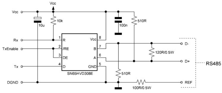
                            The 510 ohm pull up and pull down resistors are usually mounted on the master side. Theoretically it
                            would be best to install it in the middle of your bus line. The 120 ohm termination resistor must always
                            be used on distances greater than 1 meter and/or baud rates higher than 9600. It’s best to install it as a
                            norm as noise and reflections will cause havoc on your communication once implemented in the field.
                            The termination resistors should be mounted at both ends of the bus line. Please note that adding bias
                            resistors will load the driver IC output. With the indicated values the max number of units on the bus
                            line is limited to eight 12kΩ, sixteen 24kΩ, or thirty-two 48kΩ units.
                            For further protection transient suppressors can be installed across the differential lines, from the Vcc to
                            D+ and from GND to D-.!
                            0_1491314128147_upload-f4c63383-2b9a-4f3d-bd48-1e25fcf9dc76

                            MySensors 2.3.2; contr:Domoticz; layer: RS485, nRF24; gw: Ethernet, Serial

                            1 Reply Last reply
                            0
                            • A Offline
                              A Offline
                              ArduiSens
                              wrote on last edited by
                              #99

                              Google for simple Modbus Master dcouments (arduino forum)

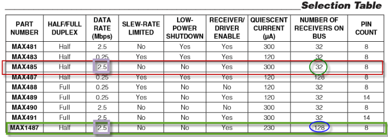
                              The MAX485 is not the best RS485 chip because of it's own internal impedance.
                              The chip in the diagram can be change by MAX485, MAX...
                              0_1491314500978_upload-db69c9ce-43b6-430d-8807-74438ad83b96

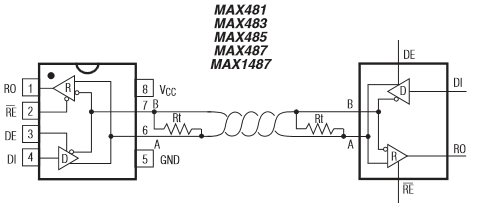
                              https://datasheets.maximintegrated.com/en/ds/MAX1487-MAX491.pdf

                              MySensors 2.3.2; contr:Domoticz; layer: RS485, nRF24; gw: Ethernet, Serial

                              1 Reply Last reply
                              0
                              • A Offline
                                A Offline
                                ArduiSens
                                wrote on last edited by
                                #100

                                FYI
                                0_1491315316611_upload-40d28ad1-8ba3-4a11-aa7b-5bd1e84424d2

                                MySensors 2.3.2; contr:Domoticz; layer: RS485, nRF24; gw: Ethernet, Serial

                                1 Reply Last reply
                                0
                                • nofoxN Offline
                                  nofoxN Offline
                                  nofox
                                  wrote on last edited by
                                  #101

                                  Hi, I'm building my home automation system and I have UTP cables cat5e in walls going to my wall switches. I have four cables, 5 nodes on one cable, 2 nodes on the second cable, and one node on 3rd and one 4th cable. 9 nodes. I know that the RS485 should be connected in parallel on single twisted pair but i cant change cables now cause my walls are painted etc.. So I have few problems, nodes stops working, i need to reset them few times, after few days the network stops to work and i start to search for an answers here. I changed numbers of SOH from 1 to 3 in 274 line of MyTransportRS485.cpp and now I think the network working better. I have 120ohm resistor in every node. You think that I should remove them ? Nodes are max 10 meters from the gateway so the cable lengths aren't so long.

                                  K 1 Reply Last reply
                                  0
                                  • nofoxN nofox

                                    Hi, I'm building my home automation system and I have UTP cables cat5e in walls going to my wall switches. I have four cables, 5 nodes on one cable, 2 nodes on the second cable, and one node on 3rd and one 4th cable. 9 nodes. I know that the RS485 should be connected in parallel on single twisted pair but i cant change cables now cause my walls are painted etc.. So I have few problems, nodes stops working, i need to reset them few times, after few days the network stops to work and i start to search for an answers here. I changed numbers of SOH from 1 to 3 in 274 line of MyTransportRS485.cpp and now I think the network working better. I have 120ohm resistor in every node. You think that I should remove them ? Nodes are max 10 meters from the gateway so the cable lengths aren't so long.

                                    K Offline
                                    K Offline
                                    kimot
                                    wrote on last edited by
                                    #102

                                    @nofox
                                    If you have got one free pair of wires in cat5e cable, it is easy to convert your "star" topology to pure 485 bus topology with terminal resistors on both ends only.

                                    nofoxN 1 Reply Last reply
                                    0
                                    • gohanG Offline
                                      gohanG Offline
                                      gohan
                                      Mod
                                      wrote on last edited by
                                      #103

                                      I think the 120Ohms resistor needs to go at the end of the cable, not on each node

                                      1 Reply Last reply
                                      0
                                      • K kimot

                                        @nofox
                                        If you have got one free pair of wires in cat5e cable, it is easy to convert your "star" topology to pure 485 bus topology with terminal resistors on both ends only.

                                        nofoxN Offline
                                        nofoxN Offline
                                        nofox
                                        wrote on last edited by
                                        #104

                                        @kimot I was thinking about that before I wrote here, and if nothing else can help I will convert star to bus.

                                        1 Reply Last reply
                                        0
                                        • A Offline
                                          A Offline
                                          ArduiSens
                                          wrote on last edited by
                                          #105

                                          @nofox it's what gohan stated, the 120ohm resistors should only put on the first and last node of you network. And you can only use a "bus" network topology for RS485.You should use the other wires of you Ethernet cable to accomplish this like kimot wrote.

                                          MySensors 2.3.2; contr:Domoticz; layer: RS485, nRF24; gw: Ethernet, Serial

                                          1 Reply Last reply
                                          0
                                          Reply
                                          • Reply as topic
                                          Log in to reply
                                          • Oldest to Newest
                                          • Newest to Oldest
                                          • Most Votes


                                          3

                                          Online

                                          11.7k

                                          Users

                                          11.2k

                                          Topics

                                          113.0k

                                          Posts


                                          Copyright 2019 TBD   |   Forum Guidelines   |   Privacy Policy   |   Terms of Service
                                          • Login

                                          • Don't have an account? Register

                                          • Login or register to search.
                                          • First post
                                            Last post
                                          0
                                          • OpenHardware.io
                                          • Categories
                                          • Recent
                                          • Tags
                                          • Popular