Current Sensing?
-
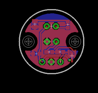
It took me less an hour for the box+pcb..i wouldn't have invest more time as i've lot of others stuff to do.
For the connector, I let the user choosing as I'm not really planning to design a dedicated pcb for the mcu side. Because there are already lot of boards and it just need one signal. Or I have multiple custom dev board with usb connection too etc. I was mainly interested in doing a low power sensor with a good digital level. Now I need to check my little idea..@scalz - Perfect, okay. Well i will sort something out with the MCU side in mine then. I might go down the route of custom board, but then again, it may be easier for the user to just use a arduino maybe, just that the connection of the sensor would be a little 'temp' if i don't do a custom board maybe. Not sure yet. Will get the sensor product sorted first.
-
@gohan The trouble is though, as i mentioned just in the post regarding the product from OpenEnergyMonitor, a photo transistor is not the best/optimal way to go about this. As the LM393 module is built, it is the correct method. Using a photodiode and a comparator. No one seems to be doing that, and this is exactly what i'm doing right now. I'm pretty confident we can get this to a size that would satisfy your suggestions, we shall see.
Edit: Typo.
-
assembled my sensor this noon.
It looks like this from the top view, with the indication led (optional if battery powered device). The sensor is of course on bottom.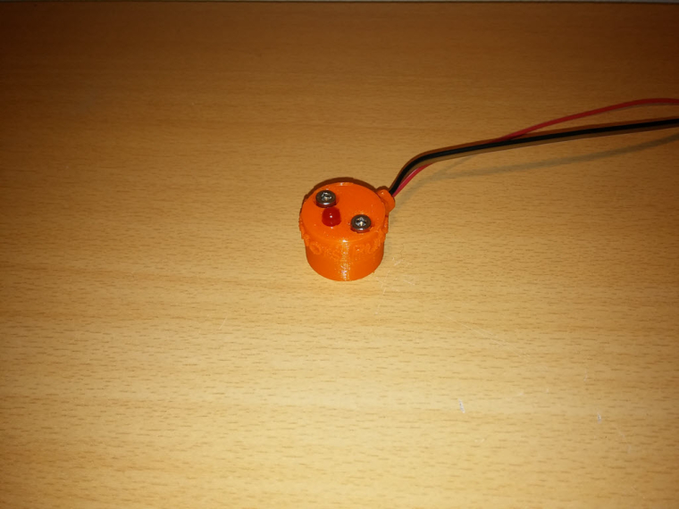
So i just ran a few tests and was able to detect up to 40hz. Then missed pulses started. but i've not tweaked it yet.
My test config was a signal generator connected to an external led, put it in front of my sensor. And checked the result with a scope.
I think 40Hz should be enough lol, and was very suprised i was able to go as high with my circuit, that's cool.I'll upload my files at openhardware
Enjoy MySensors Pulse :)
-
assembled my sensor this noon.
It looks like this from the top view, with the indication led (optional if battery powered device). The sensor is of course on bottom.So i just ran a few tests and was able to detect up to 40hz. Then missed pulses started. but i've not tweaked it yet.
My test config was a signal generator connected to an external led, put it in front of my sensor. And checked the result with a scope.
I think 40Hz should be enough lol, and was very suprised i was able to go as high with my circuit, that's cool.I'll upload my files at openhardware
Enjoy MySensors Pulse :)
-
@Samuel235
My bet is there isn't one :D -
@gohan - I'd be pretty shocked if there was when it was made this quick. Either way, its very nice and a quick turn around.
-
@Samuel235 do not underestimate the @scalz man!
-
thx guys :joy:
@Samuel235
in fact i'm jealous of you too as you're studying electronics, looks cool ;)
I've only designed the pcb for the moment, electronics in my thing is air wired, i don't remember how this soldering style is named??
so this looks like this
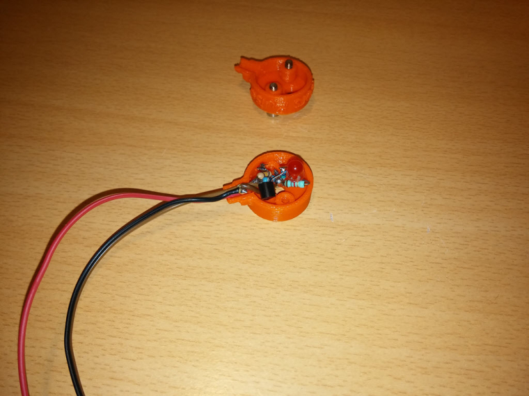
i'll check a few things for tomorrow, and also would like to try sensing a few others led colors and i'll post, no problem. I've been able to go up to 110hz though, then it was fluctuating too much (40hz was because i forgot to remove a capa on the signal generator side). -
@Samuel235
My bet is there isn't one :D@gohan said in Current Sensing?:
@Samuel235
My bet is there isn't one :D@Samuel235 said in Current Sensing?:
@gohan - I'd be pretty shocked if there was when it was made this quick. Either way, its very nice and a quick turn around.
rooo i didn't pay attention! So who pay for the bet :joy: but that's gohan which is betting, right :stuck_out_tongue:
So there is one, which should be very low power, afew uA (compared to the 0.4mA min of the lm393), and cheap. I just need to change a few routes, very quick.I told you ;) (i'm kidding of course)
-
@gohan said in Current Sensing?:
@Samuel235
My bet is there isn't one :D@Samuel235 said in Current Sensing?:
@gohan - I'd be pretty shocked if there was when it was made this quick. Either way, its very nice and a quick turn around.
rooo i didn't pay attention! So who pay for the bet :joy: but that's gohan which is betting, right :stuck_out_tongue:
So there is one, which should be very low power, afew uA (compared to the 0.4mA min of the lm393), and cheap. I just need to change a few routes, very quick.I told you ;) (i'm kidding of course)
-
ahah, well played ;)
-
No, you owe us all money! STAND BY YOUR BET! xD
I like it @scalz - you're approach is much better for low power modes, much better than mine. I see that the comparator is not needed for such application, i'm going that route because its the 'done' way. However, you're style is much better for battery powered nodes which will naturally attract people.
I'm really struggling to get to grips with KiCAD and i'm starting to give up after just one footprint. This thing would have been hours ago if i just used eagle.
The style is more 'inline' (not the technical term, but that is how i know it). What photodiode/resistor are you using? Most should pick up quite a decent range of wavelengths on the blinking LED.
-
thx guys :joy:
@Samuel235
in fact i'm jealous of you too as you're studying electronics, looks cool ;)
I've only designed the pcb for the moment, electronics in my thing is air wired, i don't remember how this soldering style is named??
so this looks like this
i'll check a few things for tomorrow, and also would like to try sensing a few others led colors and i'll post, no problem. I've been able to go up to 110hz though, then it was fluctuating too much (40hz was because i forgot to remove a capa on the signal generator side).@scalz - The general photodiode has a range of "Wavelength range (S10%) 400 nm to 1100 nm (SFH
213)", quoted from a datasheet here: http://www.osram-os.com/Graphics/XPic5/00101689_0.pdf. So this means that we should be good for a fair few different LED colours. -
@scalz - I wouldn't be jealous of me, my school is pretty bad to be honest with you. But it gets me a degree! I'm actually working/studying in the robotics field, so not just electronics :) We have a PCB router at school and I'm trying to get permission to use this for our projects here too, only for prototyping ofc. Finished boards will be ordered from a board house for a more professional feel, but it allows me to get an idea of the size of board we can get our designs down too and such.
I've also given up with KiCAD for now, it feels so unprofessional to get libraries and such made. Individual addons/programs inside of KiCAD to do different aspects just feels so clunky to me right now, eagle has my attention until i get my hands on solidworks PCB.
-
Here are the renders for my enclosure, will be printing in the morning and will report back with some more progress photos.
I did try to get the font into the same font as we use for the official logos of MySensors but the font really didn't correspond with solidworks, there are missing faces and lines all over the generated font and therefor it wasn't an option. If anyone knows a work around or something i could do to make it look remotely like the logo then please inform me. At some point i may attempt to put our little man logo on there instead of the opensource hardware logo, maybe.
I have designed the cable inlet with ethernet cable in mind, that may change too, not sure yet. I'm going for the cheap and locking/latching RJ45 rather than something that could slip out of socket as most of us use our electric cupboards for other uses as well such as cloakrooms for coats and such in the UK.
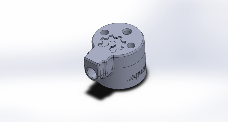

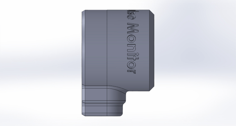
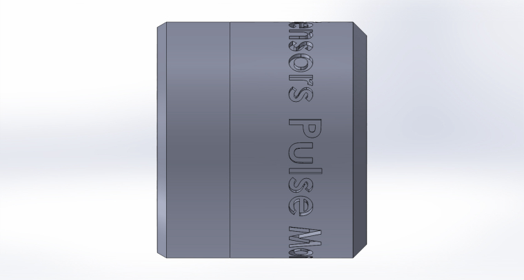
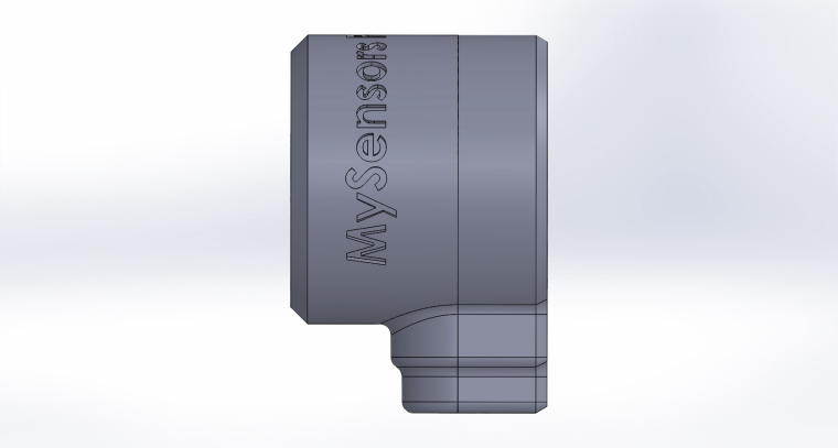
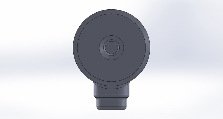
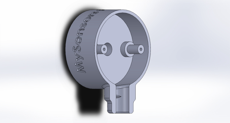
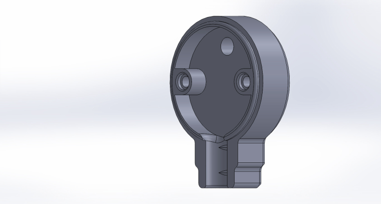
Would anyone like to see anything on here that i haven't thought about? I'm open to criticism.
-
cool
regarding your print, i think it's better to extrude the text, i'm not sure you'll get a good rendering like this..
same thing for the logo.. i guess you'll print it facing to the bed, maybe that won't look so great too. -
cool
regarding your print, i think it's better to extrude the text, i'm not sure you'll get a good rendering like this..
same thing for the logo.. i guess you'll print it facing to the bed, maybe that won't look so great too.@scalz - I'm not keen on the extruded text look tbh, i'm testing this format but my printer is pretty good with overhangs and thats why i'm taking my chance on the logo on top. It will be facing the bed and so we shall see how it turns out. Its not the end of the world if it doesn't look pretty straight away but i'm hoping its acceptable :)
-
i know for the extruded text, me too though. but i think it's more in general, 3d printing, it is more readable. but you can try, sure it won't take so much time and maybe that'll work, can't wait to see how it looks now ;)
-
i know for the extruded text, me too though. but i think it's more in general, 3d printing, it is more readable. but you can try, sure it won't take so much time and maybe that'll work, can't wait to see how it looks now ;)
Hello! It looks like you're interested in this conversation, but you don't have an account yet.
Getting fed up of having to scroll through the same posts each visit? When you register for an account, you'll always come back to exactly where you were before, and choose to be notified of new replies (either via email, or push notification). You'll also be able to save bookmarks and upvote posts to show your appreciation to other community members.
With your input, this post could be even better 💗
Register Login