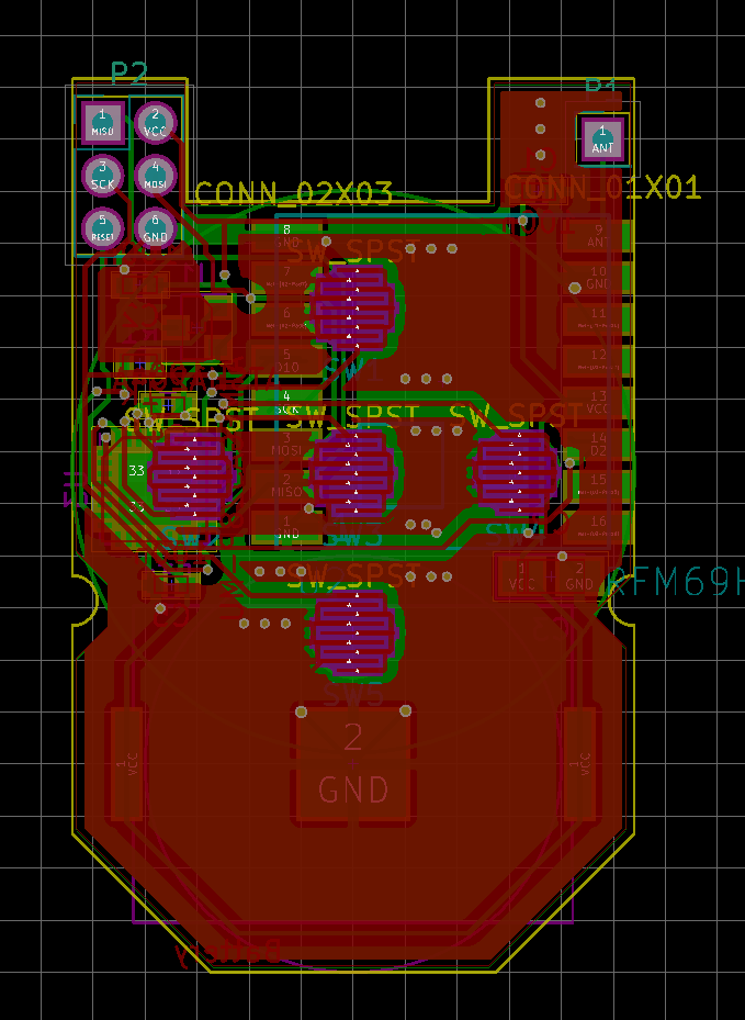
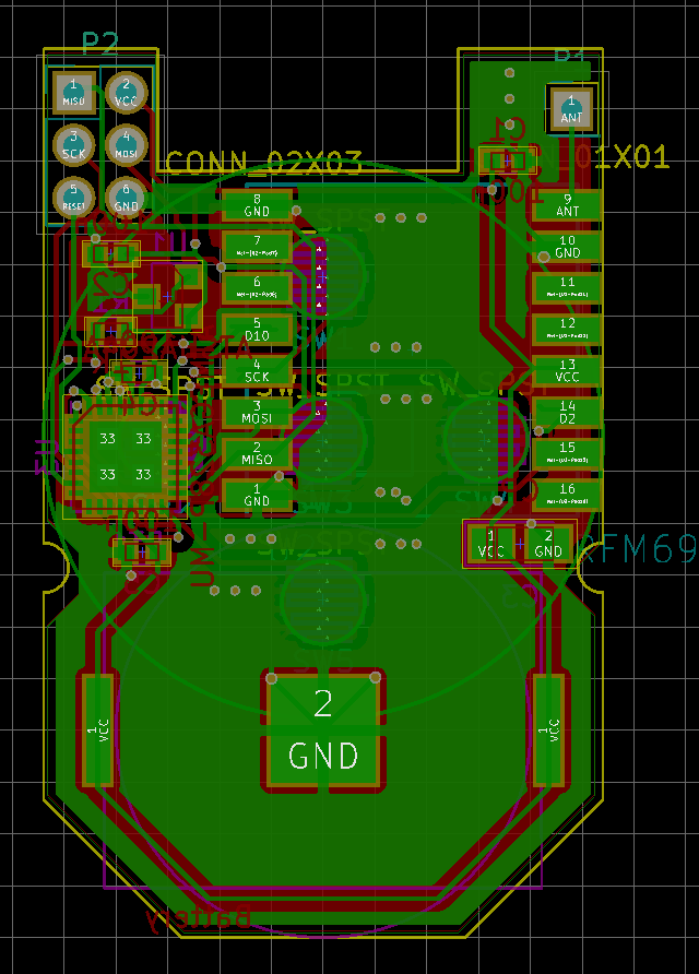
Secure 5-button keyfob with enclosure (was: 8-button keyfob)
-
@MiKa Thanks, lets hope so. Did one of you have a close look for issues, at least on the schematic? It's actually my first (MySensors/Ultra low power/THAT small) project.
Anyway, Seeed just dropped the price for 10 10x10cm^2 PCBs to 5$ plus shipping, so there is not much to loose except for 3 weeks waiting. I'll report any success or failure. Until then, the design is to be considered untested.I'm a little afraid of the TQFP package :) Hope I can handle it with my rework station, don't have a toaster oven ...
-
Hi,
I ordered some pieces of PCB 3 days ago based on your repo in Github (before last finalization by You) lets see in 3 weeks :)
TQFP package need just little bit practise and it will be OK :)
Im excited about this project :)
Regards,
MiKa@MiKa said in Secure 5-button keyfob with enclosure (was: 8-button keyfob):
before last finalization by You)
You should be fine. The antenna might need a little bending at the base, because the cutout didn't fit perfectly, but it is just a matter of <<1mm. The other changes, as far as I remember, were a purely cosmetic shift of the RGB LED and a little modification to keep the clearings for the v-cuts for the panelization.
If you have issues, I could send you a PCB for shipping costs. With the panelization, I'll have more PCBs than I ever could use. -
Since I wanted to get a gateway into the same shipment and only found the shield type gateway for the Wemos D1 Mini, which I didn't like, I quickly clicked together a PCB for that, supporting the RFM69HW (with 50Ohm impedance trace to an SMA connector), the through-hole NRF24L01 module and the SMD version with the ceramic antenna. (And of course an ATSHA204A.)
It can be powered over the D1 Mini or alternatively with up to 24V over a switching regulator.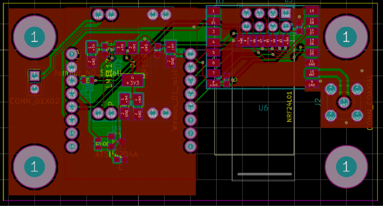
I guess there are dozens of those things around, so I won't spam another topic (as long as nobody disagrees), but I'll put it here for completeness.
https://github.com/kvoit/MySensors_SecureD1MiniGateway -
Hi,
I ordered some pieces of PCB 3 days ago based on your repo in Github (before last finalization by You) lets see in 3 weeks :)
TQFP package need just little bit practise and it will be OK :)
Im excited about this project :)
Regards,
MiKa@MiKa Hi, have you already received your PCBs? Mine came friday. on The bright side: Mechanically, everything fits fine into the keyfob enclosure. Nothing shakes, buttons fit accurately.
Unfortunately, I have more issues with the QFN package than I hoped. So I cannot tell anything electrically. Do you ahve it running? I am increasingly concerned that the coin cell will not be able to provide the necessary voltage and current spikes for a reasonably long time ... -
Hi,
pcb received today, ATmega is in place and running :) Currently just blink green and blue LED (red LED is connected to pin A7 and this can be just analog input and not output - what I understand from datasheet of ATMega328), I dont have slim RFM69 radio, but already ordered, test with radio is in plan for Wednesday :) -
Oh, A7, yeah, I remember something like that. Does the LED flash with the coin cell? The one I took from an RGB strip doesn't light up on blue at 3V because of the required forward voltage. I fear green might have the same fate when the battery voltage drops ...
Looks like V1.1 is required.Looking forward to hearing from the actual radio tests. Depending on that V1.1 might get some more caps or a HT7333 so it is possible to use a LIR2032.
-
Hi,
till now just tested from supply of USBasp programmer -3.3V, today I hope, I will have a time to play little bit with it :)
I already order couple of RFM95 for testing LoRa I hope RFM95 have the same footprint like RFM69HCW ;)
As a option for v1.1 is good to have some LDO in SOT23-5 package (SPX3819M5-L-3-3) with possibility to bypass - than You can use CR2032 and LIR2032 as well :thumbsup:
Next idea for v1.1 is to have RX,TX,DTR,GND and VCC pins somewhere on the edge of pcb for debugging and uploading sketch via bootloader and serial port
MiKa -
Hi,
till now just tested from supply of USBasp programmer -3.3V, today I hope, I will have a time to play little bit with it :)
I already order couple of RFM95 for testing LoRa I hope RFM95 have the same footprint like RFM69HCW ;)
As a option for v1.1 is good to have some LDO in SOT23-5 package (SPX3819M5-L-3-3) with possibility to bypass - than You can use CR2032 and LIR2032 as well :thumbsup:
Next idea for v1.1 is to have RX,TX,DTR,GND and VCC pins somewhere on the edge of pcb for debugging and uploading sketch via bootloader and serial port
MiKa@MiKa The SPX3819M5-L-3-3 has massive (well, comparably) quiescent current. Ten times the HT7333. That alone will suck a LIR2032 empty in about a month. I think I can fit the SOT-89 of the HT7333 package next to the LED. Alternatively, one could conider boosting with a MCP16252.
Serial flashing capabilities requires one more capacitor and resistor ... And the routing is also already pretty difficult. What is the avantage? As far as I can see, it is just another flashing device ...
I do intend, though, to add 2 pins rx/tx to the icsp header. How did you do that one, by the way? Does your version already have the bigger holes? In the most recent version, it is intended to take a machined female header. with that, it fits into the enclosure. I am still thinking about changing it over to SMD pads, which I would interface with pogo pins. -
Thanks, I'll change that.
BTW, I found another reason against adding a serial programming interface: To safe power, brownout detection should be disabled. If the battery runs low, erratic behavior may occur, which includes jumping to arbitrary addresses in flash. If a bootloader is still there, there is code to write to the flash, which might damage the programming. On the other hand, I highly doubt that a failing mcu will manage to go through the full process of sending an authenticated button pres, especially since high current RF tasks are involved.
So it is probably generally advisable to not have the Arduino bootloader on there. -
V 1.1 of pcb should have really bigger side pads for battery holder, I already destroyed one pcb pads when I put in coin battery, probably reason is overheating this small pads during soldering the battery holder :angry:
@MiKa I have made a big new push to the repository. Here are the changes from the commit:
- Doubled size of battery pads.
- Added HT7333 to allow for LIR2032 lithium coin cell (Bridge pads for CR2032).
- Changed A7 to A2 to make LED work.
- Added SMD contacts for TX and GND for debug output (interface with pogo pins).
(Getting TX out was hard enough, RX just wasn't worth it, I thing we really do not need to send anything to a keyfob :))
I would have liked to put a step-up converter on there, but I have not found a possibility for one that does not need an inductor that is too bit to fit on there.
-
@elcaron you will need at least TX from your board in order to personalize the atsha204a. Lest you personalize it before you solder it on the board. The personalizer can operate without TX.
@Anticimex Why? I thought there is SKIP_UART_CONFIRMATION. I have to set USER_KEY, but isn't that generated once for the whole network? I figure it doesn't have to be the keyfob node that does that ...
-
@Anticimex Why? I thought there is SKIP_UART_CONFIRMATION. I have to set USER_KEY, but isn't that generated once for the whole network? I figure it doesn't have to be the keyfob node that does that ...
-
Wow, good progress! :)
Finnaly I start up sketch, but with USBasp is not possible to upload firmware to atmega when the radio is connected :angry: I put temporary radio via pin socket and I need to remove radio during programming :open_mouth: , maybe RFM69HCW need to have connected RESET pin or some pull-up is missing.
From sleep mode Im able to wake up node just via SW5 wchich is conneted to pin D3 (INT1), Its possible to wake up from some sleep mode also via another pins (except D2 which is INT0)? -
@elcaron yes, but how would you obtain the atsha204a serial if you want to be able to whitelist your keyfob?
@Anticimex Ok, I see ...
Well, good that we have TX now :) If my current version works, I'll personalize the ATSHA outside of the board. It's really easy to solder with a hot air gun.
Hello! It looks like you're interested in this conversation, but you don't have an account yet.
Getting fed up of having to scroll through the same posts each visit? When you register for an account, you'll always come back to exactly where you were before, and choose to be notified of new replies (either via email, or push notification). You'll also be able to save bookmarks and upvote posts to show your appreciation to other community members.
With your input, this post could be even better 💗
Register Login