Cant even get my first node working...
-
Try swapping radios between the gateway and node just to make sure radio is not fried. It could be a wiring problem like said before or a power problem.
-
Any solution to this? I have the same problem atm. Tried 3 or 4 different nrf24l01+ but with the same failures. I'm suspecting it's related to my sketches or something. Can't wire that many radios wrong, and they are from different vendors. My gateway is an Uno running with an W5100 and latest MySensors dev. Seems to be connecting just fine to both my Vera and when I tried it in Domoticz. The GW debug shows no fails.
-
try with just some example sketches to see if the radios are correctly communicating. Did you put a capacitor on the radio module?
@gohan I made a serial gateway with an Nano+Nrf24L01+ and hooked it up to my computer. Just to bypass the possibility that my regular gateway have radio problems. But even with that simple setup I get "11 !TSM:INIT:TSP FAIL" from the Nano. I have tried with 4.7, 47 and 100uF on the radio.
-
-
Im banging my head against the wall here. Uninstalled IDE and reinstalled version 1.6.4 and added Mysensors lib from the menus. Uploaded the GatewaySerial to a new Uno with attached radio+cap. No luck.
Uninstalled IDE and installed latest version which has Mysensors preinstalled. Same sketch. No luck. Gonna try with yet another radio. But I cant see how the 3 i've already tried could be broken.
-
@gohan http://www.ebay.com/itm/400594940658?rmvSB=true
Its the radios linked in mysensors store...https://www.m.nu/breakout-boards/nrf24l01
"swedish" one. -
@gohan http://www.ebay.com/itm/400594940658?rmvSB=true
Its the radios linked in mysensors store...https://www.m.nu/breakout-boards/nrf24l01
"swedish" one. -
@gohan http://www.ebay.com/itm/400594940658?rmvSB=true
Its the radios linked in mysensors store...https://www.m.nu/breakout-boards/nrf24l01
"swedish" one.@royson84 - do yo have a multimeter and can comfirm there are power to the radio? If you are using the PCB you need to have atleast one jumper connected (as we spoke about - so I suspect that is ok). Could you post a picture of the complete setup?
I live pretty near you (1.5h) in worst case scenario ;)
-
@gohan http://www.ebay.com/itm/400594940658?rmvSB=true
Its the radios linked in mysensors store...https://www.m.nu/breakout-boards/nrf24l01
"swedish" one. -
@royson84 - do yo have a multimeter and can comfirm there are power to the radio? If you are using the PCB you need to have atleast one jumper connected (as we spoke about - so I suspect that is ok). Could you post a picture of the complete setup?
I live pretty near you (1.5h) in worst case scenario ;)
@sundberg84 I do have a multimeter, but haven't used it in ages so I'm not sure how to honestly. =D
On the PCB I made all the connections by soldering but I have put that aside for now. Figure I must find out what I'm doing wrong with the radios first. Now when I'm trying to make a new serial gateway I've done so both with some soldering and some duponts.
Today, as a bit of a last restore, I'm gonna remove my radio from the ethernet gateway, which doesn't give me any failures in debug, and try the same setup with that. If that doesn't work, well..hehe.. Stuff is gonna break :smile:
I really appreciate all your help and suggestions guys!!
-
@sundberg84 I do have a multimeter, but haven't used it in ages so I'm not sure how to honestly. =D
On the PCB I made all the connections by soldering but I have put that aside for now. Figure I must find out what I'm doing wrong with the radios first. Now when I'm trying to make a new serial gateway I've done so both with some soldering and some duponts.
Today, as a bit of a last restore, I'm gonna remove my radio from the ethernet gateway, which doesn't give me any failures in debug, and try the same setup with that. If that doesn't work, well..hehe.. Stuff is gonna break :smile:
I really appreciate all your help and suggestions guys!!
@royson84 - take out your mulitimeter and set it to DC (see here for symbol)
Put the black lead to gnd on the radio and the red on positive:
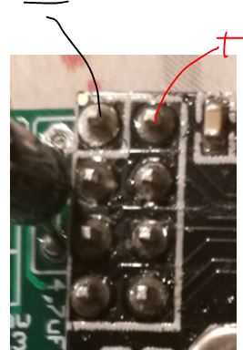
Also make sure the capacitors is aligned right!
If possible post a photo of the hole pcb :)
-
Ok, so it seems that I'm suffering from the ancient sickness of dumb-ass...
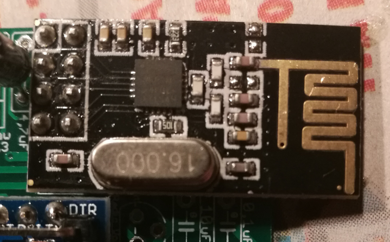
While connecting the radio from the gw, which has a little table on the back explaining all the pins, I realised that when connecting my other radios I forgot the mirror effect and therefore switched some of the connections :cry:
Now, when connected as they should, they work. Haha.
Also @sundberg84 i measured the voltage and on the PCB I only get about 0.03V on the radio but at the pro mini its 3.3 or thereabouts. Gonna have a look at the connections tonight.
About debugging the PCB. Do I have to remove the battery jumper when connecting the ftdi? Or do they not interfere if the battery's are off?
-
Ok, so it seems that I'm suffering from the ancient sickness of dumb-ass...
While connecting the radio from the gw, which has a little table on the back explaining all the pins, I realised that when connecting my other radios I forgot the mirror effect and therefore switched some of the connections :cry:
Now, when connected as they should, they work. Haha.
Also @sundberg84 i measured the voltage and on the PCB I only get about 0.03V on the radio but at the pro mini its 3.3 or thereabouts. Gonna have a look at the connections tonight.
About debugging the PCB. Do I have to remove the battery jumper when connecting the ftdi? Or do they not interfere if the battery's are off?
@royson84 - You can only have one power source so if you are using a battery make sure to disconnect one of them (normally i do not connect the voltage from the ftdi to make it as "real" as possible.) You might want to connect the ground to the ftdi though because otherwise you might get hard to read the serial output.
You should have the jumper connected at all times but if you power from the ftdi you change it to REG. Bat will feed the radio from the battery which is another circuit than the pro mini.
-
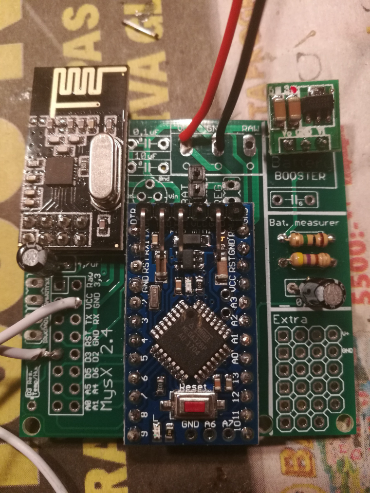
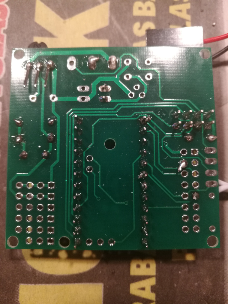
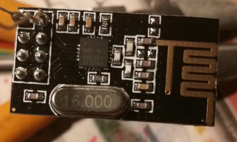
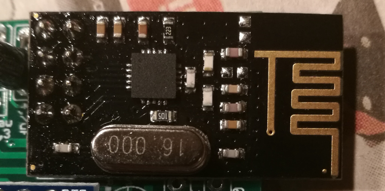
Heres pictures of one of the PCBs @sundberg84. Not sure why the power isnt reaching the radio in its full capacity. Have i not been careful enough with my soldering?
Hello! It looks like you're interested in this conversation, but you don't have an account yet.
Getting fed up of having to scroll through the same posts each visit? When you register for an account, you'll always come back to exactly where you were before, and choose to be notified of new replies (either via email, or push notification). You'll also be able to save bookmarks and upvote posts to show your appreciation to other community members.
With your input, this post could be even better 💗
Register Login