My Ethernet Gateway Board (W5500)
-
I also like the black box it comes in, very nicely done !
-
Hello everyone!
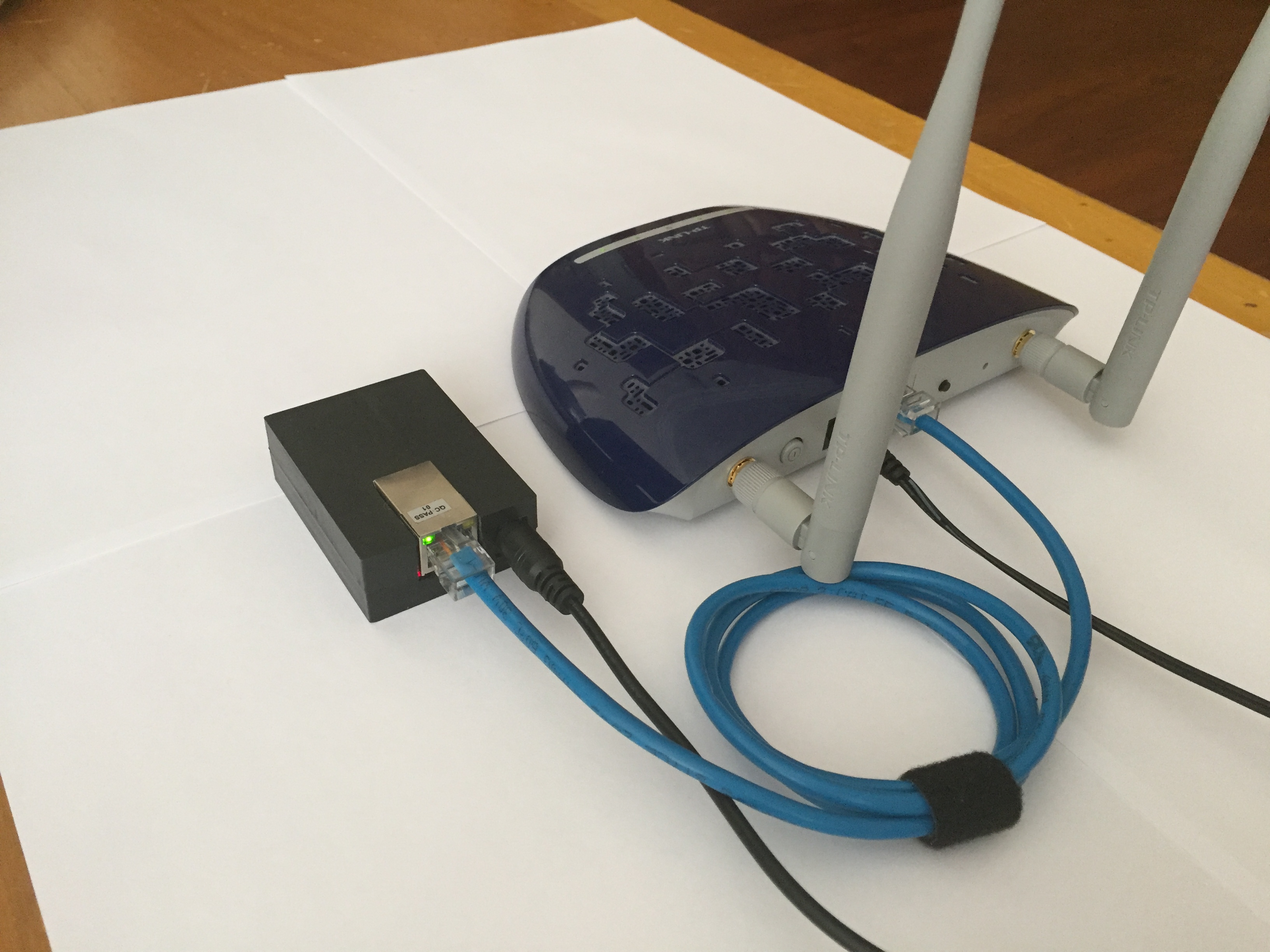
Just wanted to share my Ethernet Gateway build. It became pretty neat, I think.
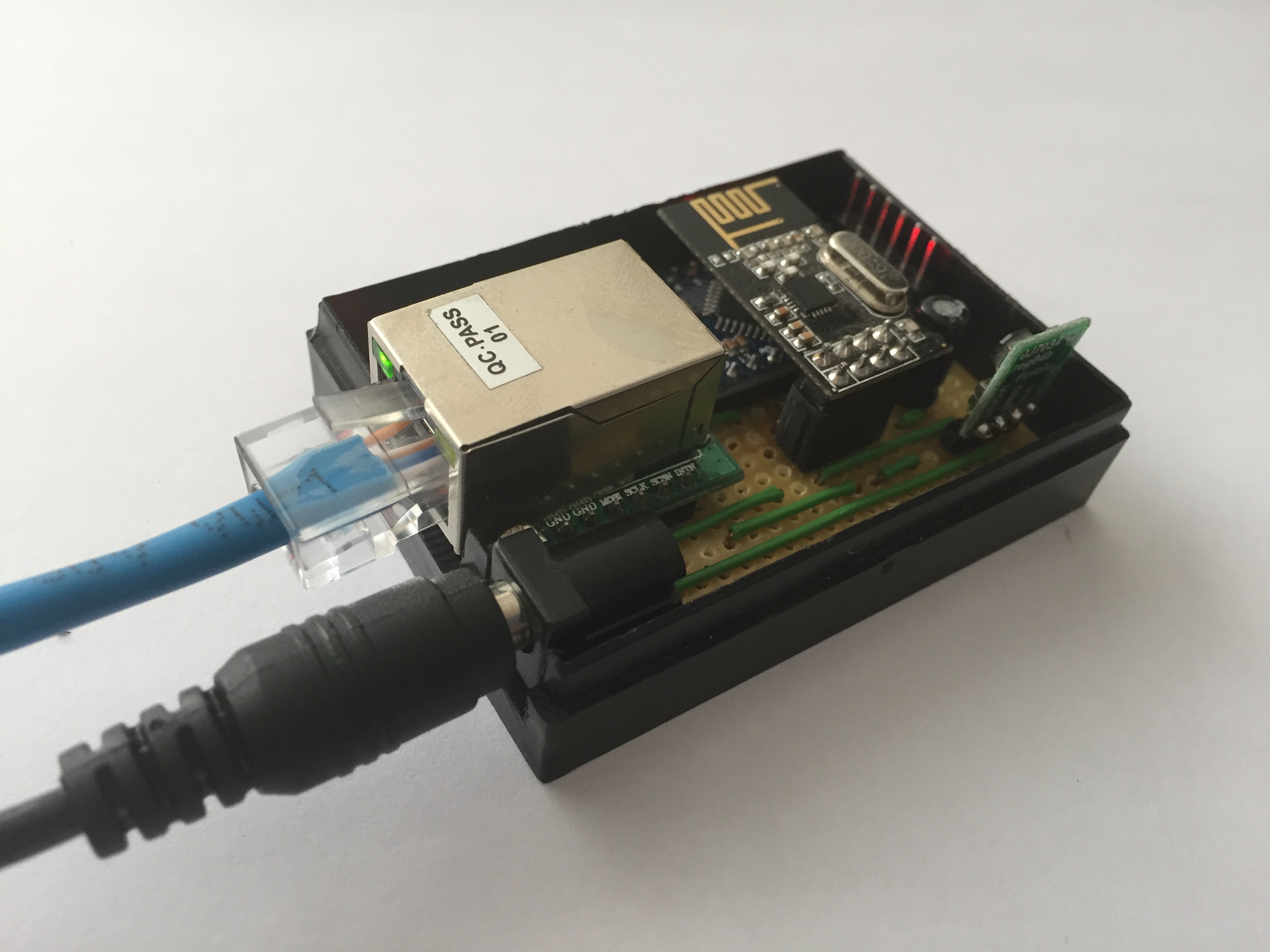
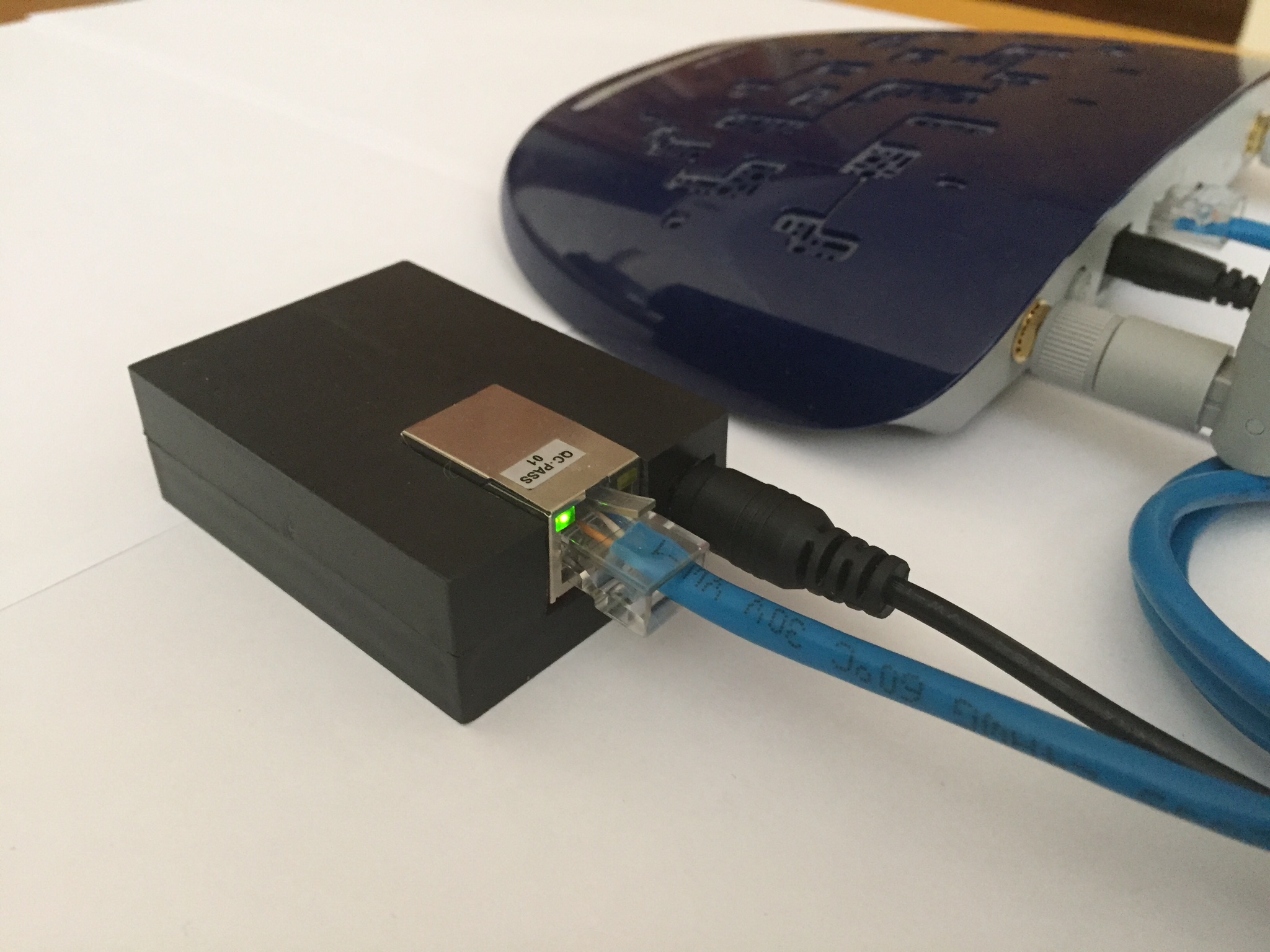
Connected to my WIFI extender.
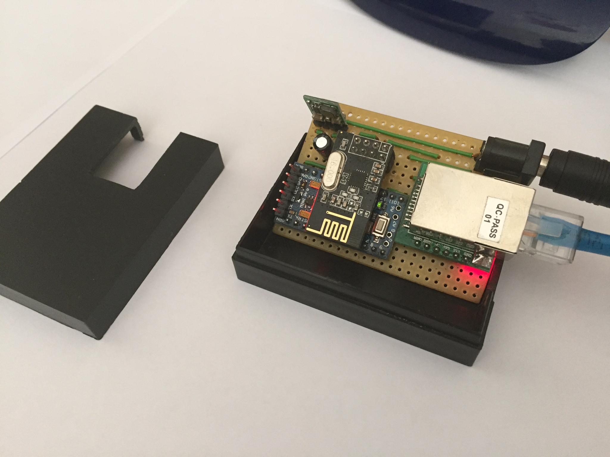
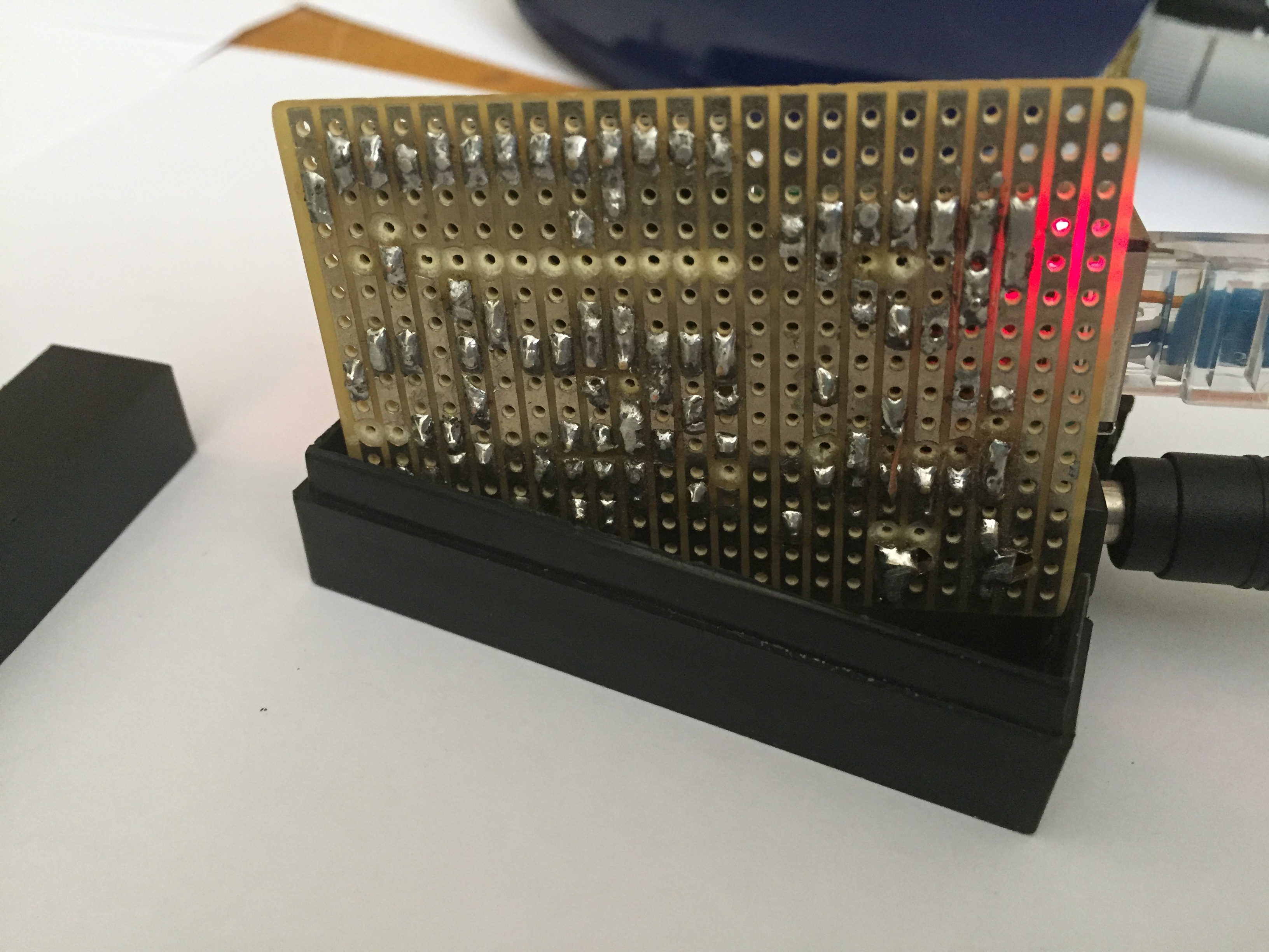
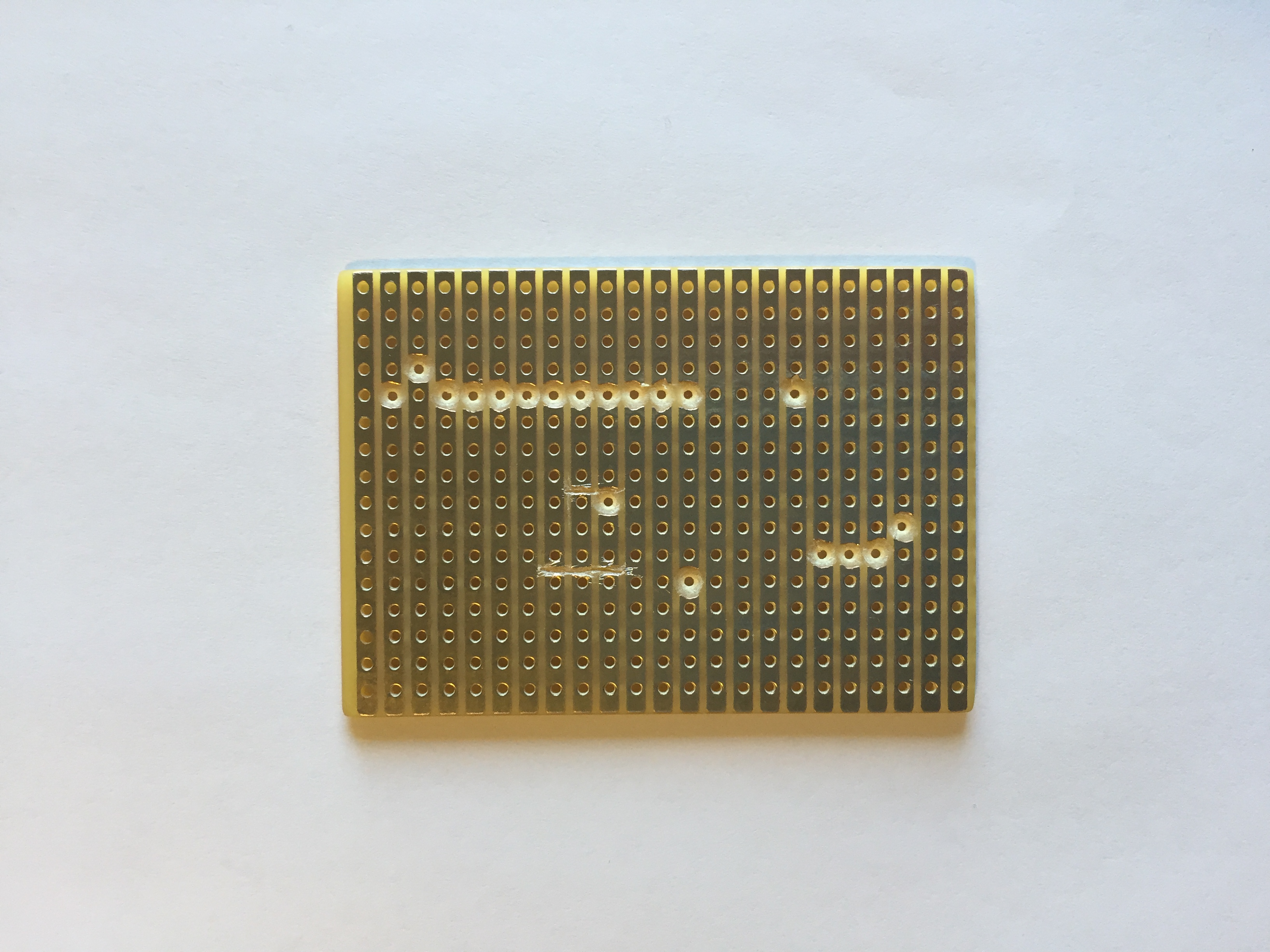
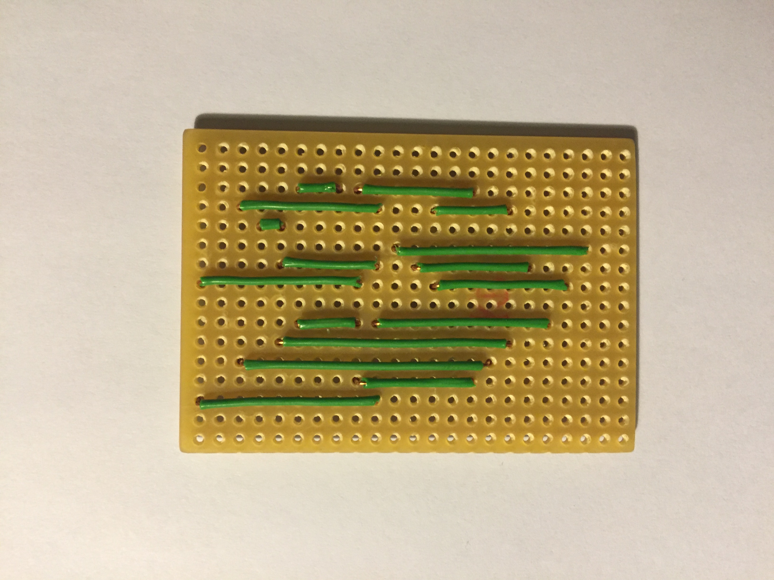
I'm using a Vero PCB Prototyping Board with copper strips. It makes it easier to solder and less cables.
To cut the copper strips on the Vero board I'm using a 5mm drill bit and my finger tips:

Example from a Vero Board Project:
You can buy them for example from here: Ebay
I'm using a W5500 Ethernet Module instead of W5100.
A W5500 Ethernet module is more compact, but a little bit more expensive.
If you'll use a W5500 Module as I do, you need to replace the Arduino Ethernet library first.
I'm using the following GitHub library from WizNet:
https://github.com/Wiznet/WIZ_Ethernet_Library
Use the Arduino IDE 1.5.X branch.
Replace everything in the original Ethernet Library (Ethernet\src\ directory). If you're using Windows they should be in following directory:
C:\Program Files (x86)\Arduino\libraries\Ethernet\src
In the file W5100.h located in \Ethernet\src\utility\ it's preset as a W5500 WizNet chip://#define W5100_ETHERNET_SHIELD // Arduino Ethenret Shield and Compatibles ... //#define W5200_ETHERNET_SHIELD // WIZ820io, W5200 Ethernet Shield #define W5500_ETHERNET_SHIELD // WIZ550io, ioShield series of WIZnetFor my Vero board design I made the drawing in Excel. It works pretty well for me. :smiley:
Have a look at my Excel file attached here:
0_1453581415262_MySensor Ethernet GW Circuit Board.xlsxI'm using an Arduino Pro Mini 3.3V 8MHz.
The Voltage Regulator used in this design (D24V3F3 3.3V) is from Pololu.
Please note that the internal Voltage Regulator in the Arduino Pro Mini isn't powerful enough to run the W5500 Ethernet Module.@jpaulin I see that you are using the W5500 chipset on your Ethernet module... According to the specs of the W5500 chip, it looks like it has a MAC address. Have you tried to get a DHCP address using the native MAC Address of the W5500?
I'm considering going with that USR-ES1 as well. I like the small form factor, but I won't waste my time if it doesn't already have a MAC address. Backup plan is the W550io, which supposedly has MAC address embedded. Same chipset.
Thanks!
Treborjm87
Rob
-
@jpaulin I see that you are using the W5500 chipset on your Ethernet module... According to the specs of the W5500 chip, it looks like it has a MAC address. Have you tried to get a DHCP address using the native MAC Address of the W5500?
I'm considering going with that USR-ES1 as well. I like the small form factor, but I won't waste my time if it doesn't already have a MAC address. Backup plan is the W550io, which supposedly has MAC address embedded. Same chipset.
Thanks!
Treborjm87
Rob
@treborjm87
I made some tests with the MAC address. As far as I can see there's no MAC address being generated from my W5500 module. With no pre-set MAC address sent the WiFi Router stops working with the gw (Ethernet.begin()). It does work with one of my older routers. My guess is the older router ignores the missing MAC address. -
@treborjm87
I made some tests with the MAC address. As far as I can see there's no MAC address being generated from my W5500 module. With no pre-set MAC address sent the WiFi Router stops working with the gw (Ethernet.begin()). It does work with one of my older routers. My guess is the older router ignores the missing MAC address.I am struggling to get the USR-ES1 to work. I am using IDE 1.6.11. (At this point, I am only trying to get the WebServer to work) It looks like all of the libraries are set up correctly, by default, i.e. the #define (#define W5500_ETHERNET_SHIELD) that you mention above is already uncommented. There must be something else that I am missing??? All that I see from the debug window is "server is at 0.0.0.0"
Any chance you would allow me to see your code for your gateway?
Thanks again!
Rob
-
Bravo!! that is a great looking gateway.
-
Hello everyone!
Just wanted to share my Ethernet Gateway build. It became pretty neat, I think.
Connected to my WIFI extender.
I'm using a Vero PCB Prototyping Board with copper strips. It makes it easier to solder and less cables.
To cut the copper strips on the Vero board I'm using a 5mm drill bit and my finger tips:
Example from a Vero Board Project:
You can buy them for example from here: Ebay
I'm using a W5500 Ethernet Module instead of W5100.
A W5500 Ethernet module is more compact, but a little bit more expensive.
If you'll use a W5500 Module as I do, you need to replace the Arduino Ethernet library first.
I'm using the following GitHub library from WizNet:
https://github.com/Wiznet/WIZ_Ethernet_Library
Use the Arduino IDE 1.5.X branch.
Replace everything in the original Ethernet Library (Ethernet\src\ directory). If you're using Windows they should be in following directory:
C:\Program Files (x86)\Arduino\libraries\Ethernet\src
In the file W5100.h located in \Ethernet\src\utility\ it's preset as a W5500 WizNet chip://#define W5100_ETHERNET_SHIELD // Arduino Ethenret Shield and Compatibles ... //#define W5200_ETHERNET_SHIELD // WIZ820io, W5200 Ethernet Shield #define W5500_ETHERNET_SHIELD // WIZ550io, ioShield series of WIZnetFor my Vero board design I made the drawing in Excel. It works pretty well for me. :smiley:
Have a look at my Excel file attached here:
0_1453581415262_MySensor Ethernet GW Circuit Board.xlsxI'm using an Arduino Pro Mini 3.3V 8MHz.
The Voltage Regulator used in this design (D24V3F3 3.3V) is from Pololu.
Please note that the internal Voltage Regulator in the Arduino Pro Mini isn't powerful enough to run the W5500 Ethernet Module. -
@mtiutiu
I'm using MY_SOFTSPI to separate the SPI ports. I've never tried to share the SPI-bus with an NRF24 radio and W5500.I've seen Adafruit has released a library named "Ethernet2.h" for the W5500 module. It's a nice alternative, no need to replace the library when switching between a W5100 and W5500 Ethernet module. Haven't tested it, though.
For an RFM69 gateway that I've built with a W5500 Ethernet module I'm sharing the SPI bus. No SOFTSPI setup is available yet for the RFM69, as far as I know. In the following thread you can see my setup sharing the SPI port between an RFM69 radio and W5500 Ethernet module.
I saw a major transport rework was released Mar 28 in the development branch with a lot of new stuff. Maybe some solution has been included to share the SPI port Out of the Box? -
I am struggling to get the USR-ES1 to work. I am using IDE 1.6.11. (At this point, I am only trying to get the WebServer to work) It looks like all of the libraries are set up correctly, by default, i.e. the #define (#define W5500_ETHERNET_SHIELD) that you mention above is already uncommented. There must be something else that I am missing??? All that I see from the debug window is "server is at 0.0.0.0"
Any chance you would allow me to see your code for your gateway?
Thanks again!
Rob
@treborjm87
Sorry. I missed your chat.
Here's the code. I'm using the standard W5100 example with mqtt./** * The MySensors Arduino library handles the wireless radio link and protocol * between your home built sensors/actuators and HA controller of choice. * The sensors forms a self healing radio network with optional repeaters. Each * repeater and gateway builds a routing tables in EEPROM which keeps track of the * network topology allowing messages to be routed to nodes. * * Created by Henrik Ekblad <henrik.ekblad@mysensors.org> * Copyright (C) 2013-2015 Sensnology AB * Full contributor list: https://github.com/mysensors/Arduino/graphs/contributors * * Documentation: http://www.mysensors.org * Support Forum: http://forum.mysensors.org * * This program is free software; you can redistribute it and/or * modify it under the terms of the GNU General Public License * version 2 as published by the Free Software Foundation. * ******************************* * * REVISION HISTORY * Version 1.0 - Henrik Ekblad * * DESCRIPTION * The W5100 MQTT gateway sends radio network (or locally attached sensors) data to your MQTT broker. * The node also listens to MY_MQTT_TOPIC_PREFIX and sends out those messages to the radio network * * LED purposes: * - To use the feature, uncomment WITH_LEDS_BLINKING in MyConfig.h * - RX (green) - blink fast on radio message recieved. In inclusion mode will blink fast only on presentation recieved * - TX (yellow) - blink fast on radio message transmitted. In inclusion mode will blink slowly * - ERR (red) - fast blink on error during transmission error or recieve crc error * * See http://www.mysensors.org/build/esp8266_gateway for wiring instructions. * nRF24L01+ ESP8266 * VCC VCC * CE GPIO4 * CSN/CS GPIO15 * SCK GPIO14 * MISO GPIO12 * MOSI GPIO13 * * Not all ESP8266 modules have all pins available on their external interface. * This code has been tested on an ESP-12 module. * The ESP8266 requires a certain pin configuration to download code, and another one to run code: * - Connect REST (reset) via 10K pullup resistor to VCC, and via switch to GND ('reset switch') * - Connect GPIO15 via 10K pulldown resistor to GND * - Connect CH_PD via 10K resistor to VCC * - Connect GPIO2 via 10K resistor to VCC * - Connect GPIO0 via 10K resistor to VCC, and via switch to GND ('bootload switch') * * Inclusion mode button: * - Connect GPIO5 via switch to GND ('inclusion switch') * * Hardware SHA204 signing is currently not supported! * * Make sure to fill in your ssid and WiFi password below for ssid & pass. */ // Enable debug prints to serial monitor #define MY_DEBUG // Enables and select radio type (if attached) #define MY_RADIO_NRF24 //#define MY_RADIO_RFM69 #define MY_GATEWAY_MQTT_CLIENT // Set this node's subscribe and publish topic prefix #define MY_MQTT_PUBLISH_TOPIC_PREFIX "mygateway1-out" #define MY_MQTT_SUBSCRIBE_TOPIC_PREFIX "mygateway1-in" // Set MQTT client id #define MY_MQTT_CLIENT_ID "mysensors-1" // W5100 Ethernet module SPI enable (optional if using a shield/module that manages SPI_EN signal) //#define MY_W5100_SPI_EN 4 // Enable Soft SPI for NRF radio (note different radio wiring is required) // The W5100 ethernet module seems to have a hard time co-operate with // radio on the same spi bus. #if !defined(MY_W5100_SPI_EN) && !defined(ARDUINO_ARCH_SAMD) #define MY_SOFTSPI #define MY_SOFT_SPI_SCK_PIN 14 #define MY_SOFT_SPI_MISO_PIN 16 #define MY_SOFT_SPI_MOSI_PIN 15 #endif // When W5100 is connected we have to move CE/CSN pins for NRF radio #ifndef MY_RF24_CE_PIN #define MY_RF24_CE_PIN 5 #endif #ifndef MY_RF24_CS_PIN #define MY_RF24_CS_PIN 6 #endif // Enable these if your MQTT broker requires usenrame/password //#define MY_MQTT_USER "username" //#define MY_MQTT_PASSWORD "password" // Enable MY_IP_ADDRESS here if you want a static ip address (no DHCP) #define MY_IP_ADDRESS 192,168,1,72 // If using static ip you need to define Gateway and Subnet address as well #define MY_IP_GATEWAY_ADDRESS 192,168,1,1 #define MY_IP_SUBNET_ADDRESS 255,255,255,0 // MQTT broker ip address or url. Define one or the other. //#define MY_CONTROLLER_URL_ADDRESS "m20.cloudmqtt.com" #define MY_CONTROLLER_IP_ADDRESS 192, 168, 1, 70 // The MQTT broker port to to open #define MY_PORT 1883 /* // Enable inclusion mode #define MY_INCLUSION_MODE_FEATURE // Enable Inclusion mode button on gateway //#define MY_INCLUSION_BUTTON_FEATURE // Set inclusion mode duration (in seconds) #define MY_INCLUSION_MODE_DURATION 60 // Digital pin used for inclusion mode button //#define MY_INCLUSION_MODE_BUTTON_PIN 3 // Set blinking period #define MY_DEFAULT_LED_BLINK_PERIOD 300 // Flash leds on rx/tx/err // Uncomment to override default HW configurations //#define MY_DEFAULT_ERR_LED_PIN 16 // Error led pin //#define MY_DEFAULT_RX_LED_PIN 16 // Receive led pin //#define MY_DEFAULT_TX_LED_PIN 16 // the PCB, on board LED */ #include <Ethernet.h> #include <MySensors.h> void setup() { } void presentation() { // Present locally attached sensors here } void loop() { // Send locally attached sensors data here } -
Thanks for posting the code!
I had to take a break from the home automation world for a bit. So, it was great timing that you posted. I'm building my MQTT gateway with the w5500. I'm not completely ready to try the rfm69 yet!!!
Thanks again!!!
Rob
-
Hello everyone!
Just wanted to share my Ethernet Gateway build. It became pretty neat, I think.
Connected to my WIFI extender.
I'm using a Vero PCB Prototyping Board with copper strips. It makes it easier to solder and less cables.
To cut the copper strips on the Vero board I'm using a 5mm drill bit and my finger tips:
Example from a Vero Board Project:
You can buy them for example from here: Ebay
I'm using a W5500 Ethernet Module instead of W5100.
A W5500 Ethernet module is more compact, but a little bit more expensive.
If you'll use a W5500 Module as I do, you need to replace the Arduino Ethernet library first.
I'm using the following GitHub library from WizNet:
https://github.com/Wiznet/WIZ_Ethernet_Library
Use the Arduino IDE 1.5.X branch.
Replace everything in the original Ethernet Library (Ethernet\src\ directory). If you're using Windows they should be in following directory:
C:\Program Files (x86)\Arduino\libraries\Ethernet\src
In the file W5100.h located in \Ethernet\src\utility\ it's preset as a W5500 WizNet chip://#define W5100_ETHERNET_SHIELD // Arduino Ethenret Shield and Compatibles ... //#define W5200_ETHERNET_SHIELD // WIZ820io, W5200 Ethernet Shield #define W5500_ETHERNET_SHIELD // WIZ550io, ioShield series of WIZnetFor my Vero board design I made the drawing in Excel. It works pretty well for me. :smiley:
Have a look at my Excel file attached here:
0_1453581415262_MySensor Ethernet GW Circuit Board.xlsxI'm using an Arduino Pro Mini 3.3V 8MHz.
The Voltage Regulator used in this design (D24V3F3 3.3V) is from Pololu.
Please note that the internal Voltage Regulator in the Arduino Pro Mini isn't powerful enough to run the W5500 Ethernet Module. -
@Ed1500
Appreciate your feedback!
Here's another of my GW I'm using today, with an RFM69 radio, and with an Anarduino as Arduino CPU. I have both GWs up and running for quite a while without issues. The RFM69 GW has a better RF range, hence my preferred gw for most of my sensors. If you need more details, pls let me know. -
@Ed1500
Appreciate your feedback!
Here's another of my GW I'm using today, with an RFM69 radio, and with an Anarduino as Arduino CPU. I have both GWs up and running for quite a while without issues. The RFM69 GW has a better RF range, hence my preferred gw for most of my sensors. If you need more details, pls let me know.@jpaulin Thanks, that is good to know. I have the RFM69 HW running with a W5100/Promini. W5100 module needed a bit of a hardware tweak for SPI, but works well. Now I probably would have opted for the 5500 as well.
I just use it to communicate between two properties at some 500 meter distance, most sensors I use are attached to ESP8266 :-)Seems like a rather long Antenna on yr module. What frequency are you on?
-
@jpaulin Thanks, that is good to know. I have the RFM69 HW running with a W5100/Promini. W5100 module needed a bit of a hardware tweak for SPI, but works well. Now I probably would have opted for the 5500 as well.
I just use it to communicate between two properties at some 500 meter distance, most sensors I use are attached to ESP8266 :-)Seems like a rather long Antenna on yr module. What frequency are you on?
-
Hi i have the W5500 with pins and board
this one
and Arduino Uno R3
anything i need to change?- i guess i don't need that 3.3 converter right?
- i did the change of \Ethernet\src flashed the board
- now i will connect the NRF24 just like you did ? same pins?
anything else I should change?
Hello! It looks like you're interested in this conversation, but you don't have an account yet.
Getting fed up of having to scroll through the same posts each visit? When you register for an account, you'll always come back to exactly where you were before, and choose to be notified of new replies (either via email, or push notification). You'll also be able to save bookmarks and upvote posts to show your appreciation to other community members.
With your input, this post could be even better 💗
Register Login