Trouble flashing Arduino Pro Mini with a sketch
-
The wiring is done correctly, I've even tried to change the cables a few times until now but nothing works. I have no usb cable - the adapter has an usb port on it :
http://www.aliexpress.com/item/FT232-FT232RL-high-quality-USB-to-TTL-module/1955253925.html
http://www.aliexpress.com/item/Pro-Mini-Module-Atmega328-5V-16M-For-Arduino-Compatible-With-Nano/1503533345.html -
As per the suggestion from this thread I've tried to flash my UNO with the FTDI adapter, but it failed with the same error. It works without issue with the USB connection from the UNO.
I remember for sure that the adapter used to work, and I'm thinking that I might have a fake FTDI adapter. Anyone know how I can try to reflash it so it will work ? -
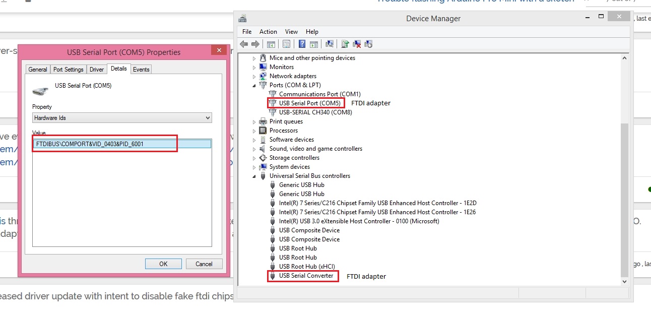
Well I don't think I have the exact same problem, only if they made another change to the driver - to display a fake ID after the chip was bricked ?
Here's what I see in Device Manager :
-
Well it must be the FTDI adapter, I went ahead and turned my UNO into a programmer, re-written the bootloader on the pro-mini, then flashed the sketch, and I'll test it after I make some re-touches to the dimmer board.
Actually I have a question if you can answer it, the sketch says the following :
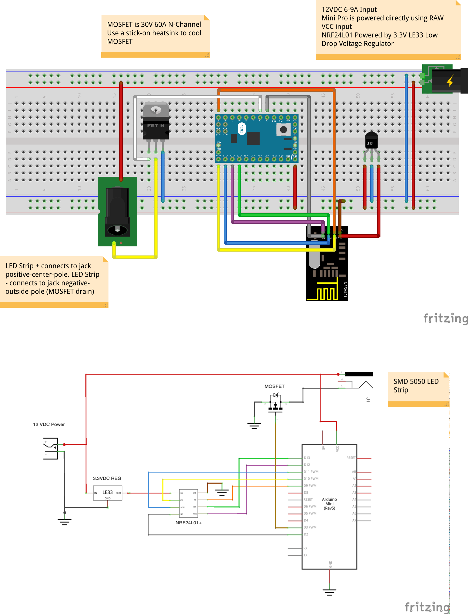
- The MOSFET Gate pin is connected to Arduino pin 3 (LED_PIN),
- The MOSFET Drain pin is connected to the LED negative terminal
- The MOSFET Source pin is connected to ground. -- is this the same as the Negative from the power supply or just GND pin from the Arduino. The schematic kind of confuses me.
LE: I think it's the - of the power supply :
-
Hard to tell in the breadboard. Make sure the V12 is going to the RAW pin and not the GND pin.
The breadboard also does not show a connection from the Arduino to GND. So add a connection from the Arduino GND pins to the minus terminal of the power supply. (This missing piece in the breadboard diagram is probably the source of the question)
GND and the minus terminal of the power supply should always be connected.
The FET is being used to control the current trough the LED to GND
As long as it's not running the current through the Arduino, it's fine.
Practically,- if you connect it to the Arduino GND ipin
- and the Arduino GND pin is connected to the minus terminal of the power supply
- Then the current is NOT going to go into the Arduino, it will go to the power supply's minus terminal (path of east resistance)
- So, anywhere there is a direct path to the minus terminal of the power supply is good.
Edward
@meanpenugin
Thanks so much for the explanation, and I'll try it once again as soon as I have some free time. For anyone looking for the original thread here is a link to it. -
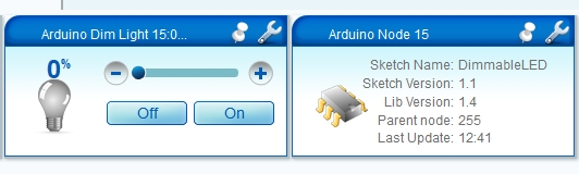
Thanks to @meanpenugin help I was able to finish with the soldering, but now I'm encountering trouble controlling the device.
For example I wasn't able to include it properly the first time, but after a few tries it was added on the dashboard and for some reason it has parent node 255 instead of GW ?
And when I try to control it I'm getting all sorts of errors :08 12/02/14 12:44:38.784 JobHandler_LuaUPnP::HandleActionRequest device: 40 service: urn:upnp-org:serviceId:Dimming1 action: SetLoadLevelTarget <0x2eca0680> 08 12/02/14 12:44:38.784 JobHandler_LuaUPnP::HandleActionRequest argument DeviceNum=40 <0x2eca0680> 08 12/02/14 12:44:38.785 JobHandler_LuaUPnP::HandleActionRequest argument serviceId=urn:upnp-org:serviceId:Dimming1 <0x2eca0680> 08 12/02/14 12:44:38.785 JobHandler_LuaUPnP::HandleActionRequest argument action=SetLoadLevelTarget <0x2eca0680> 08 12/02/14 12:44:38.785 JobHandler_LuaUPnP::HandleActionRequest argument newLoadlevelTarget=100 <0x2eca0680> 08 12/02/14 12:44:38.785 JobHandler_LuaUPnP::HandleActionRequest argument rand=0.12523629035042994 <0x2eca0680> 51 12/02/14 12:44:38.789 0x31 0x35 0x3b 0x30 0x3b 0x31 0x3b 0x31 0x3b 0x33 0x3b 0x31 0x30 0x30 0xd 0xa (15;0;1;1;3;100\r\n) <0x2af2a000> 52 12/02/14 12:44:38.856 0x30 0x3b 0x30 0x3b 0x33 0x3b 0x30 0x3b 0x39 0x3b 0x73 0x65 0x6e 0x64 0x3a 0x20 0x30 0x2d 0x30 0x2d 0x31 0x35 0x2d 0x31 0x35 0x20 0x73 0x3d 0x30 0x2c 0x63 0x3d 0x31 0x2c 0x74 0x3d 0x33 0x2c 0x70 0x74 0x3d 0x30 0x2c 0x6c 0x3d 0x33 0x2c 0x73 0x74 0x3d 0x66 0x61 0x69 0x6c 0x3a 0x31 0x30 0x30 (0;0;3;0;9;send: 0-0-15-15 s=0,c=1,t=3,pt=0,l=3,st=fail:100) <0x2e85d680> 08 12/02/14 12:44:46.039 JobHandler_LuaUPnP::HandleActionRequest device: 40 service: urn:upnp-org:serviceId:Dimming1 action: SetLoadLevelTarget <0x2eca0680> 08 12/02/14 12:44:46.039 JobHandler_LuaUPnP::HandleActionRequest argument DeviceNum=40 <0x2eca0680> 08 12/02/14 12:44:46.039 JobHandler_LuaUPnP::HandleActionRequest argument serviceId=urn:upnp-org:serviceId:Dimming1 <0x2eca0680> 08 12/02/14 12:44:46.039 JobHandler_LuaUPnP::HandleActionRequest argument action=SetLoadLevelTarget <0x2eca0680> 08 12/02/14 12:44:46.040 JobHandler_LuaUPnP::HandleActionRequest argument newLoadlevelTarget=0 <0x2eca0680> 08 12/02/14 12:44:46.040 JobHandler_LuaUPnP::HandleActionRequest argument rand=0.9738186305664368 <0x2eca0680> 51 12/02/14 12:44:46.048 0x31 0x35 0x3b 0x30 0x3b 0x31 0x3b 0x31 0x3b 0x33 0x3b 0x30 0xd 0xa (15;0;1;1;3;0\r\n) <0x2af2a000> 52 12/02/14 12:44:46.096 0x30 0x3b 0x30 0x3b 0x33 0x3b 0x30 0x3b 0x39 0x3b 0x73 0x65 0x6e 0x64 0x3a 0x20 0x30 0x2d 0x30 0x2d 0x31 0x35 0x2d 0x31 0x35 0x20 0x73 0x3d 0x30 0x2c 0x63 0x3d 0x31 0x2c 0x74 0x3d 0x33 0x2c 0x70 0x74 0x3d 0x30 0x2c 0x6c 0x3d 0x31 0x2c 0x73 0x74 0x3d 0x66 0x61 0x69 0x6c 0x3a 0x30 (0;0;3;0;9;send: 0-0-15-15 s=0,c=1,t=3,pt=0,l=1,st=fail:0) <0x2e85d680>Any way you can help me resolve this ?
Note that the voltage for the output is not adjusted when I try to control the level of the device.
One thing I've noticed is that after first powering the node the voltage drops consistently from ~9.5 V to about 0.01V in like 1 minute or so. And my arduino pro mini, powered by 12 V (~12.3V actually) is burning up really bad. I believe I might have a loop of some sort in my design ?Thanks.
-
Hi,
Did you check the voltage of the output of the power supply?
I bet it's over 12VLE33 seems to allow up to 20V
Arduino Mini Input Voltage range is 7-9 V
http://arduino.cc/en/Main/ArduinoBoardMiniI would check voltages at all the points to make sure it is in range.
Double check at the plugs (if you are using them) to make sure it's not shortedEdward
-
Yes, I did check the output it's 12.3 Volts and my chinese knockoff of the pro mini is rated to work with 12V. I'll try to get a regulator to power it at 5V instead and see how it goes. I don't use LE33, and went instead for the cheaper version the SOT23.
To power it to 5V I intend to use one of those USB adapters for the car's cigarette lighter, because I have a few lying around in my car. -
I'm running a similar setup for my RGBW led strip. Feeding my 5v Arduino Pro mini with 12V on the raw pin and powering the radio from VCC through a ams1117 3.3v regulator. Newer had any problems with it but I do recommend a high quality 12v source since the radio is sensitive to disturbance from the power source.
http://forum.micasaverde.com/index.php/topic,18103.msg157785.html#msg157785
I think you should check your wiring again, and again ;)
-
I apologize if you are aware of this, but are you pressing the reset button once the sketch is ready to transmit? Using a sparkfun FTDI board with knockoff pro minis, I press the reset button as soon as the first TX light blinks on serial board. If I don't: similar errors.
Hello! It looks like you're interested in this conversation, but you don't have an account yet.
Getting fed up of having to scroll through the same posts each visit? When you register for an account, you'll always come back to exactly where you were before, and choose to be notified of new replies (either via email, or push notification). You'll also be able to save bookmarks and upvote posts to show your appreciation to other community members.
With your input, this post could be even better 💗
Register Login