Skip to content
  • MySensors
  • OpenHardware.io
  • Categories
  • Recent
  • Tags
  • Popular
Skins
  • Light
  • Brite
  • Cerulean
  • Cosmo
  • Flatly
  • Journal
  • Litera
  • Lumen
  • Lux
  • Materia
  • Minty
  • Morph
  • Pulse
  • Sandstone
  • Simplex
  • Sketchy
  • Spacelab
  • United
  • Yeti
  • Zephyr
  • Dark
  • Cyborg
  • Darkly
  • Quartz
  • Slate
  • Solar
  • Superhero
  • Vapor

  • Default (No Skin)
  • No Skin
Collapse
Brand Logo
  1. Home
  2. Troubleshooting
  3. Standalone atmega328p and nrf24 not working.

Standalone atmega328p and nrf24 not working.

Scheduled Pinned Locked Moved Troubleshooting
11 Posts 4 Posters 3.4k Views 3 Watching
  • Oldest to Newest
  • Newest to Oldest
  • Most Votes
Reply
  • Reply as topic
Log in to reply
This topic has been deleted. Only users with topic management privileges can see it.
  • gohanG Offline
    gohanG Offline
    gohan
    Mod
    wrote on last edited by
    #2

    Are you running 8 mhz?

    1 Reply Last reply
    0
    • sundberg84S Offline
      sundberg84S Offline
      sundberg84
      Hardware Contributor
      wrote on last edited by sundberg84
      #3

      Please see https://forum.mysensors.org/topic/666/debug-faq-and-how-ask-for-help/ if you find anything there.

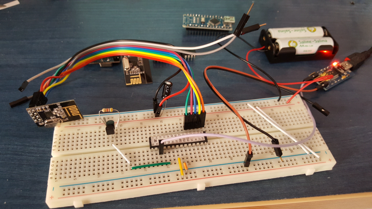
      Most likley you got the Radio not wired correctly.

      Controller: Proxmox VM - Home Assistant
      MySensors GW: Arduino Uno - W5100 Ethernet, Gw Shield Nrf24l01+ 2,4Ghz
      MySensors GW: Arduino Uno - Gw Shield RFM69, 433mhz
      RFLink GW - Arduino Mega + RFLink Shield, 433mhz

      1 Reply Last reply
      0
      • S scalpel

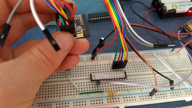
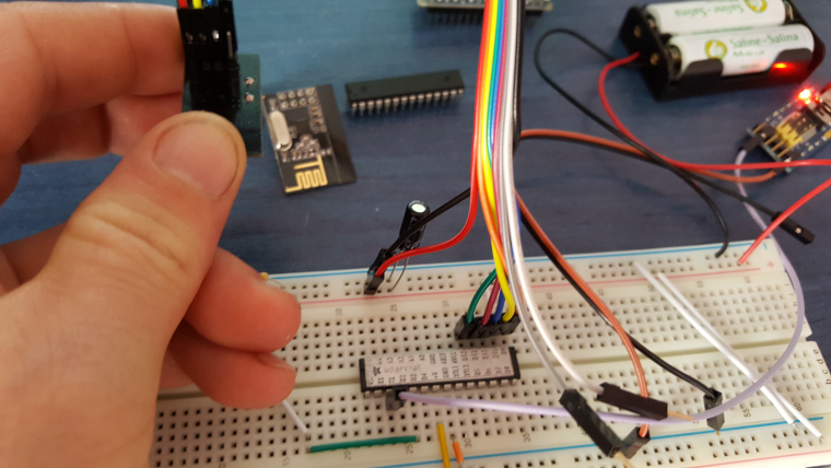
        Hi. Standalone atmega328p and nrf24l01 powered from two batteries AA. Votlage is 3,28V. Tried a lot of bootloaders and fuses, 3 other atmega and 3 other nrf still have same errors:

        10143 TSM:FAIL:RE-INIT
        10145 TSM:INIT
        10151 !TSM:INIT:TSP FAIL
        10156 TSM:FAIL:CNT=2
        10158 TSM:FAIL:PDT
        20162 TSM:FAIL:RE-INIT
        20164 TSM:INIT
        20170 !TSM:INIT:TSP FAIL
        20172 TSM:FAIL:CNT=3
        20176 TSM:FAIL:PDT
        

        Any ideas? Regards scalpel

        dbemowskD Offline
        dbemowskD Offline
        dbemowsk
        wrote on last edited by
        #4

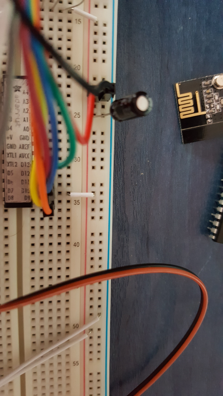
        @scalpel Do you have a decoupling capacitor on your radio's incoming power leads? If not, myself and a bunch of others are going to recommend that you put one on. It can be mounted right to the radio itself. It should be in the range of 4.7uf to 47uf. If you don't want the capacitor on top of the radio, mount it as close to the radio as you can.
        https://www.mysensors.org/build/connect_radio#connecting-a-decoupling-capacitor

        Vera Plus running UI7 with MySensors, Sonoffs and 1-Wire devices
        Visit my website for more Bits, Bytes and Ramblings from me: http://dan.bemowski.info/

        1 Reply Last reply
        0
        • S Offline
          S Offline
          scalpel
          wrote on last edited by
          #5

          Ive read a lot of topics and tried everything. Tried arduino 1.6 and arduino 1.8. Tried library 2.0 and 2.1.1. Added Capacitor 4,7uf. Tried 1mhz and 8mhz internal oscilator. Tried other sketches and still radio wont start.

          sundberg84S 1 Reply Last reply
          0
          • S scalpel

            Ive read a lot of topics and tried everything. Tried arduino 1.6 and arduino 1.8. Tried library 2.0 and 2.1.1. Added Capacitor 4,7uf. Tried 1mhz and 8mhz internal oscilator. Tried other sketches and still radio wont start.

            sundberg84S Offline
            sundberg84S Offline
            sundberg84
            Hardware Contributor
            wrote on last edited by
            #6

            @scalpel - if your radio wont start its either wrong wired, not enough power or hardware failure.

            Controller: Proxmox VM - Home Assistant
            MySensors GW: Arduino Uno - W5100 Ethernet, Gw Shield Nrf24l01+ 2,4Ghz
            MySensors GW: Arduino Uno - Gw Shield RFM69, 433mhz
            RFLink GW - Arduino Mega + RFLink Shield, 433mhz

            1 Reply Last reply
            0
            • gohanG Offline
              gohanG Offline
              gohan
              Mod
              wrote on last edited by
              #7

              Can you post a picture of the radio module? Did you try them on a normal arduino if they work?

              1 Reply Last reply
              0
              • S Offline
                S Offline
                scalpel
                wrote on last edited by
                #8

                0_1502791101343_20170815_115807.jpg
                0_1502791112425_20170815_115758.jpg
                0_1502791119338_20170815_115728.jpg

                sundberg84S 1 Reply Last reply
                0
                • gohanG Offline
                  gohanG Offline
                  gohan
                  Mod
                  wrote on last edited by
                  #9

                  The cap is a little far away from the radio but at least it should initialize. I see you have a nano in the background? If you attach the radio to that, does it still not work?

                  1 Reply Last reply
                  0
                  • S scalpel

                    0_1502791101343_20170815_115807.jpg
                    0_1502791112425_20170815_115758.jpg
                    0_1502791119338_20170815_115728.jpg

                    sundberg84S Offline
                    sundberg84S Offline
                    sundberg84
                    Hardware Contributor
                    wrote on last edited by sundberg84
                    #10

                    @scalpel IT also looks like you got a couple of capacitors missing on the atmega: http://www.gammon.com.au/breadboard.

                    Controller: Proxmox VM - Home Assistant
                    MySensors GW: Arduino Uno - W5100 Ethernet, Gw Shield Nrf24l01+ 2,4Ghz
                    MySensors GW: Arduino Uno - Gw Shield RFM69, 433mhz
                    RFLink GW - Arduino Mega + RFLink Shield, 433mhz

                    1 Reply Last reply
                    0
                    • S Offline
                      S Offline
                      scalpel
                      wrote on last edited by
                      #11

                      Awrgh! Sorry! Its working! There was small white jumper from previous project connected from VCC to CSN. Thank you for help.
                      0_1502792677410_20170815_121950.jpg

                      1 Reply Last reply
                      2
                      Reply
                      • Reply as topic
                      Log in to reply
                      • Oldest to Newest
                      • Newest to Oldest
                      • Most Votes


                      24

                      Online

                      11.7k

                      Users

                      11.2k

                      Topics

                      113.1k

                      Posts


                      Copyright 2025 TBD   |   Forum Guidelines   |   Privacy Policy   |   Terms of Service
                      • Login

                      • Don't have an account? Register

                      • Login or register to search.
                      • First post
                        Last post
                      0
                      • MySensors
                      • OpenHardware.io
                      • Categories
                      • Recent
                      • Tags
                      • Popular