Car Aux Battery Monitor
-
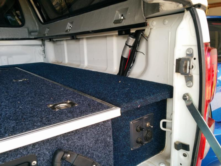
Ok fitted to the vehicle today. Tested the current draw and is around 9mA which is ok for this application.
The sketch remains the same although i have reduced the time between data sends to 30 min and will see how that goes.
I have used the roll from a plastic sandwich wrap box to hold the board. i just cut it to length and the board was a good fit.
I have used gaffer tape to seal the ends.
For the moment it is secured outside the battery area but will move it when the testing is complete
The switch on the bottom of the panel turns it off.
-
@Boots33 Nice application. Inspired me to have a look at the charge / discharge of my motorcycle battery. ;-)
@sincze Thanks for your comment. If this node works out ok I will see if I can build a low power version for my camper, I have ordered a couple of 3v pro mini's to tinker with. As @syotos has said a low power node will be best suited to the task.
I have now setup Domoticz to email me if the voltage exceeds or drops below my preset thresholds, will see how it performs during the week as it comes and goes from home.
-
What is the distance between your car and master gateway ? Do you use any repeater nodes ?
-
What is the distance between your car and master gateway ? Do you use any repeater nodes ?
@ahmedadelhosni My gateway is in a server cabinet in the garage so the node is within 7m of the gateway when the car is home. I do have areas of our block covered by repeater nodes but this node will usually connect directly to the gateway i would think.
If I build a unit for my camper it will have to go through a repeater to reach the gateway. -
You are my hero, man !!!
I have several 2xAA powered sensors that connect to a MySGateway without an UPS. Power outages are frequent in my street and when the power goes out on the gateway, the sensors eat their batteries trying to send data... Your method of checking the status of the uplink before trying to send is going to cost a little more during normal operations but will save a lot in case of outages.
Good idea!
-
You are my hero, man !!!
I have several 2xAA powered sensors that connect to a MySGateway without an UPS. Power outages are frequent in my street and when the power goes out on the gateway, the sensors eat their batteries trying to send data... Your method of checking the status of the uplink before trying to send is going to cost a little more during normal operations but will save a lot in case of outages.
Good idea!
@luizrrocha Great that you have found something of use in the code :) I have learnt a lot from others on this forum, the magic of open source! Let us know how you get on.
-
Well this has been running for the week now with the car coming and going. The node has to this point been performing as intended and is re-connecting without issues to the gateway when the car arrives home.
The only thing I have noticed is that the battery voltage is showing a bit lower than I was expecting. Nothing too drastic but I will need to check with a meter and see whether it is the node that needs adjustment or maybe my battery setup!
Still early days but I think that a low power version will be a great addition to my camper.
-
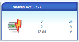
@Boots33 thanks for sharing, this project inspired me to have a monitor for my caravan battery :)
I have mine up and running now and did run in a small error present in your source code, on this line
present(ID_S_MULTIMETERV,V_VOLTAGE); // Register Sensor to gatewayThe present function should contain sensor type (S_xxxx values) and V_VOLTAGE is a payload message type.
So i think the presentation function should look like this.void presentation() { sendSketchInfo("Battery Sensor", "1.1"); // Send the sketch version information to the gateway and Controller present(ID_S_MULTIMETERV, S_MULTIMETER); // Register Sensor to gateway }Up and 'running':
-
@Boots33 thanks for sharing, this project inspired me to have a monitor for my caravan battery :)
I have mine up and running now and did run in a small error present in your source code, on this line
present(ID_S_MULTIMETERV,V_VOLTAGE); // Register Sensor to gatewayThe present function should contain sensor type (S_xxxx values) and V_VOLTAGE is a payload message type.
So i think the presentation function should look like this.void presentation() { sendSketchInfo("Battery Sensor", "1.1"); // Send the sketch version information to the gateway and Controller present(ID_S_MULTIMETERV, S_MULTIMETER); // Register Sensor to gateway }Up and 'running':
Thanks @BartE I don't know what I was thinking there!!!! I have made the change to the sketch. That's it no more drinking wine on a Sunday afternoon while working on a project. ;)
I think this node is a good example of how the I.O.T can be of practical use in a real world situation. Especially for items like vans and campers that can often spend months tucked away without use. To know the state of the battery is being monitored will mean one less thing for me to worry about.
Did you build a low power version, still waiting for my 3v pro mini to arrive so I can have a play. I will be keen to see how high I can go with the voltage divider resistors before it becomes unstable.
I know there have been a few posts on low power nodes before so will have to do a bit of digging through the old posts.I also put the multimeter on to check this node over the weekend and it is reading very close to the mark. So it seems I have a problem with the aux battery system! I will have to check a little further to see what is going wrong. Hope it is not the battery, they are not cheap to replace. Good that the problem has come to light though, better than being caught out.
-
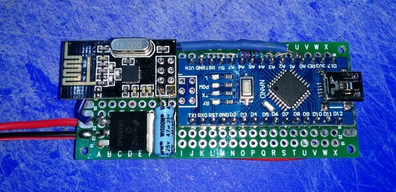
I have built a low power version today based on a 3v pro mini board and am so far very happy with the results.
On the pro mini the power LED needs to be disabled and the onboard regulator has to be removed. I followed the instructions on this page
To keep power draw down I have used much higher resistors for the voltage divider and have also included a capacitor to help keep it stable. In testing on the bench it has been very stable.
I have used an easy/newbie board from @sundberg84 which really did make the whole thing very easy :) It even already has the voltage divider layout taken care of. Thank you very much!!
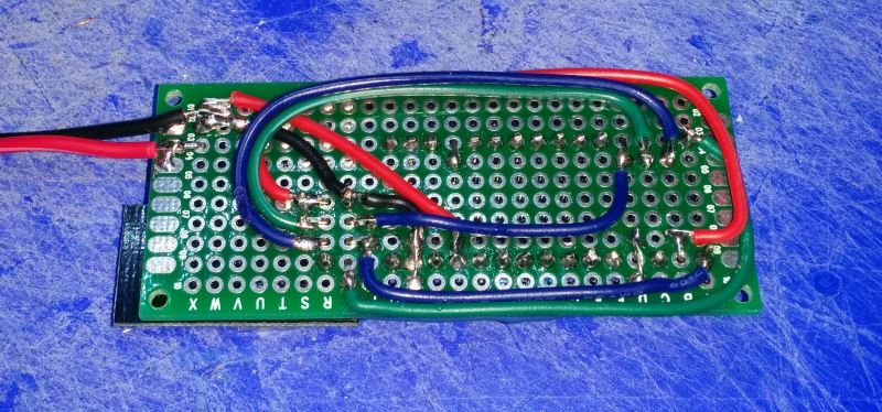
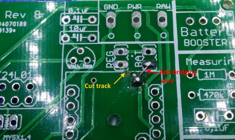
I had to make two minor mods to the board to accommodate the modified pro mini as shown below. Please note these changes are for Rev8 boards so different changes may be needed for other revisions. Rev9 definitely has had changes made to the power area.
The original version from my first post draws around 9ma when sleeping which is ok for my daily drive vehicle. This lower power version is way better for my camper. In testing on the bench these are the typical current requirements.
Booting up .......... 19ma Pretty high but this is only for a few seconds
Powered up and awake....... 4.8ma That's nearly half of the original when it was sleeping
powered up and sleeping ...... 90ua Bingo, this puppy should go for a while on my 200ah batteries ;)So the original draws 0.009A and this new version a miserly 0.00009A a very good result for long term monitoring.
I have modified the Sketch to suit the new node, the main change has been to add 10 reads and average the results to help keep it all stable.
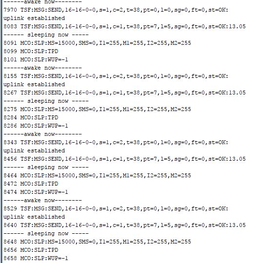
You can see from the serial data the node wakes, takes the reading, sends the data and is back to sleep in less than a blink of the eye! (this was only sleeping for 15 seconds during testing)
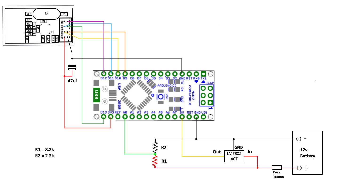
I have used a Rev8 Easy/Newbie board
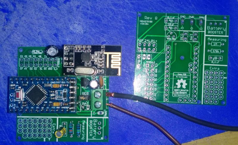
with a couple of tweaks
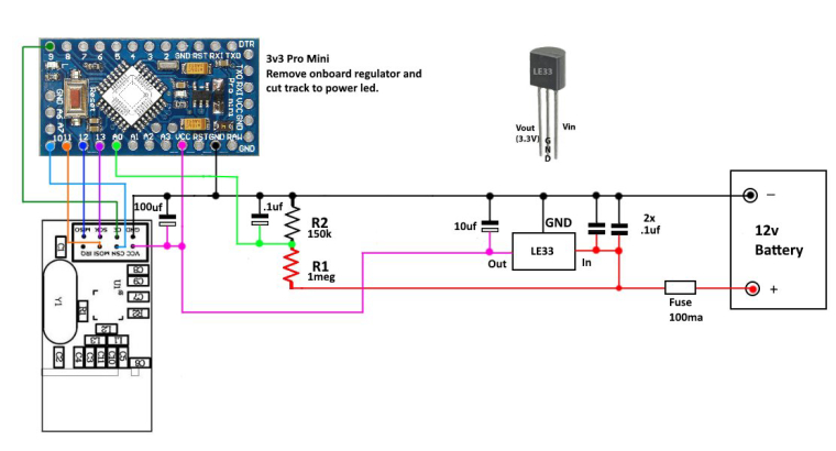
The circuit now looks something like this
And finally the sketch
/*Sketch for a MySensor node to monitor a 12v aux battery in a Camper Trailer * The node monitors battery voltage and reports back to the controller. Uses a 3v * Pro mini with power led and voltage regulator removed. * Voltage divider R1 1 megaohm R2 150 kilohms * */ #define MY_DEBUG // Enable debug prints to serial monitor #define MY_RADIO_NRF24 // Enable and select radio type attached #define MY_TRANSPORT_WAIT_READY_MS 3000 //set how long to wait for connection to establish before moving on. in milliseconds //#define MY_NODE_ID 15 #define MY_RF24_CHANNEL 84 // set channel used //#define MY_PARENT_NODE_ID 1 // set the parent node //#define MY_PARENT_NODE_IS_STATIC // force connection to parent node only. #include "MySensors.h" #define ID_S_MULTIMETERV 1 // Multimeter device for voltage measurement //unsigned long sleepTime = 15000; unsigned long sleepTime = 60000 * 30; // Sleep time between reads (in milliseconds) (Set to 30 min at present) int voltagePin = A0; // analog pin voltage sensor or voltage divider is connected to int voltSenseMax = 25000; // set to the maximum voltage in millivolts of your voltage divider input int sampleCount = 0; int sum = 0; // sum of samples taken int numSamples = 10; MyMessage msg_S_MULTIMETERv(ID_S_MULTIMETERV,V_VOLTAGE); void setup() { wait (5000); // give node a chance to fully boot on startup } void presentation() { sendSketchInfo("Camper Battery Sensor", "1.0"); // Send the sketch version information to the gateway and Controller present(ID_S_MULTIMETERV, S_MULTIMETER,"Camper Battery"); // Register Sensor to gateway } void loop() { uplinkCheck(); // call function to send data Serial.println("------ sleeping now ----- "); sleep(sleepTime); // sleep until next scheduled check Serial.println("------awake now--------"); wait (50); // small wait to allow to stabalise after sleep. } /*-------------------start of functions--------------------------*/ void uplinkCheck() { if (request( ID_S_MULTIMETERV, V_VOLTAGE)) { // request the current voltage data from the controller and check that the request was succsessful Serial.println("uplink established"); while (sampleCount < numSamples) { sum += analogRead(voltagePin); sampleCount++; delay(10); } int voltMilli = map((sum / 10),0,1023,0,voltSenseMax); // map the reading and get the result in millivolts send(msg_S_MULTIMETERv.set(voltMilli / 1000.0, 2)); // Divide by 1000 to convert back to volts to two decimal places, send data to controller. // send voltage message to gateway with 1 decimal place sampleCount = 0; sum = 0; } else{ Serial.println(" No uplink "); } } -
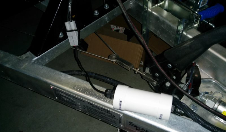
I was looking at how I would install this node in the camper and decided a permanent mounting might not be the best way to go. The camper is of fully steel construction and because it is meant for off road use when it is packed up it is sealed air tight to prevent water and dust from gaining entry. So this could make it difficult for the signal to get out.
Add to this that the camper is stored in a steel garage and located around 30m from the nearest repeater which is inside the house. So i decided to make the node an external plug in accessory to give it the best chance of making a connection.
The camper already has a heavy lead running directly from the batteries to the front of the A frame. This is used to supply power to the camper while travelling and also allows a solar panel to be connected.
So this seemed like the best spot to connect the node. The lead is fitted with an Anderson plug so connecting up would be easy as well. i hoped that by putting the node on the outside of the camper I would be able to get a stable connection back to the repeater.
The node was mounted into a small length of 50mm pvc tube, the easy/newbie board is a good fit.
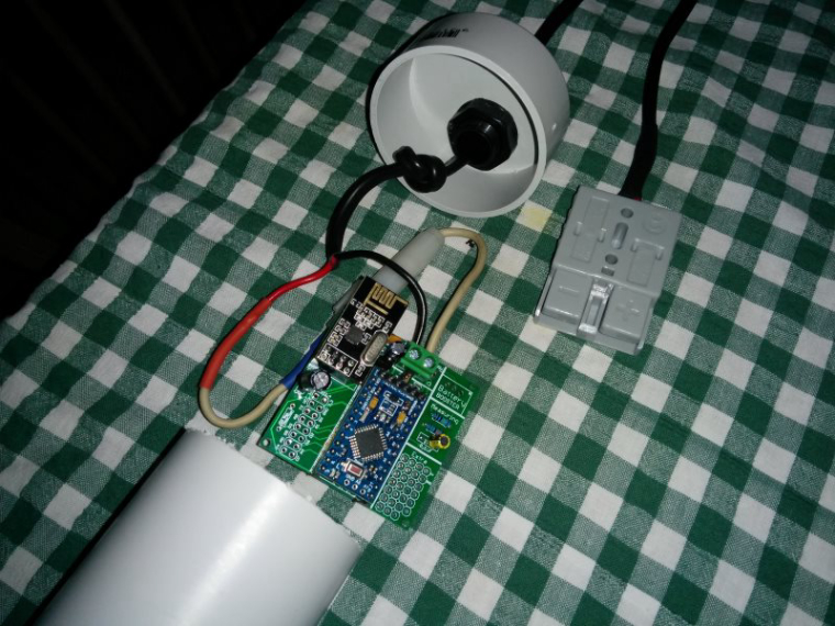
I have fitted a small length of cable with an Anderson plug, this allows a quick connect to the camper electricals. The finished node looks like this.
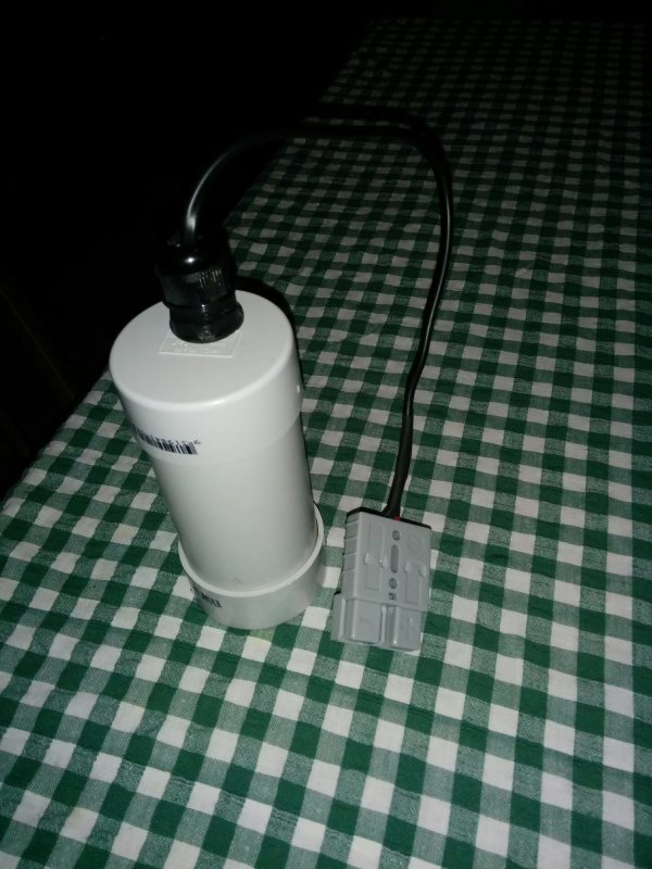
Then it just plugs into the camper. I found that it can hang over the front winch mount, this allows the body of the node to swing free away from other metal objects.
In testing i have the node transmitting every 15 min to get an idea of how it all goes. Unfortunately at the moment it sometimes misses the occasional send so it must be on the edge of range at the moment. Although it is not really critical that it makes connection every time i will have to see what else I can do to make it more reliable.
-
The low power node has continued to be unreliable, connecting only intermittently with the controller. It appears to be a power problem as the node works well when it is powered through the ftdi adaptor.
Voltage readings on the 3v line read 3.4v when on the ftdi and 3.27v through the LE33. Perhaps the LE33 at 100ma cannot keep up with the required demand?
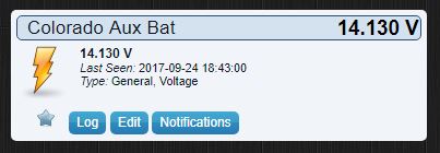
I have added another 47uf capacitor to the nrf supply and that seems to have improved things, so to continue testing I have now installed this unit into my Colorado as well . This will give it the same workout of coming and going that the other node gets and I will be able to compare their readings side by side to see if the voltage averaging this nodes uses makes any difference to reading stability.
-
The low power node has continued to be unreliable, connecting only intermittently with the controller. It appears to be a power problem as the node works well when it is powered through the ftdi adaptor.
Voltage readings on the 3v line read 3.4v when on the ftdi and 3.27v through the LE33. Perhaps the LE33 at 100ma cannot keep up with the required demand?
I have added another 47uf capacitor to the nrf supply and that seems to have improved things, so to continue testing I have now installed this unit into my Colorado as well . This will give it the same workout of coming and going that the other node gets and I will be able to compare their readings side by side to see if the voltage averaging this nodes uses makes any difference to reading stability.
@Boots33 - Im having a hard time to see exact caps on your voltage regulator. A double 0,1 (before) and 10uF (after) could improve the stability of the LE33.
Good thinking about the 47uF on the radio. Sometimes a 4.7 and sometimes 47uF does the job for me.
Controller: Proxmox VM - Home Assistant
MySensors GW: Arduino Uno - W5100 Ethernet, Gw Shield Nrf24l01+ 2,4Ghz
MySensors GW: Arduino Uno - Gw Shield RFM69, 433mhz
RFLink GW - Arduino Mega + RFLink Shield, 433mhz -
@Boots33 - Im having a hard time to see exact caps on your voltage regulator. A double 0,1 (before) and 10uF (after) could improve the stability of the LE33.
Good thinking about the 47uF on the radio. Sometimes a 4.7 and sometimes 47uF does the job for me.
@sundberg84 Thanks . I have a 0.1 and 10 on the reg at the moment . I will add another 0.1 and see if that helps.
I always used 4.7 on the nrf but since 2.1.1 I find 47uf works best for me now, although in this case it appears that closer to 100uf is what is needed for this node.
-
I was looking at how I would install this node in the camper and decided a permanent mounting might not be the best way to go. The camper is of fully steel construction and because it is meant for off road use when it is packed up it is sealed air tight to prevent water and dust from gaining entry. So this could make it difficult for the signal to get out.
Add to this that the camper is stored in a steel garage and located around 30m from the nearest repeater which is inside the house. So i decided to make the node an external plug in accessory to give it the best chance of making a connection.
The camper already has a heavy lead running directly from the batteries to the front of the A frame. This is used to supply power to the camper while travelling and also allows a solar panel to be connected.
So this seemed like the best spot to connect the node. The lead is fitted with an Anderson plug so connecting up would be easy as well. i hoped that by putting the node on the outside of the camper I would be able to get a stable connection back to the repeater.
The node was mounted into a small length of 50mm pvc tube, the easy/newbie board is a good fit.
I have fitted a small length of cable with an Anderson plug, this allows a quick connect to the camper electricals. The finished node looks like this.
Then it just plugs into the camper. I found that it can hang over the front winch mount, this allows the body of the node to swing free away from other metal objects.
In testing i have the node transmitting every 15 min to get an idea of how it all goes. Unfortunately at the moment it sometimes misses the occasional send so it must be on the edge of range at the moment. Although it is not really critical that it makes connection every time i will have to see what else I can do to make it more reliable.
@Boots33 For the radio, what if you used an NRF24L01+PA+LNA with an external antenna. you could put rubber washers on it to keep dirt out while having the antenna external to the other electronics.
Just a thought.
Vera Plus running UI7 with MySensors, Sonoffs and 1-Wire devices
Visit my website for more Bits, Bytes and Ramblings from me: http://dan.bemowski.info/ -
@Boots33 For the radio, what if you used an NRF24L01+PA+LNA with an external antenna. you could put rubber washers on it to keep dirt out while having the antenna external to the other electronics.
Just a thought.
@dbemowsk an external antenna is a good idea. I would like to avoid an amplified nrf if I could though simply because the le33 probably wouldn't cope.
Has anyone fitted an antenna socket to a standard nrf before.
I am happy enough with plugging in the unit at the moment but am also thinking of adding a few more features that will be useful when away. Then it would be better to have a mounted unit. -
@dbemowsk an external antenna is a good idea. I would like to avoid an amplified nrf if I could though simply because the le33 probably wouldn't cope.
Has anyone fitted an antenna socket to a standard nrf before.
I am happy enough with plugging in the unit at the moment but am also thinking of adding a few more features that will be useful when away. Then it would be better to have a mounted unit.@Boots33 there are versions with SMA connector that don't have the PA part ;)
I have also sometimes modified a "standard" NRF24L01+ module with a IPX connector
- Tomas
-
@Boots33 there are versions with SMA connector that don't have the PA part ;)
I have also sometimes modified a "standard" NRF24L01+ module with a IPX connector
Thanks @korttoma didn't know about those, have ordered a couple to give them a try. :)
They will come in handy if I decide to add further to this node and make it a permanent mount.
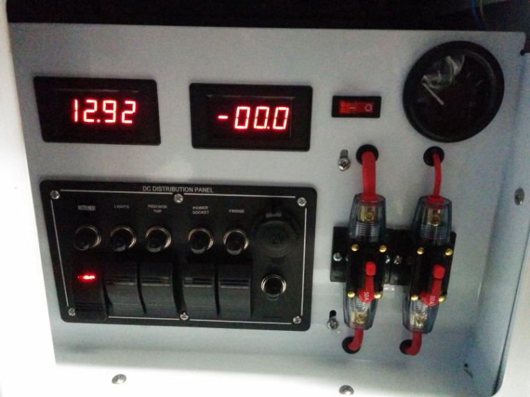
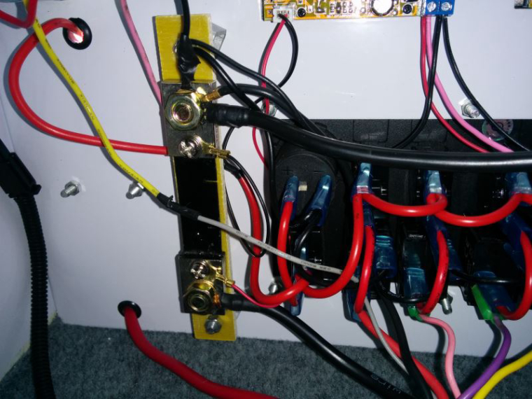
The camper has a control panel that includes an ammeter and volt gauge to help monitor the batteries, it is pretty basic but does a good job for what it is. It uses a shunt (75mv 100A) for the ammeter so I should be able to tap into that and add current draw to my data.
It also has a fridge box which has little ventilation at the moment so the fridge has to work hard in the hotter weather. We will be travelling into some desert areas next year so a temperature controlled ventilation system may be of use.
All just ideas at the moment will see how it progresses.
The control panel
The shunt is mounted on the rear of the panel
-
The low power node is now working as intended, the addition of an extra 47uf for the nrf power pin (there are two there now so a total of near 100uf) and an aditional .1uf on the LE33 power pin has made the node stable. It shows just how fussy the nrf can be about its power requirements.
I have made the changes to the wiring diagram in the previous post to reflect these additions.
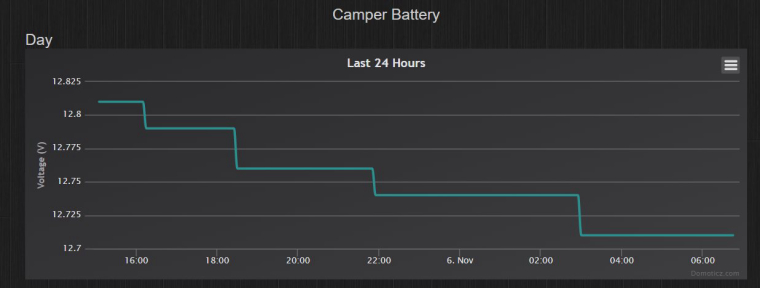
Have also now had a chance to compare the graphs of the two nodes in Domoticz and the low powered node with voltage averaging seems to give a much better result. In the following pictures you can see the steady drop of voltage over time for the low power node and a more zigzag line for the original node.
Will not know for sure until I add averaging to the first node, maybe the extra power draw is also affecting the reading.
The original node
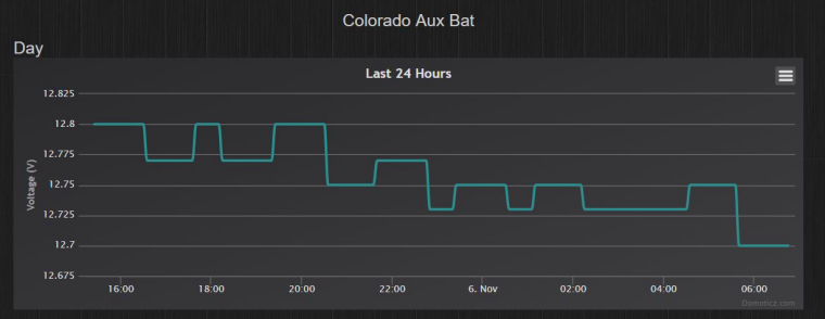
The low powered node. These are both connected to the same vehicle at the moment.
Hello! It looks like you're interested in this conversation, but you don't have an account yet.
Getting fed up of having to scroll through the same posts each visit? When you register for an account, you'll always come back to exactly where you were before, and choose to be notified of new replies (either via email, or push notification). You'll also be able to save bookmarks and upvote posts to show your appreciation to other community members.
With your input, this post could be even better 💗
Register Login