RFM69 antennas comparison

-
@gohan A straight wire will always have greater actual gain than a coil even though a quarter wave electrically with minimal ground plane.
On your findings on commercial v DIY coils, they are unlikely to be designed for the same centre frequency, but also typical shrouded helicals tend to be manufactured with very thin wire. The larger wire diameter coil will (even at identical design centre frequency) exhibit a slower rate of mismatch (SWR) as you move away from the centre frequency.
Where the objective is to use minimal power consumption on a battery powered node, efficient antennae can have significant effect when transmit power can be reduced for the same effective radiated power with a dipole etc...
-
@zboblamont so basically if I make a 66cm long straight wire is the best antenna I can make?
@gohan In comparison with a coil, the straight version will always behave more efficiently, but is also easiest to make correctly...
The issue I suspect your experiment uncovered is matching the exact wire diameter, turns and spacing to radiate precisely at the target frequency. You may find both are labelled as 433MHz for instance, but one is tuned to 470, the other at 435.... The 435 will be less a mismatch to the transmitter, thereby more efficient...
It is all a trade-off between location and how much intrusion into the space the antenna will be. You could have a node 100m away using minimal power into a full wavelength loop antenna (1/4 wave each side) using a metal shed wall as a reflector, there it does not intrude, in your kitchen it would....
-
Actually the coil spring antenna work sufficiently well for my needs anyway, since it is compact while the half coiled half straight antenna it is harder to fit in a small box.
@gohan Fair comment, as always it is a trade off...
-
@gohan Fair comment, as always it is a trade off...
@zboblamont @gohan (or anyone!) - could i ask your opinion about an PCB trace antenna (like a normal Nrf24l01+) would benifit in different orientations - and which one is the best?
For example, most of my MySensors nodes are laying down flat (and therefore the antenna is pretty much going through the horizontal plane). Would it benifit to have the radio standing so the PCB trace is in the vertical plane instead?
-
@sundberg84
for "best" pcb antennas, I would say : monopole (meandered or not), and inverted F. they also need tuning of course, regarding board geometry, antenna design etc.
but a well tuned whip antenna (with a wire) will always radiate in a better way, sort of 3d antenna compared to a 2d pcb antenna. -
@sundberg84
for "best" pcb antennas, I would say : monopole (meandered or not), and inverted F. they also need tuning of course, regarding board geometry, antenna design etc.
but a well tuned whip antenna (with a wire) will always radiate in a better way, sort of 3d antenna compared to a 2d pcb antenna.@scalz - ok, but if you take the Nrf24l01+ radio with its PCB antenna - is the antenna performing worse if the radio is lying down compared to if I have the radio standing up?
-
@zboblamont @gohan (or anyone!) - could i ask your opinion about an PCB trace antenna (like a normal Nrf24l01+) would benifit in different orientations - and which one is the best?
For example, most of my MySensors nodes are laying down flat (and therefore the antenna is pretty much going through the horizontal plane). Would it benifit to have the radio standing so the PCB trace is in the vertical plane instead?
@sundberg84 Not a great fan of PCB trace antennae, although I fully understand the advantage of small footprint. A whip or dipole antenna is problematic in terms of incorporating neatly, but will outperform the PCB a large factor.
Horizontal polarisation when received by a vertical cuts the gain considerably, at vhf/uhf etc up to 20dB, not sure the level at 2.4GHz as the wavelength is fairly short, but there will certainly be some attenuation on the outer fringes.
The other problem with horizontal polarisation is that the radiation lobe tends to be directional, so if nodes are at range you may have to compromise direction to 'catch' the edge of the radiation lobe. -
@sundberg84 Not a great fan of PCB trace antennae, although I fully understand the advantage of small footprint. A whip or dipole antenna is problematic in terms of incorporating neatly, but will outperform the PCB a large factor.
Horizontal polarisation when received by a vertical cuts the gain considerably, at vhf/uhf etc up to 20dB, not sure the level at 2.4GHz as the wavelength is fairly short, but there will certainly be some attenuation on the outer fringes.
The other problem with horizontal polarisation is that the radiation lobe tends to be directional, so if nodes are at range you may have to compromise direction to 'catch' the edge of the radiation lobe.@zboblamont - must admit I have a little hard time to fully follow your explanation and the terminology - but if I understand you correctly the answer is, yes I might have some loss if the radio is lying down.
Controller: Proxmox VM - Home Assistant
MySensors GW: Arduino Uno - W5100 Ethernet, Gw Shield Nrf24l01+ 2,4Ghz
MySensors GW: Arduino Uno - Gw Shield RFM69, 433mhz
RFLink GW - Arduino Mega + RFLink Shield, 433mhz -
@zboblamont - must admit I have a little hard time to fully follow your explanation and the terminology - but if I understand you correctly the answer is, yes I might have some loss if the radio is lying down.
@sundberg84 Sorry, yes there will be a loss.
This site may better demonstrate it graphically down the bottom...
link text -
@sundberg84 Sorry, yes there will be a loss.
This site may better demonstrate it graphically down the bottom...
link text@zboblamont - perfect!! Thanks!
Edit: from your link I could google more and found this: http://www.edaboard.com/thread294139.htmlBecause meander type is a monopole, the polarization is almost the same as a standard vertical monopole antenna (or the duck antenna in your setup).
So, the best coupling between antennas (giving the best communications between modules) is to place both antennas in vertical position (keeping the module using the printed antenna in the position shown in the picture).Edit2: https://forum.mysensors.org/topic/3459/nrf24l01-align-direction-position
https://forum.mysensors.org/topic/212/antenna-101 -
@zboblamont - perfect!! Thanks!
Edit: from your link I could google more and found this: http://www.edaboard.com/thread294139.htmlBecause meander type is a monopole, the polarization is almost the same as a standard vertical monopole antenna (or the duck antenna in your setup).
So, the best coupling between antennas (giving the best communications between modules) is to place both antennas in vertical position (keeping the module using the printed antenna in the position shown in the picture).Edit2: https://forum.mysensors.org/topic/3459/nrf24l01-align-direction-position
https://forum.mysensors.org/topic/212/antenna-101@sundberg84 The way to imagine field strength on an antenna is that it is circular looking on the end of a dipole, varying in strength from essentially zero at one end to max at the centre back to zero at the other end.
Under ideal conditions, the field is like the balloon explanation in the other link. Unless your receiver is hugely different in height to the sending antenna, the reception will be identical throughout 360 degrees at the same distance.
Rotate the antenna 90 degrees however and the the field forms principal lobes to front and rear, max facing centre on both sides, reducing to minimum facing the ends, viz this which makes the antenna directional compared to it's vertical orientation. -
I wanted to share my finding following my RFM69 signal scanner I previously built. I used 2 types of antennas:
-
Hand made like the one mentioned by @sundberg84 in [his project](https://www.openhardware.io/view/389/EasyNewbie-PCB-RFM69-HWW-edition-for-MySensors
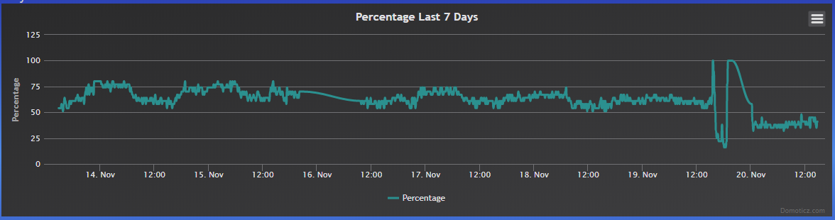
I let them run several hours reporting TX power since the new rfm69 driver adjusts power output to the default target RSSI of -80db
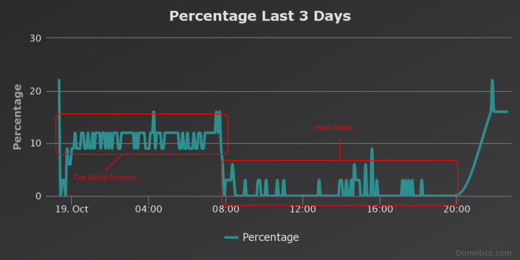
The test was done on the same spot (my desk) and the gw about 5 meters away (1 floor difference, and a couple of walls in between; gw running the coil spring antenna).
I am currently testing the SMA antennas and results are better than the hand made antenna with a TX power of 35/40% instead of 55/60%. My guess is the hand made antenna had to be squeezed inside the box getting a wrong orientation, while the SMA one is outside and it can stay perfectly vertical.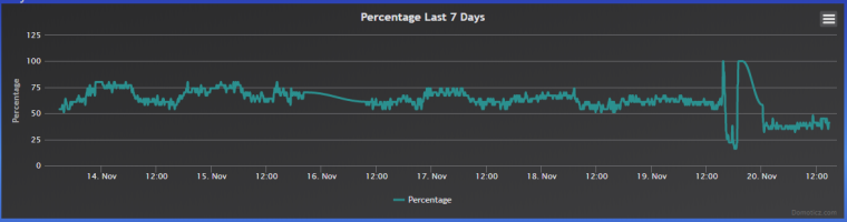
-
@Yveaux Excellent summary, yet well worth reading through.
What I found fascinating elsewhere was where 2.4GHz compressed PCB antennae such as the zig-zag pattern underperformed compared to their U or J type countertparts, despite identical claims as to gain, which is bidirectional.
-
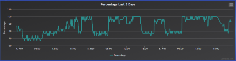
It is more or less related, but just this evening I had the garden sensor going out of range for 2 hours (from 6 to 8 pm). It happened a few time in the past but for shorter periods. Looking at the TX power it seems there is something affecting the communication from time to time. It would be nice to know the source since I live in the countryside and I have only another house near mine... I have to make other outdoor sensors to see if I get the same pattern
-
It is more or less related, but just this evening I had the garden sensor going out of range for 2 hours (from 6 to 8 pm). It happened a few time in the past but for shorter periods. Looking at the TX power it seems there is something affecting the communication from time to time. It would be nice to know the source since I live in the countryside and I have only another house near mine... I have to make other outdoor sensors to see if I get the same pattern
@gohan
Hi. i know that its 3 months + old discussion .but i only read now :)
i have the same problem,probably same time that hapens to you. my nrf24 modules between front gate and gateway stops comunicating at end of day.
My bet it that signal its already on limit ,(at 50m between gate and home), and at the end of day ,air humidity increase and signal just don't arrive. I already change antennas but signal strengh it's on limit and some days are worst than others.Now i will change all my nrf24 for rfm69's (they arrive today) and try again at 868mhz and simple wire antenna(dipole).
Just for confirm; are the grownd plane from rfm69hw good enought? or i need something more than a piece of wire on ANA pin ?i'm a arduino fan .Even sometimes don't undestanding how to use it :P
-
@gohan
Hi. i know that its 3 months + old discussion .but i only read now :)
i have the same problem,probably same time that hapens to you. my nrf24 modules between front gate and gateway stops comunicating at end of day.
My bet it that signal its already on limit ,(at 50m between gate and home), and at the end of day ,air humidity increase and signal just don't arrive. I already change antennas but signal strengh it's on limit and some days are worst than others.Now i will change all my nrf24 for rfm69's (they arrive today) and try again at 868mhz and simple wire antenna(dipole).
Just for confirm; are the grownd plane from rfm69hw good enought? or i need something more than a piece of wire on ANA pin ?@tmaster Pending @gohan's response, I suggest you try a simple 1/4 plain wire whip initially.
You are using not simply different devices with differing characteristics but different frequencies, penetration of 2.4GHz and 868MHz wavelengths are not the same, lower frequencies have better penetration.
Should you require additional gain either to reduce transmission power input, or to increase effective radiated power it is easy enough to add a mirror 1/4 later to make it a dipole should you desire... -
You could also use a PA LNA radio on the gateway and maybe on node. Also trying different antennae on the radio, as previously suggested, is an option. RFM69 have a good advantage of reportig signal strength (I published a small signal scanner for RFM69 in the My Project section) that gets handy in detecting blind spots.
Hello! It looks like you're interested in this conversation, but you don't have an account yet.
Getting fed up of having to scroll through the same posts each visit? When you register for an account, you'll always come back to exactly where you were before, and choose to be notified of new replies (either via email, or push notification). You'll also be able to save bookmarks and upvote posts to show your appreciation to other community members.
With your input, this post could be even better 💗
Register Login