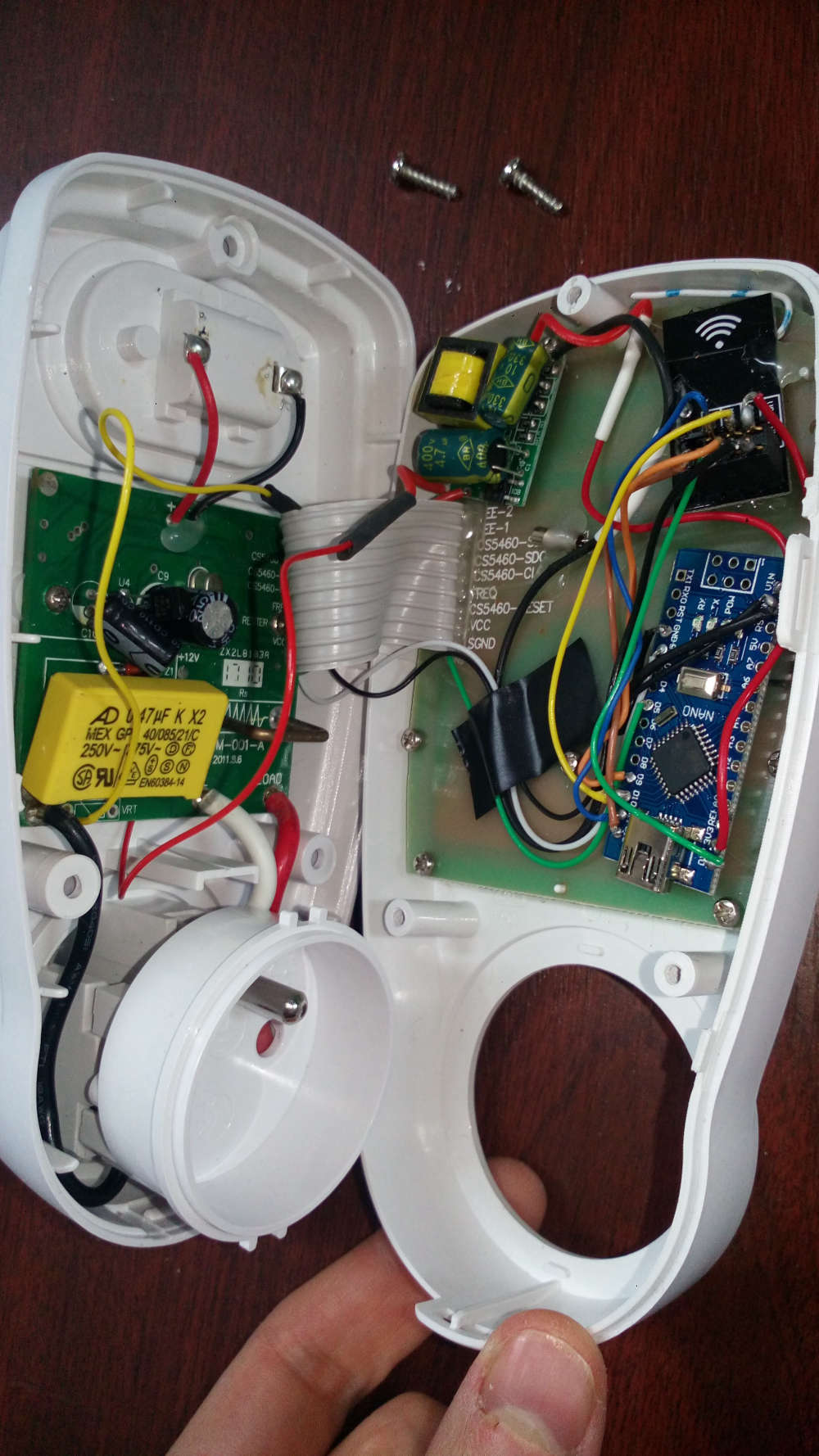
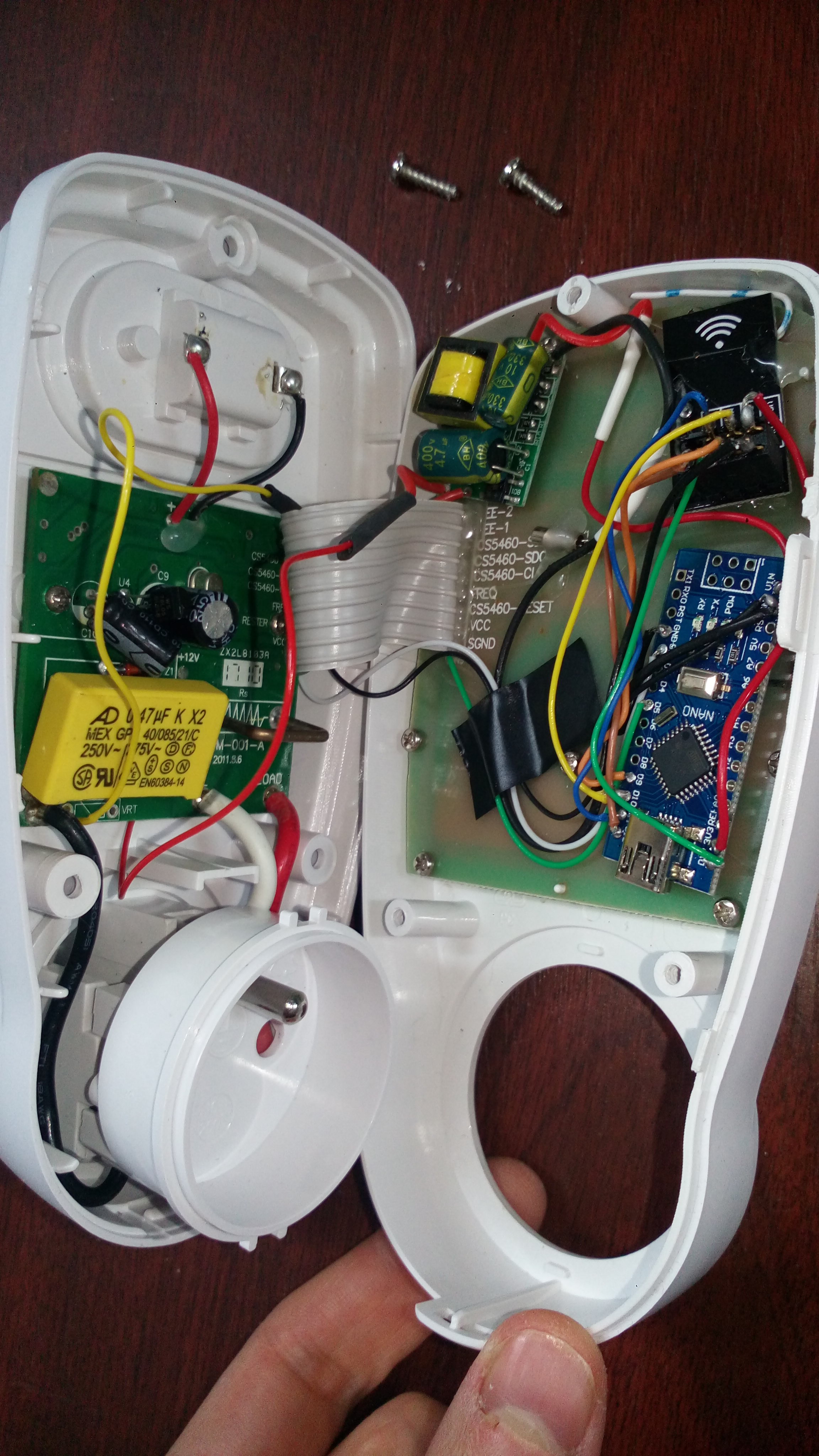
Power Meter with product energy power meter socket (based on IC CS5460A)
-
Hello,
I would like to use Karl's work on the hack of an energy power meter socket:
http://gizmosnack.blogspot.fr/2014/10/power-plug-energy-meter-hack.html
and add a mysensors node to retrieve the values in Domoticz.
I bought this one: https://www.amazon.fr/GreenBlue-GB202-consommation-dénergie-wattmètre/dp/B00E5BONDU/ref=sr_1_2?ie=UTF8&qid=1510248821&sr=8-2&keywords=wattmetre
It's the same model based on IC CS5460A (datasheet).I uploaded the sketch of Karl in a Arduino Nano, and i can read the values correctly by displaying them on 16x2 LCD screen.
Good news !
I modified my sketch, and it's OK: the values are read correctly.My sketch:
//Enable debug prints
//#define MY_DEBUG

// Enable and select radio type attached
#define MY_RADIO_NRF24

#include <MySensors.h>

#include <Wire.h>
#include <LiquidCrystal_I2C.h>

#define BACKLIGHT_PIN 3
#define En_pin 2
#define Rw_pin 1
#define Rs_pin 0
#define D4_pin 4
#define D5_pin 5
#define D6_pin 6
#define D7_pin 7

LiquidCrystal_I2C lcd(0x27,En_pin,Rw_pin,Rs_pin,D4_pin,D5_pin,D6_pin,D7_pin);

//#define CHILD_ID 5              // Id of the sensor child

const int CLKPin = 2; // Pin connected to CLK (D2 & INT0)
const int MISOPin = 5;  // Pin connected to MISO (D5)

//All variables that is changed in the interrupt function must be volatile to make sure changes are saved.
volatile int Ba = 0;   //Store MISO-byte 1
volatile int Bb = 0;   //Store MISO-byte 2
volatile int Bc = 0;   //Store MISO-byte 2
float U = 0;    //voltage
float P = 0;    //power
float ReadData[3] = {0, 0, 0}; //Array to hold mean values of [U,I,P]

volatile long CountBits = 0;      //Count read bits
volatile int Antal = 0;           //number of read values (to calculate mean)
volatile long ClkHighCount = 0;   //Number of CLK-highs (find start of a Byte)
volatile boolean inSync = false;  //as long as we ar in SPI-sync
volatile boolean NextBit = true;  //A new bit is detected


unsigned long SEND_FREQUENCY = 30000;
volatile unsigned int tension = 0;
volatile unsigned long watt = 0;
unsigned int oldTension = 0;
unsigned long oldWatt = 0;
unsigned long lastSend;

bool recupOK = false;

MyMessage wattMsg(CHILD_ID,V_WATT);
MyMessage voltMsg(CHILD_ID,V_VOLTAGE);


//Function that triggers whenever CLK-pin is rising (goes high)
void CLK_ISR(){
  //if we are trying to find the sync-time (CLK goes high for 1-2ms)
  if(inSync==false){
    ClkHighCount = 0;
    //Register how long the ClkHigh is high to evaluate if we are at the part wher clk goes high for 1-2 ms
    while(digitalRead(CLKPin)==HIGH){
      ClkHighCount += 1;
      delayMicroseconds(30);  //can only use delayMicroseconds in an interrupt.
    }
    //if the Clk was high between 1 and 2 ms than, its a start of a SPI-transmission
    if(ClkHighCount >= 33 && ClkHighCount <= 67){
       inSync = true;
    }
  }
  else{ //we are in sync and logging CLK-highs
    //increment an integer to keep track of how many bits we have read.
    CountBits += 1;
    NextBit = true;
  }
}


void setup()
{
    attachInterrupt(0, CLK_ISR, RISING);

    //Set the CLK-pin (D5) to input
    pinMode(CLKPin, INPUT);
    //Set the MISO-pin (D5) to input
    pinMode(MISOPin, INPUT);

    lastSend=millis();

    lcd.begin(16,2);               // initialize the lcd
    lcd.setBacklightPin(BACKLIGHT_PIN,POSITIVE);
    lcd.setBacklight(HIGH);
    lcd.setCursor(0,0);
    lcd.print("initialised");
}

void presentation()
{
	// Send the sketch version information to the gateway and Controller
	sendSketchInfo("Energy Power", "1.0");

	// Register this device as power sensor
	present(CHILD_ID, S_POWER);
}

void loop()
{
	// Only send values at a maximum frequency or woken up from sleep
	bool sendTime = (millis() - lastSend) > SEND_FREQUENCY;

	//do nothing until the CLK-interrupt occures and sets inSync=true
  if(inSync)
	{
		CountBits = 0;  //CLK-interrupt increments CountBits when new bit is received
		while(CountBits<40){}  //skip the uninteresting 5 first bytes
		CountBits=0;
		Ba=0;
		Bb=0;
		while(CountBits<24){  //Loop through the next 3 Bytes (6-8) and save byte 6 and 7 in Ba and Bb
		  if(NextBit == true){ //when rising edge on CLK is detected, NextBit = true in in interrupt.
			if(CountBits < 9){  //first Byte/8 bits in Ba
			  Ba = (Ba << 1);  //Shift Ba one bit to left and store MISO-value (0 or 1) (see http://arduino.cc/en/Reference/Bitshift)
			  //read MISO-pin, if high: make Ba[0] = 1
			  if(digitalRead(MISOPin)==HIGH){
				Ba |= (1<<0);  //changes first bit of Ba to "1"
			  }   //doesn't need "else" because BaBb[0] is zero if not changed.
			  NextBit=false; //reset NextBit in wait for next CLK-interrupt
			}
			else if(CountBits < 17){  //bit 9-16 is byte 7, stor in Bb
			  Bb = Bb << 1;  //Shift Ba one bit to left and store MISO-value (0 or 1)
			  //read MISO-pin, if high: make Ba[0] = 1
			  if(digitalRead(MISOPin)==HIGH){
				Bb |= (1<<0);  //changes first bit of Bb to "1"
			  }
			  NextBit=false;  //reset NextBit in wait for next CLK-interrupt
			}
		  }
		}
		if(Bb!=3){ //if bit Bb is not 3, we have reached the important part, U is allready in Ba and Bb and next 8 Bytes will give us the Power.
		  Antal += 1;  //increment for mean value calculations

		  //Voltage = 2*(Ba+Bb/255)
		  U=2.0*((float)Ba+(float)Bb/255.0);

		  //Power:
		  CountBits=0;
		  while(CountBits<40){}//Start reading the next 8 Bytes by skipping the first 5 uninteresting ones

		  CountBits=0;
		  Ba=0;
		  Bb=0;
		  Bc=0;
		  while(CountBits<24){  //store byte 6, 7 and 8 in Ba and Bb & Bc.
  			if(NextBit == true){
  			  if(CountBits < 9){
  				Ba = (Ba << 1);  //Shift Ba one bit to left and store MISO-value (0 or 1)
  				//read MISO-pin, if high: make Ba[0] = 1
  				if(digitalRead(MISOPin)==HIGH){
  				  Ba |= (1<<0);  //changes first bit of Ba to "1"
  				}
  				NextBit=false;
  			  }
  			  else if(CountBits < 17){
  				Bb = Bb << 1;  //Shift Ba one bit to left and store MISO-value (0 or 1)
  				//read MISO-pin, if high: make Ba[0] = 1
  				if(digitalRead(MISOPin)==HIGH){
  				  Bb |= (1<<0);  //changes first bit of Bb to "1"
  				}
  				NextBit=false;
  			  }
  			  else{
  				Bc = Bc << 1;  //Shift Bc one bit to left and store MISO-value (0 or 1)
  				//read MISO-pin, if high: make Bc[0] = 1
  				if(digitalRead(MISOPin)==HIGH){
  				  Bc |= (1<<0);  //changes first bit of Bc to "1"
  				}
  				NextBit=false;
  			  }
  			}
			}

		  //Power = (Ba*255+Bb)/2
      Ba=255-Ba;
      Bb=255-Bb;
      Bc=255-Bc;
		  P=((float)Ba*255+(float)Bb+(float)Bc/255.0)/2;

		  //Voltage mean
		  ReadData[0] = (U+ReadData[0]*((float)Antal-1))/(float)Antal;
		  //Current mean
		  ReadData[1] = (P/U+ReadData[1]*((float)Antal-1))/(float)Antal;
		  //Power mean
		  ReadData[2] = (P+ReadData[2]*((float)Antal-1))/(float)Antal;

      //Serial.print("U: ");
      //Serial.println(U,1);
      if (U > 250){
        U = oldTension;
      }
      if (P > 4000){
        P = 0;
      }
      watt = P;
      tension = U;
      float i = P / U;
      if (P == 0){ i = 0; }
      String texteT = "U: " + String(tension) + " - I: " + String(i);
      lcd.setCursor(0,0);
      lcd.print(texteT);
      texteT = "P: " + String(watt) + "             ";
      lcd.setCursor(0,1);
      lcd.print(texteT);

		  if(Antal==10){ //every 10th 70-package = every ~10s
        //transmit ReadData-array to nRF or Wifi-module here:
        //transmission function here...

        //Reset ReadData-array
        ReadData[0] = 0;
        ReadData[1] = 0;
        ReadData[2] = 0;
        //reset mean-value counter
        Antal=0;
      }
      inSync=false;  //reset sync variable to make sure next reading is in sync.
			recupOK = true;
		}

		if(Bb==0){  //If Bb is not 3 or something else than 0, something is wrong!
		  inSync=false;
		}
	}

	if (recupOK && sendTime)
	{
		// New watt value has been calculated
		if (watt != oldWatt) {
			send(wattMsg.set(watt));  // Send watt value to gw

			Serial.print("Watt:");
			Serial.println(watt);
			oldWatt = watt;
		}

		if (tension != oldTension) {
		  send(voltMsg.set(tension));  // Send watt value to gw

		  Serial.print("Tension:");
		  Serial.println(tension);
		  oldTension = tension;
		}

		lastSend = millis();
		recupOK = false;
	}
}
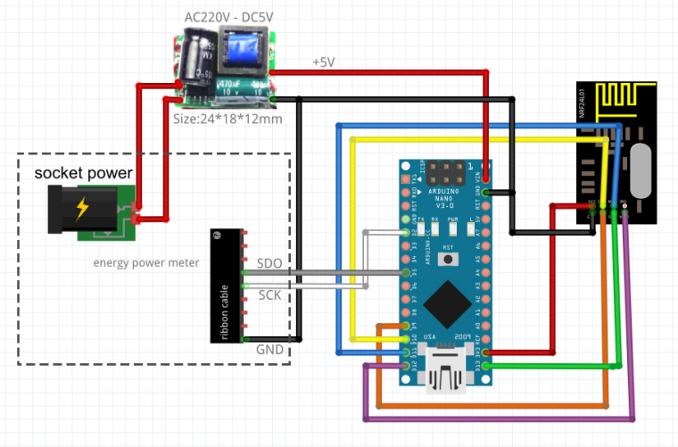
Schema:

Note:
On PCB of energy power meter, there is a regulator L7805, with +12V in input.
But the step-down power supply (combo condo+resistor with protect diode zener) for PCB is calculated for a fixed and known current.
Add Arduino and NRF24L01 increase this current and so the values with C+R are wrong for to have +12V (It's more than +12V and diode zener turn on for protect electronics IC).
So we have to add a small step-down power supply for arduino+nrf24L01./!\ Warning:
Don't connect the USB port of arduino on PC with the energy power meter socket connected on wall socket: The DC ground is not isolated from the electrical neutral and this causes a leakage current.
Your differential circuit breaker turns on.The solution is to use a serial connection with optocoupler for isolate the 2 parts (arduino and PC).


