Wemos D1 mini GW + DHT22 + Relay shield

-
Hi I'm a newcomer, I need to help with my sketch. I try to run the temperature and humidity sensor for the relay. I only run DHT under Verou Plus for inclusion mode does not find a relay. anyone help me?
/**
 * The MySensors Arduino library handles the wireless radio link and protocol
 * between your home built sensors/actuators and HA controller of choice.
 * The sensors forms a self healing radio network with optional repeaters. Each
 * repeater and gateway builds a routing tables in EEPROM which keeps track of the
 * network topology allowing messages to be routed to nodes.
 *
 * Created by Henrik Ekblad <henrik.ekblad@mysensors.org>
 * Copyright (C) 2013-2015 Sensnology AB
 * Full contributor list: https://github.com/mysensors/Arduino/graphs/contributors
 *
 * Documentation: http://www.mysensors.org
 * Support Forum: http://forum.mysensors.org
 *
 * This program is free software; you can redistribute it and/or
 * modify it under the terms of the GNU General Public License
 * version 2 as published by the Free Software Foundation.
 *
 *******************************
 *
 * REVISION HISTORY
 * Version 1.0 - Henrik EKblad
 * Contribution by a-lurker and Anticimex,
 * Contribution by Norbert Truchsess <norbert.truchsess@t-online.de>
 * Contribution by Ivo Pullens (ESP8266 support)
 *
 * DESCRIPTION
 * The EthernetGateway sends data received from sensors to the WiFi link.
 * The gateway also accepts input on ethernet interface, which is then sent out to the radio network.
 *
 * VERA CONFIGURATION:
 * Enter "ip-number:port" in the ip-field of the Arduino GW device. This will temporarily override any serial configuration for the Vera plugin.
 * E.g. If you want to use the defualt values in this sketch enter: 192.168.178.66:5003
 *
 * LED purposes:
 * - To use the feature, uncomment WITH_LEDS_BLINKING in MyConfig.h
 * - RX (green) - blink fast on radio message recieved. In inclusion mode will blink fast only on presentation recieved
 * - TX (yellow) - blink fast on radio message transmitted. In inclusion mode will blink slowly
 * - ERR (red) - fast blink on error during transmission error or recieve crc error
 *
 * See http://www.mysensors.org/build/esp8266_gateway for wiring instructions.
 * nRF24L01+  ESP8266
 * VCC        VCC
 * CE         GPIO4
 * CSN/CS     GPIO15
 * SCK        GPIO14
 * MISO       GPIO12
 * MOSI       GPIO13
 * GND        GND
 *
 * Not all ESP8266 modules have all pins available on their external interface.
 * This code has been tested on an ESP-12 module.
 * The ESP8266 requires a certain pin configuration to download code, and another one to run code:
 * - Connect REST (reset) via 10K pullup resistor to VCC, and via switch to GND ('reset switch')
 * - Connect GPIO15 via 10K pulldown resistor to GND
 * - Connect CH_PD via 10K resistor to VCC
 * - Connect GPIO2 via 10K resistor to VCC
 * - Connect GPIO0 via 10K resistor to VCC, and via switch to GND ('bootload switch')
 *
  * Inclusion mode button:
 * - Connect GPIO5 via switch to GND ('inclusion switch')
 *
 * Hardware SHA204 signing is currently not supported!
 *
 * Make sure to fill in your ssid and WiFi password below for ssid & pass.
 */

#include <EEPROM.h>
#include <SPI.h>
#include <DHT.h>

// Enable debug prints to serial monitor
#define MY_DEBUG

// Use a bit lower baudrate for serial prints on ESP8266 than default in MyConfig.h
#define MY_BAUD_RATE 9600

// Enables and select radio type (if attached)
//#define MY_RADIO_NRF24
//#define MY_RADIO_RFM69

#define MY_GATEWAY_ESP8266

#define MY_ESP8266_SSID "ZZZ"
#define MY_ESP8266_PASSWORD "xxx"

// Enable UDP communication
//#define MY_USE_UDP

// Set the hostname for the WiFi Client. This is the hostname
// it will pass to the DHCP server if not static.
//define MY_ESP8266_HOSTNAME "ESP8266-sensorNode1"

// Enable MY_IP_ADDRESS here if you want a static ip address (no DHCP)
#define MY_IP_ADDRESS 192,168,2,45

// If using static ip you need to define Gateway and Subnet address as well
#define MY_IP_GATEWAY_ADDRESS 192,168,2,1
#define MY_IP_SUBNET_ADDRESS 255,255,255,0

// The port to keep open on node server mode
#define MY_PORT 5003

// How many clients should be able to connect to this gateway (default 1)
#define MY_GATEWAY_MAX_CLIENTS 2

// Controller ip address. Enables client mode (default is "server" mode).
// Also enable this if MY_USE_UDP is used and you want sensor data sent somewhere.
//#define MY_CONTROLLER_IP_ADDRESS 192, 168, 178, 68

// Enable inclusion mode
#define MY_INCLUSION_MODE_FEATURE

// Enable Inclusion mode button on gateway
// #define MY_INCLUSION_BUTTON_FEATURE
// Set inclusion mode duration (in seconds)
#define MY_INCLUSION_MODE_DURATION 60
// Digital pin used for inclusion mode button
//#define MY_INCLUSION_MODE_BUTTON_PIN  3


// Flash leds on rx/tx/err
// #define MY_LEDS_BLINKING_FEATURE
// Set blinking period
// #define MY_DEFAULT_LED_BLINK_PERIOD 300

// Led pins used if blinking feature is enabled above
//#define MY_DEFAULT_ERR_LED_PIN 16  // Error led pin
//#define MY_DEFAULT_RX_LED_PIN  16  // Receive led pin
//#define MY_DEFAULT_TX_LED_PIN  16  // the PCB, on board LED


#if defined(MY_USE_UDP)
  #include <WiFiUDP.h>
#else
  #include <ESP8266WiFi.h>
#endif

#include <MySensors.h>


//-------- DHT22 related definitions ----->>>
// Set this to the pin you connected the DHT's data pin to
#define DHTPIN 2
#define DHTTYPE DHT22   // DHT 22  (AM2302)
// Set this offset if the sensor has a permanent small offset to the real temperatures
#define SENSOR_TEMP_OFFSET 0

#define CHILD_ID_HUM 0
#define CHILD_ID_TEMP 1

#define RELAY_1 D3 // Arduino Digital I/O pin number for first relay (second on pin+1 etc)
#define NUMBER_OF_RELAYS 1 // Total number of attached relays
#define RELAY_ON 1 // GPIO value to write to turn on attached relay
#define RELAY_OFF 0 // GPIO value to write to turn off attached relay

float lastTemp;
float lastHum;
bool metric = true;
float temperature;

// Sleep time between sensor updates (in milliseconds)
// Must be >1000ms for DHT22 and >2000ms for DHT11
static const uint64_t UPDATE_INTERVAL = 15000;

MyMessage msgHum(CHILD_ID_HUM, V_HUM);
MyMessage msgTemp(CHILD_ID_TEMP, V_TEMP);
DHT dht(DHTPIN, DHTTYPE);
//<<<----- DHT22 related definitions --------


void before()
{
for (int sensor=1, pin=RELAY_1; sensor<=NUMBER_OF_RELAYS; sensor++, pin++) {
// Then set relay pins in output mode
pinMode(pin, OUTPUT);
// Set relay to last known state (using eeprom storage)
digitalWrite(pin, loadState(sensor)?RELAY_ON:RELAY_OFF);
}
}

void setup() {
   dht.begin();
}

void presentation() {
    // Send the sketch version information to the gateway
  sendSketchInfo("TemperatureAndHumidity", "1.1");

  // Register all sensors to gw (they will be created as child devices)
  present(CHILD_ID_HUM, S_HUM);
  present(CHILD_ID_TEMP, S_TEMP);

   //sendSketchInfo("Relay", "1.0");
 for (int sensor=1, pin=RELAY_1; sensor<=NUMBER_OF_RELAYS; sensor++, pin++) {
  // Register all sensors to gw (they will be created as child devices)
  present(sensor, S_BINARY);
}
}

void loop() {
  // Get temperature from DHT library
  temperature = dht.readTemperature();
  wait(2000);
  Serial.print("Temperature:");
  Serial.println(temperature);
  if (isnan(temperature)) {
    Serial.println("Failed reading temperature from DHT!");
  } else if (temperature != lastTemp) {
    // Only send temperature if it changed since the last measurement or if we didn't send an update for n times
    lastTemp = temperature;

    // Reset no updates counter
    temperature += SENSOR_TEMP_OFFSET;
    send(msgTemp.set(temperature, 1));
  }
  // Get humidity from DHT library
  float humidity = dht.readHumidity();
  wait(2000);
  Serial.print("Humidity:");
  Serial.println(humidity);
  if (isnan(humidity)) {
    Serial.println("Failed reading humidity from DHT");
  } else if (humidity != lastHum) {
    // Only send humidity if it changed since the last measurement or if we didn't send an update for n times
    lastHum = humidity;
    send(msgHum.set(humidity, 1));}
    }
void receive(const MyMessage &message)
{
// We only expect one type of message from controller. But we better check anyway.
if (message.type==V_STATUS) {
// Change relay state
digitalWrite(message.sensor-1+RELAY_1, message.getBool()?RELAY_ON:RELAY_OFF);
// Store state in eeprom
saveState(message.sensor, message.getBool());
// Write some debug info
Serial.print("Incoming change for sensor:");
Serial.print(message.sensor);
Serial.print(", New status: ");
Serial.println(message.getBool());}

  wait(UPDATE_INTERVAL);
}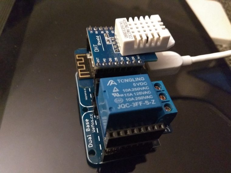
Hello! It looks like you're interested in this conversation, but you don't have an account yet.
Getting fed up of having to scroll through the same posts each visit? When you register for an account, you'll always come back to exactly where you were before, and choose to be notified of new replies (either via email, or push notification). You'll also be able to save bookmarks and upvote posts to show your appreciation to other community members.
With your input, this post could be even better 💗
Register Login