CNC PCB milling


  • @neverdie for the cable issue I ordered this cable organizer spiral, although not yet installed it 🙂


  • Hero Member

    @andrew said in CNC PCB milling:

    with chilipeppr (in case of grbl 0.9j go for http://chilipeppr.com/grbl , for 1.1.f go for http://chilipeppr.com/jpadie) you can quickly run its default logo engraving path for testing / demo purposes.

    Thanks! That provided exactly what I was looking for. I ran the demo with no etching bit installed, and at first both X and Y seemed to be working, but the adapter coupling eventually loosened on both of them to the point where there was no longer X and Y movement. I've re-tightened tem, and it's working again. I hope it lasts.

    Not sure where I should go next from here though.


  • @neverdie said in CNC PCB milling:

    @andrew said in CNC PCB milling:

    with chilipeppr (in case of grbl 0.9j go for http://chilipeppr.com/grbl , for 1.1.f go for http://chilipeppr.com/jpadie) you can quickly run its default logo engraving path for testing / demo purposes.

    Thanks! That provided exactly what I was looking for. I ran the demo with no etching bit installed, and at first both X and Y seemed to be working, but the adapter coupling eventually loosened on both of them to the point where there was no longer X and Y movement. I've re-tightened tem, and it's working again. I hope it lasts.

    Not sure where I should go next from here though.

    so, as this machine does not have limit switches installed, it is your responsibility to move the gantry to a position, from where you would like to start the job and which provides enough space for each direction movement. usually you have to set a relative zero at the given starting point.

    what is next? did you adjusted the stepper drivers? if not, then do it (I shared the link above). this is necessary to be sure, that the steppers will be powered with enough current (so they will be powerful enough for the given speed related movement and to provide enough force) or will not be overdriven.

    then, I would say try to engrave the chilipeppr logo to a soft material first, have some experience with the cnc.
    then, as I mentioned, discover the flatcam tool and try to create an isolation routing job for a test pcb.
    I already mentioned my confirmed settings for the given jobs (edge / hole milling, isolation routing).
    you should sacrifice some boards for your experience 🙂

    also, try to find your ideal g code sender tool by trying multiple ones.


  • Hero Member

    I don't see any plugs on the woodpecker board that are designated for connecting to a touch plate. So, I guess it's configured using the woodpecker header pins? How is that best set up?

    By the way, after re-tightening the set-screws on the adapters used to connect the step-motors to the screw rods, they seem to be holding now and not slipping loose. I take it back, one of them just came loose again. 😞


  • Hero Member

    @neverdie said in CNC PCB milling:

    one of them just came loose again

    And now the other one did too. Is anyone using a threadlocker on the set screws to keep this from happening?

    I think I'll put on some locktite and let it dry overnight and then see if it still happens tomorrow. I'll start with just the threaded rods.

    Anyhow, the good news is that the heat sinks plainly did not short out the GRBL controller boards. I guess the adhesive must act as an electrical insulator.


  • Hero Member

    Thinking about it now, an alternative might be to grind one side of the threaded rod flat in the region where it fits into the adapter. That would match the concept of the motor rotor, where that has already been done.

    Ideally I would notch it in just the region where the set screw makes contact. I suppose I could do that with a Dremel.

    Investigating now, I see that the adapter came loose on the motor rotor also. So, I think locktite will be a must.

    http://www.loctiteproducts.com/tds/T_LKR_BLUE_tds.pdf

    Looking at the datasheet, it takes 24 hours to cure.


  • Hero Member

    Well, humbug! I'm all out. Maybe tomorrow I'll buy the red threadlocker, which is even stronger.


  • Hero Member

    @rmtucker Which g-code sender is it that you like best?


  • @neverdie, or anyone else that can answer this with some logic, just because the topic came up. Why does Loctite red come in a blue container and loctite blue come in a red container?
    0_1513751591321_cf4dc6b4-34f3-453c-a624-05994fbca118-image.png


  • Mod

    @dbemowsk said in CNC PCB milling:

    Why does Loctite red come in a blue container and loctite blue come in a red container?

    Made in China?


  • Hero Member

    Probably historical reasons.


  • @yveaux LOL


  • Hero Member

    Probably a committee decision. Half liked red, and the other half liked blue. They were deadlocked, and this was their compromise decision. 😆


  • @neverdie for the touch sensing you should use A5 connector from the headers, connecting it to the actual tool (bit), then a gnd (header's bottom row) connecting to the pcb's surface.

    for the tool connection I use crocodile clamps.

    screws: you did not fasten them enough. at the beginning I also missed some endpoints, but since I put the cnc together, I had no issue with any of my screws.


  • @andrew for first go for a single touch probing instead of a whole autoleveling session.
    just for testing purposes, start the touch probing from a higher position and touch the gnd wire directly to the spindle's tool to see whether it stops or not. if not, you should stop it manually from the gui, otherwise it could break the tool.
    if everything works well (so you proved that you connections to the pins and the belonging settings are ok), then you can run the simple touch probes or the autoleveling as well.


  • Hardware Contributor

    @neverdie said in CNC PCB milling:

    Is anyone using a threadlocker on the set screws to keep this from happening?

    For one that will probably buy the same CNC could you document how you solve this with a picture?


  • @neverdie said in CNC PCB milling:

    @rmtucker Which g-code sender is it that you like best?

    I am not using a g-code sender,i am using mach3.
    But i have just started playing with grbl and bCNC seems to do most things.


  • @neverdie one more think I forgot to mention: after I assembled the cnc, I used a little wd40 across each axis and moved each from one end to another. it helped for smooth and "barrier-free" movements.


  • Hero Member

    @andrew said in CNC PCB milling:

    you should use A5 connector

    Does using A5 somehow automagically just work, or does it require additional software configuration?


  • Hero Member

    @sundberg84 said in CNC PCB milling:

    @neverdie said in CNC PCB milling:

    Is anyone using a threadlocker on the set screws to keep this from happening?

    For one that will probably buy the same CNC could you document how you solve this with a picture?

    OK, here is what I'm doing in pictures. I'm applying blue 242 Loctite:
    0_1513780511391_loctite.jpg
    to the threads of the 4 set screws on the coupler:
    0_1513780537893_coupler.jpg
    That should keep them from loosening up after they are screwed into position. Note, you have at most 10 minutes of working time before it sets.


  • Hero Member

    I applied it to the motor set screws first and let it set:
    0_1513782061856_magnet.jpg
    Note: I used rare earth magnets to help secure the set screw to the allen wrench. That insures that the set screw doesn't drop off and disappear somewhere on the floor. Works great.

    The couplers are made from anodized aluminum, so I'm not sure how well the loctite will work on them. However, I think it will still work, as the set screws themselves are steel.


  • Hero Member

    I found an intro to bCNC:
    Shapeoko 3 bCNC Beginner Tutorial – 08:40
    — BluegrassRC

    It looks easy and intuitive, so I'll probably go with that.

    As usual, it's the software that has the best tutorial that wins.


  • @neverdie I used to use nail varnish on threads as it was just as effective, even though it annoyed the partner whose nail varnish it was. It is not the bond between the metals which is that important, it is adding resistance between the threads to prevent unscrewing, were it to completely bond, you would shear the bolt before it was removed, which is a whole lot of trouble....


  • Hero Member

    @zboblamont said in CNC PCB milling:

    @neverdie I used to use nail varnish on threads as it was just as effective, even though it annoyed the partner whose nail varnish it was. It is not the bond between the metals which is that important, it is adding resistance between the threads to prevent unscrewing, were it to completely bond, you would shear the bolt before it was removed, which is a whole lot of trouble....

    Does nail varnish cure anaerobically in the presence of metal ions? That seems to be much of the theory behind thread lockers.

    I thought nail varnish cured by evaporation.

    In any case, I wiped off the excess loctite, because it might never dry (or, at least, take a long while to do so).

    I think the loctite is likely to work, since Andrew had success without anything but torquing it down hard. On the other hand, maybe his is threaded differently than what came in my kit.


  • @neverdie said in CNC PCB milling:

    @andrew said in CNC PCB milling:

    you should use A5 connector

    Does using A5 somehow automagically just work, or does it require additional software configuration?

    it should work by default


  • @neverdie Torquing down correctly normally prevents threads unwinding, but have seen bolts come loose with vibration on occasion. Only ever used loctite or equivalent on cylinder head bolts, particularly alloy heads, it never actually sets solid and is oil etc resistant.
    Although lacquer or plastic paints do harden, as a plastic filler between the threads, it increases contact friction, yet will shear to permit removal of the bolt when necessary. Typical threads do not fully engage metal to metal, the clearance is essential to allow the nut to be run on the bolt.
    Loctite is fine if you have it already, nail varnish works fine for me in non oily scenarios.


  • Hero Member

    I've retried it now, and so far it's not coming lose. 🙂

    I added some machine oil on the rods and screws, and that seems to have helped. Before that, there were some areas where the screw rod on the y-axis was binding, but not now.


  • Hero Member

    Are you guys running bCNC under Linux? Because installing it under Windows is proving to be challenging....


  • @neverdie yep, I've a linux vm for flatcam and bcnc.


  • @neverdie
    Linux for me too.Never used windows in years☺


  • Hero Member

    Here's the machine oil I'm using. As you can tell from the manufacturer, it's meant for sewing machines and similar:
    0_1513883937810_oil1.jpg0_1513884033669_oil2.jpg


  • Hero Member

    Well, now that I found this pulldown in Chilipeppr, I might stick with it a while longer:
    0_1513887938761_axes.png


  • Hero Member

    The strange thing is that the Chilipeppr demo seems to mill at z=0.000. So, if I were to try to etch the pattern for real, I would have to "zero" z at an actual z value of, say, z=-0.5 or something (whatever depth I wanted it to etch at).

    Is that normal?

    Anyhow, I've been through multiple trial iterations with no bit installed and with the spindle disabled, and during all that the X and Y couplers have not come loose. So, I think that the Locktite has lived up to its name and solved the problem I was having earlier. 🙂


  • @neverdie said in CNC PCB milling:

    The strange thing is that the Chilipeppr demo seems to mill at z=0.000. So, if I were to try to etch the pattern for real, I would have to "zero" z at an actual z value of, say, z=-0.5 or something (whatever depth I wanted it to etch at).

    Is that normal?

    Anyhow, I've been through multiple trial iterations with no bit installed and with the spindle disabled, and during all that the X and Y couplers have not come loose. So, I think that the Locktite has lived up to its name and solved the problem I was having earlier. 🙂

    yes, the chilipeppr demo works like this. but keep in mind, that for "real" isolation milling, the milling depth which you used during the g code generation will be calculate from the relative z zero, so in that case you really have to set z0 to the pcb surface.


  • Hero Member

    Disaster. Out of the blue, it suddenly just stopped working. Now I can't get it to spin the spindle or move in any x, y, or z direction. Gcode appears to be sent to it, and it does respond to me if I send it a '$" through the Chilipeppr console window. Just no movement whatsoever.

    I removed the heatsinks, as a possible culprit, but still no go.

    Suggestions on how to diagnose it?


  • Hero Member

    I found the problem: bad power supply brick. It is supplying no voltage at all. 😞

    The power brick that came as part of the kit says it is rated at 24v dc 5.62amp. Is that enough, or should I get something that can do more amps?


  • @neverdie oh 😞 if you have a chance to power the cnc from a variable current power supply, then check the current it drains by starting from low to higher current. if it eats lot, maybe there is a short somewhere. you could also try to open the power supply and find a fuse.
    good luck!


  • @neverdie I've a PS with the same parameters. it is enough.


  • Hero Member

    I don't have much optimism that the cheap-ass power supply that came with the kit can be repaired (well, not by me anyway).

    I ordered a 6amp one as a replacement, just to have a little more headroom:
    https://www.amazon.com/gp/product/B01AJQ9G2C/ref=oh_aui_detailpage_o01_s00?ie=UTF8&psc=1

    It may turn out to be cheap-ass also, but I can get it tomorrow, so I'm rolling the dice.

    If that burns out too, then there's this one, which looks more beefy and would be my first choice, but will take a week to receive it:
    https://www.amazon.com/gp/product/B01J19G00E/ref=oh_aui_detailpage_o00_s00?ie=UTF8&psc=1


  • Hero Member

    Dang. I cancelled the order, as I'm not sure whether its 5.5mmx2.1mm barrel jack will fit or whether a 5.5mm x2.5mm is required.

    Looks as though the barrel on the woodpeck is 2.5mm inside diameter....


  • Hero Member

    Powering it from a variable power supply, it apparently works. Here's the etching on a piece of plywood:
    0_1513906179776_logo.jpg
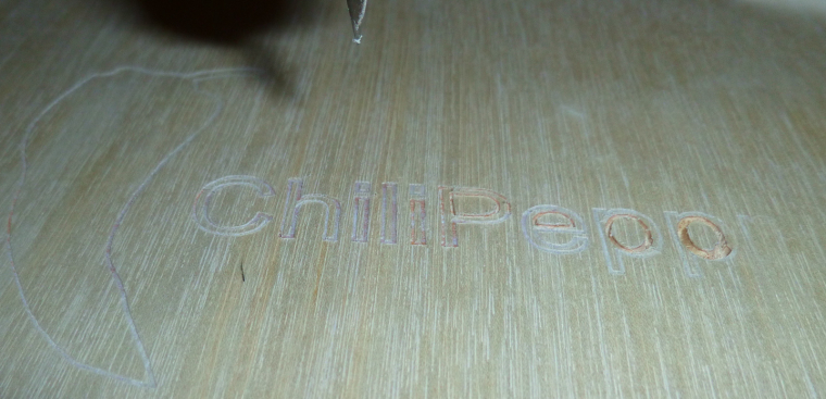
    I watched the current being drawn, and it appeared to always be below 1 amp. The variable power supply can supply up to 5 amps, so no problem there as far as I can see.

    The etching that it did was a bit weird: deep cuts in the inside diameter of the P's, but only faint cuts just outside. The R was barely even touched at all. The surface doesn't feel sufficiently non-flat to account for that.

    Ideas as to what's going wrong there?


  • Hero Member

    Here is a contextual photo:
    0_1513907110706_context.jpg
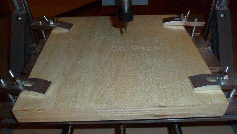
    The clamps are holding the board very securely.


  • Hero Member

    After thinking about it, my hypothesis is that the feedrate is too high. I have it set to 1 in ChilliPeppr. I think maybe it comes down rapidly to the programmed height, but if it meets resistance then it skips some motor steps. Since it's open loop, it doesn't know. Then it dwells at that depth until it picks up the bit and relocates. I'll try a slower feedrate and see if it makes a difference.


  • Hero Member

    Maybe the bit is too dull as well. It's one of the freebies that came with the kit.


  • Hero Member

    Also, what is the preferred way to tighten the ER11 chuck? So far, I did it just by hand, which seems to have been good enough. However, maybe a better practice is to give it a 1/4 turn further tightening using wrenches after that? How are others here approaching that?


  • @neverdie for er11 fastening you should use two wrenches.

    if you loose steps during the milling, then with the given feed rate / depth / spindle speed combination the cnc / spindle / steppers are not powerful enough.

    if you wood milling depth is not constant then:

    • the wood is not flat
    • the cnc bad is not flat
    • the cnc x axis is not horizontal

    my availability for the next couple of days will be quite limited, so I wish you good luck for experiencing the router and for the first PCBs!


  • @neverdie said in CNC PCB milling:

    Also, what is the preferred way to tighten the ER11 chuck? So far, I did it just by hand, which seems to have been good enough. However, maybe a better way is to give it a 1/4 turn further tightening using wrenches after that? How are others here approaching that?

    +1 for the wrench, mostly because of vibrations that could unscrew it. No need to pull a muscle on it as it is tapered and has big contact surface


  • @neverdie If it is anyway similar to a Router, it should have a locking pin to hold the spindle, or a second nut against which you tighten the collet. Do not overtighten, just enough to bite the shaft, otherwise you either damage the shaft or more seriously shatter the collet, it should be just enough to be a firm clamp to ensure grip, the collet will do the rest.
    Not a user of these CNCs but I would guess the same principles apply... Just my 2c...


  • Hero Member

    @andrew

    Have a Merry Christmas!

    Also, I'm not going to dwell on etching wood . It was just my first attempt at etching anything, and I thought wood might be a little softer.

    I suppose the next step is to have a go at auto-leveling on a PCB rather than perfect the machine's etching of plywood. Indeed, PCB's may turn out to be easier, as the resistance to downward motion (especially after auto-levelling) should be more uniform.


  • Hero Member

    Meh, I think I know what happened now. If the z-axis ever skips a step in downward motion--for whatever reason--then the rest of the etching is screwed from that point forward, because the higher height then becomes the new "zero" for the entire remainder of the etching since the depth control is completely open loop. So, the first spot in the sequence that isn't at proper depth would be where the error occurred, creating a persistence of the error from that point forward in the etching sequence.


  • @neverdie If the material is parallel to the cutting plane, the cut depth should be constant. Might I suggest doing same experiment using auto-level.... Wood is easier on the bits, plywood less so but still less abrasive than FR4...


  • Hero Member

    @zboblamont said in CNC PCB milling:

    Might I suggest doing same experiment using auto-level....

    Is there an auto-level that works on wood? I thought it assumed a conductive surface, like on a blank copper PCB, to facilitate the auto-leveling mapping process, so that it knows when contact is made and therefore the height at each touch point.


  • @neverdie Tinfoil?


  • @neverdie I should explain my thinking... I do not think your wood experiment made sense. You assume your sensors and the wood are parallel, this need not be true. Plywood is generally less than 0.3mm out of true, even if you could zero the 4 corners with foil or similar it would give you a plane on which to see if the original trial was misleading.


  • Hero Member

    @zboblamont said in CNC PCB milling:

    @neverdie Tinfoil?

    You get an A+ for creative thinking. I suppose extra wide foil tape might work.


  • @neverdie I was thinking kitchen foil pressed flat as possible to the block surface, whatever works...


  • Hero Member

    This is a good video for how to auto level in ChiliPeppr:
    Auto-Level a PCB in ChiliPeppr – 21:33
    — John Lauer

    So, with that as inspiration, I plan to connect the probe to A5 on the woodpecker, and the PCB surface to GND. He soldered his ground wire to the PCB, so I guess I'll do the same, at least for now.

    I'll use tape to secure the PCB to the sacrificial board underneath.


  • Hero Member

    I've confirmed that A5 and GND work correctly for the auto-leveling.

    However, Chillipeppr strangely defaults to probe a much larger area than is needed for auto-leveling, so I need to figure out how to reduce the upper and right-hand boundaries of the probing area:
    0_1513977914047_too_large.png

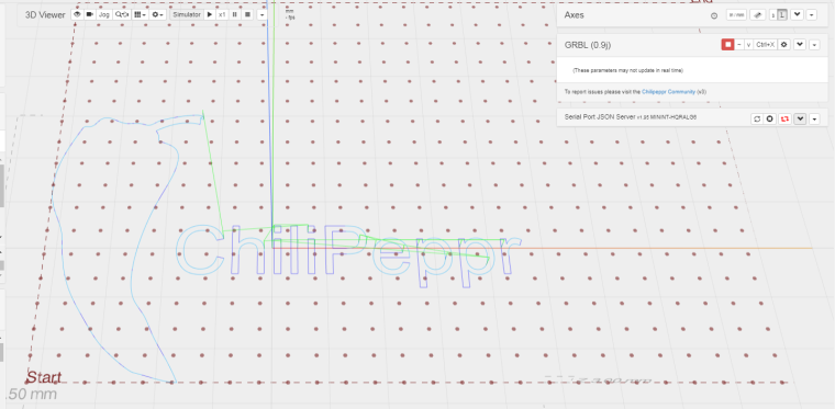
    Otherwise, it runs the risk of not even hitting the PCB if it gets too far out.
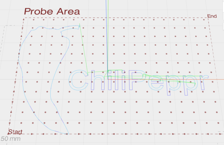

  • Hero Member

    Nailed it!
    0_1513979933006_just_right.png

    Well, further progress will have to wait until I can move the CNC to the garage or outdoors, so that I don't fill the house with toxic fiberglass particles (Thank you @executivul for pointing that out, and sorry I butchered your name earlier. I didn't mean to.)


  • @neverdie no problem, I got used to it since I'm using such a weird nickname, the good part is it's always free to register on any forum so all I have to remember is the pass.

    I'm really excited about wet milling, it's freezing down here and not having to have windows open for the modded vacuum cleaner it's a treat. The trick is to use a solution with higher surface tension then water, but not too thick or it will gather around the mill as a small tornado and start splashing everywhere. You can use soap, shampoo, dishwash, carwash, etc. Start at 1:1 water mix and add more water if it tends to gather around the spinning bit. It's better to pour it slowly on the board and spread with your finger (use a syringe) than to spray it as not to make foam. Also try using a clear shampoo to better see what's milling below the liquid. A piece of flat plastic, acrylic, lexan, plexiglas, whatever, doublesided taped to the wood spoilboard is a must unless you leave a large margin between the actual milling and pcb edge liquid will spill and will swell the wood. Have a roll of paper sheets nearby and a garbage bag open. Always use glasses when operating the machine. I made a "fence" out of some polycarbonate sheet to contain any eventual splashes which occur mostly when drilling through the board, normal engraving behaves and doesn't splash at all.


  • Hero Member

    Given that the goal is to get 6mil isolatioin routing, what cutting depth should I set in flatcam? 0.05mm?


  • @neverdie I have been kind of following this topic, but don't have a CNC mill, but wouldn't the thickness of the copper clad on the board be your depth?


  • Hero Member

    @dbemowsk said in CNC PCB milling:

    @neverdie I have been kind of following this topic, but don't have a CNC mill, but wouldn't the thickness of the copper clad on the board be your depth?

    Makes sense to me. Well, doing that it would be 0.01mm. But since this isn't a perfect process, it likely needs some added depth to guarantee it's removed. The effective tool width gets wider the deeper you cut, so in some sense I suppose there's that as an added constraint on how deep you can cut before it becomes more than 6 mil isolation. We could try to arrive at an answer analytically from first principles only, but I thought it might be easier to just ask what depth others who are doing this successfully are using.


  • @neverdie See what depth you need to go with that bit to get 6 mil routing, and that will be your max. I would think that would be more than 0.01mm, but I haven't seen your bit, so I don't know.


  • @neverdie you should use one depth, regardless of the trace width. for me 0.05mm worked, see my shared settings above. you should decide the isolation width, this is the main property for the given config, but you should stick for one milling depth only. if the requires isolation width is bigger than the tool width at a given depth, then it will use multiple rounds to reach the given width, but still, with one milling depth.


  • Hero Member

    I'm stuck. I converted my gerber to gcode using flatcam, and imported it into Chilipeppr:
    0_1514058048699_stuck.png
    On the one hand, it seems to have gotten the dimensioning right, as indicated by the Y1.48in and X1.43in. However, the grid that it's showing is out of sync with that. Each square on the grid is 5mm. It's as though Chilipeppr thinks the entire design fits easily inside a 5mm square, and so when I attempt to do the autoleveling, it comes out completely wrong.


  • @neverdie said in CNC PCB milling:

    I'm stuck. I converted my gerber to gcode using flatcam, and imported it into Chilipeppr:
    0_1514058048699_stuck.png
    On the one hand, it seems to have gotten the dimensioning right, as indicated by the Y1.48in and X1.43in. However, the grid that it's showing is out of sync with that. Each square on the grid is 5mm. It's as though Chilipeppr thinks the entire design fits easily inside a 5mm square, and so when I attempt to do the autoleveling, it comes out completely wrong.

    you can mark the zero point in the pcb designer tool before you export the gergbel, or in flatcam, during the post processing. if you do not define it, then maybe the given zero point could have some "offset" to the effective design. it is not problem, but it could make your life easier if your zero is e.g. at the pcb's corner.
    if you don't want to update the files, then in chilipeppr you can update the probe area to not start from 0,0 but from a given offset.


  • Hero Member

    Thanks! I don't know why, but somehow that fixed the problem:
    0_1514071420069_gcode2_autolevel.png
    🙂


  • Hero Member

    I found these copper clad boards that seem to be made out of bakelite (?) rather than fiberglass. So, hopefully not the same level of toxic dust concern as with FR4's.

    I double sided taped the non-copper side:
    0_1514073784631_bakelite1.jpg
    and soldered a ground wire on the copper clad side:
    0_1514073810947_bakelite2.jpg

    Now I'm ready for autoleveling and then my first PCB etch.


  • Hero Member

    Here are the results of the autoleveling:
    0_1514079156036_autoleveling.png
    For some reason it's hard to read some of the numbers.


  • @neverdie It looks like everything in the top right corner is above the level bed surface. which puts it above the grid that is shown. Looks like the bed is tilted.


  • Hero Member

    @dbemowsk Fortunately the auto-leveling should render it a moot issue.


  • Hero Member

    LOL, except that unfortunately it did not:
    0_1514080543041_etching1.jpg

    OK, my bad. I hadn't sent the auto-leveled g-code to the workspace (I had thought this would be done automatically, but no), so this picture shows what would happen without auto-leveling.

    I've made the change and am now re-running the job with the auto-leveled g-code.


  • @neverdie Looks about on par with your final matrix, only it is following the grid and not the auto leveling values.


  • Hero Member

    So, I re-ran the job over the same area with the g-code modified by auto-leveling, and this time I got a better result:
    0_1514083159570_etching2.jpg

    So, now I'll try it on a fresh area of the PCB, after doing a new auto-leveling.


  • Hero Member

    Judging from the looks of the photo directly above though, it looks like quite a bit of copper wasn't removed where it needed to be. I'm guessing I will need to:

    1. etch to a deeper depth; and/or,
    2. use a finer mesh for auto-leveling; and/or
    3. ???


  • Etch 0.1mm. The groove between tracks also helps with soldering. I currently use 0.1mm and even 0.15 when in a hurry.


  • @neverdie
    The last photo looks like the tip is missing from the cutter?


  • Hero Member

    @rmtucker Good catch! Here it is in contrast to a new one:
    0_1514124264773_broken.jpg

    I'll replace it with the new one.


  • @neverdie
    Just for future reference i would use a duff cutter for autolevelling then change to a good cutter to cut the job after resetting the z0.
    It is so easy to smash the front of an engraving cutter when using this method for autolevelling as the machine takes a little time to stop after touching the pcb.
    Just my advice anyway☺


  • Hero Member

    @rmtucker said in CNC PCB milling:

    Just for future reference i would use a duff cutter for autolevelling then change to a good cutter to cut the job after resetting the z0.

    What's a "duff cutter"? Did you mean "dull cutter"?


  • @neverdie
    Yes sorry a used one😉


  • Hero Member

    @rmtucker Thanks! Makes sense to me. I'll do it that way.


  • Hero Member

    Argh. I ran the job, and the first cut went great. All subsequent cuts though didn't penetrate the surface:
    0_1514131937250_etch2.jpg
    Afterward, when I checked the zero on z, I found that it was off by 0.049. That explains it, since the cut-depth was 0.05.

    I'll re-zero and try running the same job again.


  • Hero Member

    That made a much better result:
    0_1514134150665_etch3.jpg
    It corresponds to this as the actual PCB:
    0_1514134183073_pcb3.jpg


  • Hero Member

    However, what's telling is that it obliterated the traces on either side of a 6 mil separation:
    0_1514134391307_etch4.jpg
    This is how it should look instead:
    0_1514135454019_jumper.png
    0_1514134628617_pcb4.jpg

    So, what happened?

    My current hypothesis: the first cutting sheared 0.049mm off the tip of the blade, making it wider than it should be. Then, after re-zeroing, the wider blade cut too wide as it cut the traces for the solder jumper.

    Is that reasonable, or is there a better hypothesis?

    If it's true, then what do I do about it? Perhaps use a higher quality bit than the freebie that came with the kit?

    Actually, I'm not even sure what the dimensions were on the freebie. It wasn't labeled. Perhaps it was too wide to begin with.


  • Hero Member

    Well, to explore this more, I think I'll create a test board consisting purely of a few solder jumpers. That way I can put the focus directly on the 6 mil issue and won't be wasting time on etching that's unrelated to that.


  • Hero Member

    Doing just a single solder jumper, with the same bit, and autoleveling every 1mm, the result is:
    0_1514143618998_etch5.jpg
    which is pretty close, actually. Looks like maybe the bit is a little too wide, or else there's runout which is making it appear wider than it actually is.

    I'll try it with a fresh bit next and see if it improves.


  • Hero Member

    Well, that went horribly:
    0_1514145362189_etch6.jpg
    and I have no idea why:


  • Hero Member

    I tried again with the same bit, after removing and re-inserting it. Got a better result this time:
    0_1514147487748_etch7.jpg

    Unless someone has suggestions on how to tweak this, I think that may represent approximately the best this CNC can do.


  • Hero Member

    In truth, though, I think it may be a flawed gcode algorithm:
    0_1514147871026_flawed_algorithm.png
    Instead of two separate cutting passes through the center section, one would do, and would produce a better result.

    How to tweak flatcam to do that? I probably haven't configured flatcam correctly. i.e. user error.


  • @neverdie said in CNC PCB milling:

    Actually, I'm not even sure what the dimensions were on the freebie. It wasn't labeled. Perhaps it was too wide to begin with.

    Maybe this is where your problem lies.
    How did you write the g-code without knowing?
    Too many variables here wich could give you these results.
    The bigger tracks,Are they measuring the correct width with a vernier after you have cut them?


  • Hero Member

    I assumed the width on the freebies was 0.1mm, because that's what was advertised on Jack's posting for the machine. However, I don't know how to verify that, so the uncertainty comes in whether Jack actually delivered what was advertised or slipped in something else. I chose to give Jack the benefit of the doubt.


  • Hero Member

    If I were to enter a wider tool diameter of 0.155mm (instead of 0.1mm) into flatcam, I think I can coax flatcam into generating better g-code for this situation. I'll do that and then post the results.


  • Mod

    @neverdie have you verified isolation between the parts? The cut is good?


  • Hero Member

    No improvement really:
    0_1514155765889_etch8.jpg

    I think this means that the effective cutting width is actually greater than that, either from the bit itself or from runout or from who knows what else.

    Probably nothing I can do about runout, except buy a different/better motor.

    I'll have to wait for the etching bits from Aliexpress to try what is maybe (?) a proper 0.1mm etching bit. Like I say, I have no way of judging whether the freebies that came with the kit really are that or not, as I have nothing to compare.

    By the way, my reason for picking the 0.155mm tool width in flat cam is that it produces this g-code path, which should have preserved more of the copper pad where it was being obliterated:
    0_1514156432764_better-gcode.png


  • Yes you can. Get the gcode I've posted above, adjust for your feedrate, autolevel it in cp and give it a go. Really curious about the results.


  • Hero Member

    @mfalkvidd said in CNC PCB milling:

    @neverdie have you verified isolation between the parts? The cut is good?

    Good question. I have doubts about how well I could measure it using calipers. However, maybe if I put the board onto a flatbed optical scanner, which would have a known DPI, I could measure the actual cut width with reasonable accuracy. I haven't done that yet, though.


  • @NeverDie Using traces one next to other at known distance you can determine the exact width of the engraving for a wanted depth of cut. I know you don't want to mess with gcode, but it's simpler than you think. Please look at the code: you have init (g92 for setting zero, g21 for mm, etc) you set the feedrate in mm/sec, you have a few movements (g0) a "dwell" to pierce the copper for 0.5seconds (g4) then some cutting moves (g1) all have absolute cartesian coordinates. Eg you're at (0,0) then g1 x0y10 means travel at (0,10) move only the y axis 10mm to the back of the machine, g1 x0.1y10 means move 0.1mm to the right, etc.
    You have the whole script posted above, set your feedrate the same as you set in flatcam, and set the depth in the first z-0.1mm line, maybe you want 0.05mm for eg. After editing the file run it in cp with autoleveling and post the results.


  • Hero Member

    @neverdie said in CNC PCB milling:

    @mfalkvidd

    Oh, sorry, I realize now you were asking something else. No, I haven't verified that yet. This is all just early attempts. Good question though.


Log in to reply
 

Suggested Topics

  • 4
  • 1
  • 9
  • 3
  • 2
  • 5

0
Online

11.2k
Users

11.1k
Topics

112.5k
Posts