4CH AC LED Light Dimmer triack Module Leading Edge how to connect with Domoticz using MySensors?
-
Hi,
I'm planning to build controller for light based on Ardino Mega and Domoticz installed on Raspbery Pi 3 B. Somedays ago I 've bought Dimmer for light like here: e-bay dimmer and I'm looking for someone who can help me adopt scetch posted below to control dimming by Domoticz. I am using USB cable ror connection between Arduino and Raspberry at this moment.
Any help appreciated// Testing sketch for 50Hz !!! // / // Dimmer Arduino Mega // | | // GND GND // VCC 5V // SYNC DIGITAL.3 // CH1 DIGITAL.45 // CH2 DIGITAL.47 // CH3 DIGITAL.49 // CH4 DIGITAL.51 //https://github.com/mysensors/MySensorsArduinoExamples/blob/master/examples/RGB_3D/RGB_3D.ino #define MY_DEBUG // Enable debug prints to serial monitor //TO MUSI BYĆ ZDEFINIOWANE PRZED INCLUDE MYSENSORS #define MY_GATEWAY_SERIAL // Enable serial gateway #include <SPI.h> #include <MySensors.h> #include <TimerOne.h> // download this library from arduino.cc #include <Bounce2.h> unsigned char channel_1 = 45; // Output to Opto Triac pin, channel 1 unsigned char channel_2 = 47; // Output to Opto Triac pin, channel 2 unsigned char channel_3 = 49; // Output to Opto Triac pin, channel 3 unsigned char channel_4 = 51; // Output to Opto Triac pin, channel 4 unsigned int CH1, CH2, CH3, CH4; unsigned char i=0; unsigned int delay_time=2500; // delay ms or SPEED unsigned char clock_tick; // variable for Timer1 unsigned char Status_przycisk_1; unsigned char Status_przycisk_2; unsigned char Status_przycisk_3; unsigned char Status_przycisk_4; int16_t last_dim = 33; #define BUTTON_1_PIN 10 #define BUTTON_2_PIN 11 #define BUTTON_3_PIN 12 #define BUTTON_4_PIN 13 Bounce debouncer1 = Bounce(); Bounce debouncer2 = Bounce(); Bounce debouncer3 = Bounce(); Bounce debouncer4 = Bounce(); MyMessage Strefa_1_dimmerMsg(1, V_DIMMER); // Define message name and type to send sensor info MyMessage Strefa_2_dimmerMsg(2, V_DIMMER); MyMessage Strefa_3_dimmerMsg(3, V_DIMMER); MyMessage Strefa_4_dimmerMsg(4, V_DIMMER); void setup() { Serial.begin(9600); pinMode(channel_1, OUTPUT);// Set AC Load pin as output pinMode(channel_2, OUTPUT);// Set AC Load pin as output pinMode(channel_3, OUTPUT);// Set AC Load pin as output pinMode(channel_4, OUTPUT);// Set AC Load pin as output pinMode(BUTTON_1_PIN, INPUT_PULLUP); //przycisk kanał 1 pinMode(BUTTON_2_PIN, INPUT_PULLUP); //przycisk kanał 2 pinMode(BUTTON_3_PIN, INPUT_PULLUP); //przycisk kanał 3 pinMode(BUTTON_4_PIN, INPUT_PULLUP);//przycisk kanał 4 // After setting up the button, setup debouncer. debouncer1.attach(BUTTON_1_PIN); debouncer1.interval(5); debouncer2.attach(BUTTON_2_PIN); debouncer2.interval(5); debouncer3.attach(BUTTON_3_PIN); debouncer3.interval(5); debouncer4.attach(BUTTON_4_PIN); attachInterrupt(1, zero_crosss_int, RISING); Timer1.initialize(100); // set a timer of length 100 microseconds for 50Hz or 83 microseconds for 60Hz; Timer1.attachInterrupt( timerIsr ); // attach the service routine here CH1=CH2=CH3=CH4=99; // WHEN ARDUINO START, ALL LIGHT OFF (95 - FULLY OFF ; 5 - FULLY ON) !!! } void presentation(){ sendSketchInfo("Sciemniacz","1.2"); // Present sketch (name, version) present(1, S_DIMMER, "strefa 1", true); // Register sensors (id, type, description, ack back) present(2, S_DIMMER, "strefa 2", true); present(3, S_DIMMER, "strefa 3", true); present(4, S_DIMMER, "strefa 4", true); } void timerIsr() { clock_tick++; if (CH1==clock_tick){ digitalWrite(channel_1, HIGH); // triac firing delayMicroseconds(10); // triac On propogation delay (for 60Hz use 8.33)\ digitalWrite(channel_1, LOW); // triac Off } if (CH2==clock_tick){ digitalWrite(channel_2, HIGH); // triac firing delayMicroseconds(10); // triac On propogation delay (for 60Hz use 8.33) digitalWrite(channel_2, LOW); // triac Off } if (CH3==clock_tick){ digitalWrite(channel_3, HIGH); // triac firing delayMicroseconds(10); // triac On propogation delay (for 60Hz use 8.33) digitalWrite(channel_3, LOW); // triac Off } if (CH4==clock_tick){ digitalWrite(channel_4, HIGH); // triac firing delayMicroseconds(10); // triac On propogation delay (for 60Hz use 8.33) digitalWrite(channel_4, LOW); // triac Off } } void zero_crosss_int() // function to be fired at the zero crossing to dim the light { // Every zerocrossing interrupt: For 50Hz (1/2 Cycle) => 10ms ; For 60Hz (1/2 Cycle) => 8.33ms // 10ms=10000us , 8.33ms=8330us clock_tick=0; } void loop() { Status_przycisk_1=digitalRead(BUTTON_1_PIN); Status_przycisk_2=digitalRead(BUTTON_2_PIN); Status_przycisk_3=digitalRead(BUTTON_3_PIN); Status_przycisk_4=digitalRead(BUTTON_4_PIN); if (Status_przycisk_1 == 0) { CH1=CH1-1; if (CH1<5){ CH1=99; } } if (Status_przycisk_2 == 0) { CH2=CH2-1; if (CH2<5){ CH2=99; } } if (Status_przycisk_3 == 0) { CH3=CH3-1; if (CH3<5){ CH3=99; } } if (Status_przycisk_4 == 0) { CH4=CH4-1; if (CH4<5){ CH4=99; } } delay(50); }``` -
Hi,
I have try to adopt less complicated version to Domoticz: one button should set value of dimmer to 33 % and second 66%. Unfortunatelly without any success.
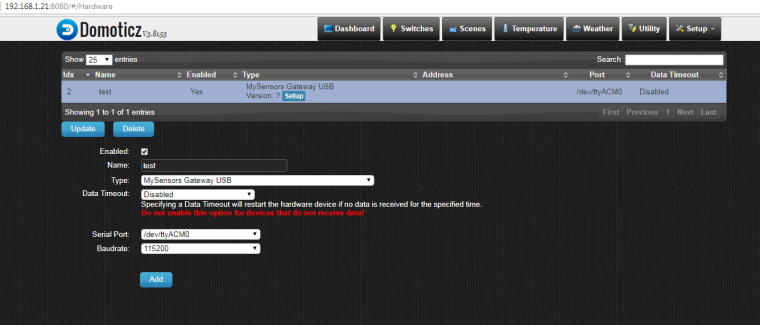
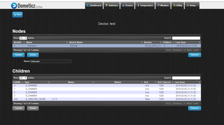
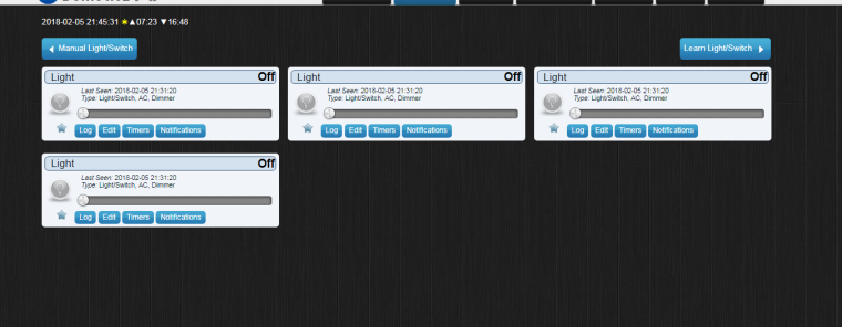
It looks that node is registered with 5 children (I don't know why 5 ).Sketch and some print screens from Domoticz below.
1.
2.
3.
// Testing sketch for 50Hz !
// Dimmer  Arduino
//   |             |
//  GND           GND
//  VCC           5V
//  SYNC        DIGITAL.3
//  CH1         DIGITAL.50
//  CH2         DIGITAL.51
//  CH3         DIGITAL.52
//  CH4         DIGITAL.53
//
//  HC-05       Arduino Mega
//   |             |
//  GND           GND
//  VCC           5V
//  TX            RX (DIGITAL.0)


#define MY_DEBUG  // Enable debug prints to serial monitor
#define MY_GATEWAY_SERIAL // Enable serial gateway
//#define MY_REPEATER_FEATURE
#include <SPI.h>
#include <MySensors.h>
#include <TimerOne.h>    // download this library from arduino.cc
#include <Bounce2.h>
#define BUTTON_1_PIN 4
#define BUTTON_2_PIN 5
#define BUTTON_3_PIN 6
#define BUTTON_4_PIN 7
unsigned char channel_1 = 50; // Output to Opto Triac pin, channel 1
unsigned char channel_2 = 51; // Output to Opto Triac pin, channel 2
unsigned char channel_3 = 52; // Output to Opto Triac pin, channel 3
unsigned char channel_4 = 53; // Output to Opto Triac pin, channel 4
unsigned char Status_button_1;
unsigned char Status_button_2;
unsigned char Status_button_3;
unsigned char Status_button_4;
unsigned char CH1, CH2, CH3, CH4;
unsigned char clock_tick; // variable for Timer1
MyMessage Strefa_1_dimmermsg(0, V_DIMMER);  // Define message name and type to send sensor info
MyMessage Strefa_2_dimmermsg(1, V_DIMMER);
MyMessage Strefa_3_dimmermsg(2, V_DIMMER);
MyMessage Strefa_4_dimmermsg(3, V_DIMMER);
MyMessage Strefa_1_lightmsg(0, V_LIGHT);
MyMessage Strefa_2_lightmsg(1, V_LIGHT);
MyMessage Strefa_3_lightmsg(2, V_LIGHT);
MyMessage Strefa_4_lightmsg(3, V_LIGHT);
Bounce debouncer1 = Bounce();
Bounce debouncer2 = Bounce();
Bounce debouncer3 = Bounce();
Bounce debouncer4 = Bounce();
void setup() {

Serial.begin(9600);
pinMode(channel_1, OUTPUT);// Set AC Load pin as output
pinMode(channel_2, OUTPUT);// Set AC Load pin as output
pinMode(channel_3, OUTPUT);// Set AC Load pin as output
pinMode(channel_4, OUTPUT);// Set AC Load pin as output
pinMode(BUTTON_1_PIN, INPUT_PULLUP); //button channel 1
  pinMode(BUTTON_2_PIN, INPUT_PULLUP); //button channel 2
  pinMode(BUTTON_3_PIN, INPUT_PULLUP); //button channel 3
  pinMode(BUTTON_4_PIN, INPUT_PULLUP);//button channel 4
  // After setting up the button, setup debouncer.
  debouncer1.attach(BUTTON_1_PIN);
  debouncer1.interval(5);
  debouncer2.attach(BUTTON_2_PIN);
  debouncer2.interval(5);
  debouncer3.attach(BUTTON_3_PIN);
  debouncer3.interval(5);
  debouncer4.attach(BUTTON_4_PIN);
attachInterrupt(1, zero_crosss_int, RISING);
Timer1.initialize(75); // set a timer of length 75 microseconds
Timer1.attachInterrupt( timerIsr ); // attach the service routine here

CH1=CH2=CH3=CH4=95; // WHEN ARDUINO START, ALL LIGHT OFF (95 - FULLY OFF ; 5 - FULLY ON) !!!

}
void presentation(){
  sendSketchInfo("Dimmer","05_02_2018_v3");  // Present sketch (name, version)
  for (int sensor=0; sensor<=3;sensor++) // Register all sensors to gw (they will be created as child devices)
  {
    present(sensor, S_DIMMER);}} //Your sensor must first present itself to the controller.
                              //The presentation is a hint to allow controller prepare for the sensor data that eventually will come.
                              // This is done by calling present(child-sensor-id,sensor-type)
                              // Register sensors (id, type, description, ack back)
void timerIsr(){
  clock_tick++;
  if (CH1==clock_tick)
  {
    digitalWrite(channel_1, HIGH); // triac firing
    delayMicroseconds(10); // triac On propogation delay (for 60Hz use 8.33)
    digitalWrite(channel_1, LOW); // triac Off
    }
    if (CH2==clock_tick)
    {
      digitalWrite(channel_2, HIGH); // triac firing
      delayMicroseconds(10); // triac On propogation delay (for 60Hz use 8.33)
      digitalWrite(channel_2, LOW); // triac Off
      }
      if (CH3==clock_tick)
      {
        digitalWrite(channel_3, HIGH); // triac firing
        delayMicroseconds(10); // triac On propogation delay (for 60Hz use 8.33)
        digitalWrite(channel_3, LOW); // triac Off
        }
        if (CH4==clock_tick)
        {
          digitalWrite(channel_4, HIGH); // triac firing
          delayMicroseconds(10); // triac On propogation delay (for 60Hz use 8.33)
          digitalWrite(channel_4, LOW); // triac Off
          }
}
void zero_crosss_int() // function to be fired at the zero crossing to dim the light
{
  // Every zerocrossing interrupt: For 50Hz (1/2 Cycle) => 10ms ; For 60Hz (1/2 Cycle) => 8.33ms
  // 10ms=10000us , 8.33ms=8330us
  clock_tick=0;
  }

void loop() {
Status_button_1=digitalRead(BUTTON_1_PIN);
Status_button_2=digitalRead(BUTTON_2_PIN);

if (Status_button_2==LOW){;
CH1=CH2=CH3=CH4=33;

send(Strefa_1_dimmermsg.set(CH1));
send(Strefa_2_dimmermsg.set(CH2));
send(Strefa_3_dimmermsg.set(CH3));
send(Strefa_4_dimmermsg.set(CH4));
delay(5000);}
if (Status_button_1==LOW){
  CH1=CH2=CH3=CH4=66;

  send(Strefa_1_dimmermsg.set(CH1));
  send(Strefa_2_dimmermsg.set(CH2));
  send(Strefa_3_dimmermsg.set(CH3));
  send(Strefa_4_dimmermsg.set(CH4));
  delay(5000);

}
}
This is what I see in serial port monitor:
(0;0;1;0;3;66
0;1;1;0;3;66
0;2;1;0;3;66
0;3;1;0;3;66
0;0;1;0;3;33
0;1;1;0;3;33
0;2;1;0;3;33
0;3;1;0;3;33) -
Could you plese explain me a little bit more? I'm not sure what are you suggesting.
First I would like to see in domoticz values from Arduino - 33 % or 66% depending on which button I press. -
At the beginning yes, and shortly after I want to control 4 dimmers by Domoticz and by push buttons paralelly.
Second sketch (posted today) it is my testing sketch which I used for learning how communicate with domoticz, but it seems that I have no idea how to doit. -
Hello! It looks like you're interested in this conversation, but you don't have an account yet.
Getting fed up of having to scroll through the same posts each visit? When you register for an account, you'll always come back to exactly where you were before, and choose to be notified of new replies (either via email, or push notification). You'll also be able to save bookmarks and upvote posts to show your appreciation to other community members.
With your input, this post could be even better 💗
Register Login