๐Ÿ’ฌ Roller Shutter Node


  • Hardware Contributor

    Hey, no Problem ๐Ÿ™‚

    I just ask for it, as you write it is in the examples folder ๐Ÿ˜‰

    Thanks for the pre Beta, i will work on it ๐Ÿ‘


  • Hardware Contributor

    @scalz Thanks for the pre beta sketch.
    i have searched the sketch many times in the example folder too ๐Ÿ™‚ But no examples folder find ๐Ÿ˜‰
    I have posted some pictures of the pcb here i fyou want to see:

    http://www.photorapide.com/albums/jordan/khjept/circuit-pcb-roller-shutter-node.html


  • Hardware Contributor

    Hey Scalz, u have forgotten to connect the CSN - Pin in your PCB file for NRF24 ๐Ÿ˜‰ I just solder a bridge between NRF Pin 4 and R14


  • Hardware Contributor

    @takero
    thx for reporting!
    i'm using rfm69, argh. i will take a look asap.


  • Hardware Contributor

    Yah, i know, take it easy this is an minor bug ๐Ÿ™‚
    Your misstake is in the schematic, your wire on the NRF24 CSN-PIN is unnamed.

    For feature Update, it is advisable to plug an ELKO ~400-500uF near the NRF24 Power, i have reciving problems whith "RF24_PA_HIGH" but i need hight for the distance.


  • Hardware Contributor

    @Takero

    But it was named! or the pullup resistor would not be wired, and it was also present on atmel.. and no airwire, weird!
    well, i think it happened during converstion to nrf24.
    Hopefully the pullup resistor is just near the radio!

    Is RF24_PA_HIGH available for nrf24 smd, i thought this was for High power nrf. i'm certainly wrong..I've no problem with rfm though.

    I don't think i will do more, unfortunately, I mean in this case, it's sort of double job, and i'm using rfm69.
    but when i can, i put rfm69 and nrf footprint (i have a pcb not released like this, not a shutter node).

    Now it's updated ๐Ÿ™‚ rev=1.3a for nrf
    See you soon


  • Hardware Contributor

    One question: what are your fuses settings for Optiboot? Dit u use the external 8MHz Clock?
    Can you confirm:

    L: 0xEE
    H: 0xDA
    E: 0x06


  • Hardware Contributor

    @scalz Yes, the resistor is very close ๐Ÿ™‚

    In my .sch the wire is not named ๐Ÿ˜‰ But anyway it works ๐Ÿ‘

    alt text


  • Hardware Contributor

    @Takero

    What the ??
    Are you using Eagle 7x ?? I'm still using 6.5..when it works i don't change if no need ๐Ÿ˜‰
    but dooo! In my version i see the signal..i think this is sort of very exotic bug case and i got in my face lol
    0_1476951269074_2016-10-20_10-13-29.jpg
    Weird, hein !
    no matter thx for reporting, good to know i'll remember or update, we learn from our errors as we say ๐Ÿ™‚


  • Hardware Contributor

    @scalz
    Yes 7.5. Hey it was an "easy to solve" problem ๐Ÿ˜„

    . . . maybe an eagle bug


  • Hardware Contributor

    easy to solve when you've eagle 7.5 ahah

    For fuse&bootloader, you can use OTA howto, that's the same : https://www.mysensors.org/about/ota


  • Hardware Contributor

    @scalz Are you sure about the Fuses? 0xE2 is normal for int. clock?! Or i am wrong?

    http://eleccelerator.com/fusecalc/fusecalc.php?chip=atmega328p&LOW=E2&HIGH=DA&EXTENDED=06&LOCKBIT=FF


  • Hardware Contributor

    yes this ok, i'm using this for most of my nodes.
    And your link shows that it sets internal rc.


  • Hardware Contributor

    Ok, Thanks


  • Hardware Contributor

    Hey Scalz,

    my prototype of your RollerShutter works well right now. I have add an Capacitor (470uF) near the NRF (it is realy needed! otherwise OTA CRC Fail, lost packages)

    I have a litte bit trouble with the Current Sensor or the calculation of this.
    I Used 2 60W Bulbs, if i PressDown or UP the Power Value increase up to 350W and need a loooooooonng time to decrease. round about 1W per sec.

    Is this normal? In my opinion not but maybe my ASC is defective? I use a modification of your pre-alpha Sketch


  • Hardware Contributor

    hmm. i didn't have 1w/sec.. perhaps acs.. i've already got a few defective. i'll check a bit when i'll have more time, too much cooking.
    In case you can set default define duration, and this works well then.
    But looks you got it! Great to hear it though ๐Ÿ™‚


  • Hardware Contributor

    Yaah dont hurry ๐Ÿ˜„

    here is the log:

     [2016-11-01 10:49:04.702 Info] RX	0;255;3;0;9;TSP:MSG:READ 50-50-0 s=6,c=1,t=17,pt=3,l=2,sg=0:465
     [2016-11-01 10:49:04.727 Info] RX	50;6;1;0;17;465
     [2016-11-01 10:49:04.728 Info] RX	0;255;3;0;9;TSP:MSG:READ 50-50-0 s=6,c=1,t=17,pt=3,l=2,sg=0:466
     [2016-11-01 10:49:04.728 Info] RX	50;6;1;0;17;466
     [2016-11-01 10:49:14.731 Info] RX	0;255;3;0;9;TSP:SANCHK:OK
     [2016-11-01 10:49:28.130 Info] RX	0;255;3;0;9;TSP:MSG:READ 50-50-0 s=6,c=1,t=17,pt=3,l=2,sg=0:445
     [2016-11-01 10:49:28.137 Info] RX	50;6;1;0;17;445
     [2016-11-01 10:49:28.265 Info] RX	0;255;3;0;9;TSP:MSG:READ 50-50-0 s=6,c=1,t=17,pt=3,l=2,sg=0:446
     [2016-11-01 10:49:28.267 Info] RX	50;6;1;0;17;446
     [2016-11-01 10:49:54.722 Info] RX	0;255;3;0;9;TSP:MSG:READ 50-50-0 s=6,c=1,t=17,pt=3,l=2,sg=0:425
     [2016-11-01 10:49:54.727 Info] RX	50;6;1;0;17;425
     [2016-11-01 10:49:54.787 Info] RX	0;255;3;0;9;TSP:MSG:READ 50-50-0 s=6,c=1,t=17,pt=3,l=2,sg=0:426
     [2016-11-01 10:49:54.788 Info] RX	50;6;1;0;17;426
     [2016-11-01 10:50:14.760 Info] RX	0;255;3;0;9;TSP:SANCHK:OK
     [2016-11-01 10:50:23.029 Info] RX	0;255;3;0;9;TSP:MSG:READ 50-50-0 s=6,c=1,t=17,pt=3,l=2,sg=0:405
     [2016-11-01 10:50:23.032 Info] RX	50;6;1;0;17;405
     [2016-11-01 10:50:23.054 Info] RX	0;255;3;0;9;TSP:MSG:READ 50-50-0 s=6,c=1,t=17,pt=3,l=2,sg=0:406
     [2016-11-01 10:50:23.055 Info] RX	50;6;1;0;17;406
     [2016-11-01 10:50:53.223 Info] RX	0;255;3;0;9;TSP:MSG:READ 50-50-0 s=6,c=1,t=17,pt=3,l=2,sg=0:385
     [2016-11-01 10:50:53.226 Info] RX	50;6;1;0;17;385
     [2016-11-01 10:50:53.261 Info] RX	0;255;3;0;9;TSP:MSG:READ 50-50-0 s=6,c=1,t=17,pt=3,l=2,sg=0:386
     [2016-11-01 10:50:53.262 Info] RX	50;6;1;0;17;386
     [2016-11-01 10:51:14.788 Info] RX	0;255;3;0;9;TSP:SANCHK:OK
     [2016-11-01 10:51:25.712 Info] RX	0;255;3;0;9;TSP:MSG:READ 50-50-0 s=6,c=1,t=17,pt=3,l=2,sg=0:365
     [2016-11-01 10:51:25.718 Info] RX	50;6;1;0;17;365
     [2016-11-01 10:51:25.725 Info] RX	0;255;3;0;9;TSP:MSG:READ 50-50-0 s=6,c=1,t=17,pt=3,l=2,sg=0:366
     [2016-11-01 10:51:25.732 Info] RX	50;6;1;0;17;366
     [2016-11-01 10:51:59.985 Info] RX	0;255;3;0;9;TSP:MSG:READ 50-50-0 s=6,c=1,t=17,pt=3,l=2,sg=0:345
     [2016-11-01 10:51:59.989 Info] RX	50;6;1;0;17;345
     [2016-11-01 10:52:00.013 Info] RX	0;255;3;0;9;TSP:MSG:READ 50-50-0 s=6,c=1,t=17,pt=3,l=2,sg=0:346
     [2016-11-01 10:52:00.014 Info] RX	50;6;1;0;17;346
     [2016-11-01 10:52:14.818 Info] RX	0;255;3;0;9;TSP:SANCHK:OK
     [2016-11-01 10:52:36.088 Info] RX	0;255;3;0;9;TSP:MSG:READ 50-50-0 s=6,c=1,t=17,pt=3,l=2,sg=0:325
     [2016-11-01 10:52:36.091 Info] RX	50;6;1;0;17;325
     [2016-11-01 10:52:36.117 Info] RX	0;255;3;0;9;TSP:MSG:READ 50-50-0 s=6,c=1,t=17,pt=3,l=2,sg=0:326
     [2016-11-01 10:52:36.119 Info] RX	50;6;1;0;17;326
     [2016-11-01 10:53:14.248 Info] RX	0;255;3;0;9;TSP:MSG:READ 50-50-0 s=6,c=1,t=17,pt=3,l=2,sg=0:305
     [2016-11-01 10:53:14.251 Info] RX	50;6;1;0;17;305
     [2016-11-01 10:53:14.278 Info] RX	0;255;3;0;9;TSP:MSG:READ 50-50-0 s=6,c=1,t=17,pt=3,l=2,sg=0:306
     [2016-11-01 10:53:14.279 Info] RX	50;6;1;0;17;306
     [2016-11-01 10:53:14.848 Info] RX	0;255;3;0;9;TSP:SANCHK:OK
     [2016-11-01 10:53:54.586 Info] RX	0;255;3;0;9;TSP:MSG:READ 50-50-0 s=6,c=1,t=17,pt=3,l=2,sg=0:285
     [2016-11-01 10:53:54.590 Info] RX	50;6;1;0;17;285
     [2016-11-01 10:53:54.613 Info] RX	0;255;3;0;9;TSP:MSG:READ 50-50-0 s=6,c=1,t=17,pt=3,l=2,sg=0:286
     [2016-11-01 10:53:54.614 Info] RX	50;6;1;0;17;286
     [2016-11-01 10:54:14.876 Info] RX	0;255;3;0;9;TSP:SANCHK:OK
     [2016-11-01 10:54:36.813 Info] RX	0;255;3;0;9;TSP:MSG:READ 50-50-0 s=6,c=1,t=17,pt=3,l=2,sg=0:265
     [2016-11-01 10:54:36.817 Info] RX	50;6;1;0;17;265
     [2016-11-01 10:54:36.843 Info] RX	0;255;3;0;9;TSP:MSG:READ 50-50-0 s=6,c=1,t=17,pt=3,l=2,sg=0:266
     [2016-11-01 10:54:36.845 Info] RX	50;6;1;0;17;266
     [2016-11-01 10:55:14.904 Info] RX	0;255;3;0;9;TSP:SANCHK:OK
     [2016-11-01 10:55:21.198 Info] RX	0;255;3;0;9;TSP:MSG:READ 50-50-0 s=6,c=1,t=17,pt=3,l=2,sg=0:245
     [2016-11-01 10:55:21.202 Info] RX	50;6;1;0;17;245
     [2016-11-01 10:55:21.223 Info] RX	0;255;3;0;9;TSP:MSG:READ 50-50-0 s=6,c=1,t=17,pt=3,l=2,sg=0:246
     [2016-11-01 10:55:21.224 Info] RX	50;6;1;0;17;246
     [2016-11-01 10:56:08.275 Info] RX	0;255;3;0;9;TSP:MSG:READ 50-50-0 s=6,c=1,t=17,pt=3,l=2,sg=0:225
     [2016-11-01 10:56:08.278 Info] RX	50;6;1;0;17;225
     [2016-11-01 10:56:08.304 Info] RX	0;255;3;0;9;TSP:MSG:READ 50-50-0 s=6,c=1,t=17,pt=3,l=2,sg=0:226
     [2016-11-01 10:56:08.306 Info] RX	50;6;1;0;17;226
     [2016-11-01 10:56:14.934 Info] RX	0;255;3;0;9;TSP:SANCHK:OK
     [2016-11-01 10:56:58.403 Info] RX	0;255;3;0;9;TSP:MSG:READ 50-50-0 s=6,c=1,t=17,pt=3,l=2,sg=0:205
     [2016-11-01 10:56:58.406 Info] RX	50;6;1;0;17;205
     [2016-11-01 10:56:58.432 Info] RX	0;255;3;0;9;TSP:MSG:READ 50-50-0 s=6,c=1,t=17,pt=3,l=2,sg=0:206
     [2016-11-01 10:56:58.434 Info] RX	50;6;1;0;17;206
     [2016-11-01 10:57:14.963 Info] RX	0;255;3;0;9;TSP:SANCHK:OK
     [2016-11-01 10:57:51.378 Info] RX	0;255;3;0;9;TSP:MSG:READ 50-50-0 s=6,c=1,t=17,pt=3,l=2,sg=0:185
     [2016-11-01 10:57:51.381 Info] RX	50;6;1;0;17;185
     [2016-11-01 10:57:51.403 Info] RX	0;255;3;0;9;TSP:MSG:READ 50-50-0 s=6,c=1,t=17,pt=3,l=2,sg=0:186
     [2016-11-01 10:57:51.404 Info] RX	50;6;1;0;17;186
     [2016-11-01 10:58:14.991 Info] RX	0;255;3;0;9;TSP:SANCHK:OK
     [2016-11-01 10:58:47.254 Info] RX	0;255;3;0;9;TSP:MSG:READ 50-50-0 s=6,c=1,t=17,pt=3,l=2,sg=0:165
     [2016-11-01 10:58:47.280 Info] RX	50;6;1;0;17;165
     [2016-11-01 10:58:47.281 Info] RX	0;255;3;0;9;TSP:MSG:READ 50-50-0 s=6,c=1,t=17,pt=3,l=2,sg=0:166
     [2016-11-01 10:58:47.282 Info] RX	50;6;1;0;17;166
     [2016-11-01 10:59:15.019 Info] RX	0;255;3;0;9;TSP:SANCHK:OK
     [2016-11-01 10:59:46.972 Info] RX	0;255;3;0;9;TSP:MSG:READ 50-50-0 s=6,c=1,t=17,pt=3,l=2,sg=0:145
     [2016-11-01 10:59:46.977 Info] RX	50;6;1;0;17;145
     [2016-11-01 10:59:47.040 Info] RX	0;255;3;0;9;TSP:MSG:READ 50-50-0 s=6,c=1,t=17,pt=3,l=2,sg=0:146
     [2016-11-01 10:59:47.041 Info] RX	50;6;1;0;17;146
     [2016-11-01 11:00:15.047 Info] RX	0;255;3;0;9;TSP:SANCHK:OK
     [2016-11-01 11:00:52.176 Info] RX	0;255;3;0;9;TSP:MSG:READ 50-50-0 s=6,c=1,t=17,pt=3,l=2,sg=0:125
     [2016-11-01 11:00:52.181 Info] RX	50;6;1;0;17;125
     [2016-11-01 11:00:52.244 Info] RX	0;255;3;0;9;TSP:MSG:READ 50-50-0 s=6,c=1,t=17,pt=3,l=2,sg=0:126
     [2016-11-01 11:00:52.245 Info] RX	50;6;1;0;17;126
     [2016-11-01 11:01:15.076 Info] RX	0;255;3;0;9;TSP:SANCHK:OK
     [2016-11-01 11:02:08.445 Info] RX	0;255;3;0;9;TSP:MSG:READ 50-50-0 s=6,c=1,t=17,pt=3,l=2,sg=0:105
     [2016-11-01 11:02:08.449 Info] RX	50;6;1;0;17;105
     [2016-11-01 11:02:08.505 Info] RX	0;255;3;0;9;TSP:MSG:READ 50-50-0 s=6,c=1,t=17,pt=3,l=2,sg=0:106
     [2016-11-01 11:02:08.506 Info] RX	50;6;1;0;17;106
    

    Bootup Log:

    57	01.11.2016 12:34:04	TX	50	50		0	6	C_SET	V_WATT	UINT16	2	NO		62
    59	01.11.2016 12:34:05	TX	50	50		0	6	C_SET	V_WATT	UINT16	2	NO		63
    61	01.11.2016 12:34:05	TX	50	50		0	6	C_SET	V_WATT	UINT16	2	NO		64
    63	01.11.2016 12:34:06	TX	50	50		0	6	C_SET	V_WATT	UINT16	2	NO		65
    65	01.11.2016 12:34:07	TX	50	50		0	6	C_SET	V_WATT	UINT16	2	NO		66
    67	01.11.2016 12:34:08	TX	50	50		0	3	C_SET	V_TEMP	BYTE	1	NO		25
    69	01.11.2016 12:34:08	TX	0	0	50	50	3	C_SET	V_TEMP	BYTE	1	NO	ok	25
    71	01.11.2016 12:34:08	TX	50	50		0	6	C_SET	V_WATT	UINT16	2	NO		67
    73	01.11.2016 12:34:09	TX	50	50		0	6	C_SET	V_WATT	UINT16	2	NO		68
    75	01.11.2016 12:34:10	TX	50	50		0	6	C_SET	V_WATT	UINT16	2	NO		69
    77	01.11.2016 12:34:11	TX	50	50		0	6	C_SET	V_WATT	UINT16	2	NO		70
    79	01.11.2016 12:34:12	TX	50	50		0	6	C_SET	V_WATT	UINT16	2	NO		71
    81	01.11.2016 12:34:14	TX	50	50		0	6	C_SET	V_WATT	UINT16	2	NO		72
    83	01.11.2016 12:34:15	TX	50	50		0	6	C_SET	V_WATT	UINT16	2	NO		73
    85	01.11.2016 12:34:17	TX	50	50		0	6	C_SET	V_WATT	UINT16	2	NO		74
    87	01.11.2016 12:34:19	TX	50	50		0	6	C_SET	V_WATT	UINT16	2	NO		75
    89	01.11.2016 12:34:21	TX	50	50		0	6	C_SET	V_WATT	UINT16	2	NO		76
    91	01.11.2016 12:34:24	TX	50	50		0	6	C_SET	V_WATT	UINT16	2	NO		77
    93	01.11.2016 12:34:26	TX	50	50		0	6	C_SET	V_WATT	UINT16	2	NO		78
    95	01.11.2016 12:34:30	TX	50	50		0	6	C_SET	V_WATT	UINT16	2	NO		79
    97	01.11.2016 12:34:33	TX	50	50		0	6	C_SET	V_WATT	UINT16	2	NO		80
    99	01.11.2016 12:34:38	TX	50	50		0	6	C_SET	V_WATT	UINT16	2	NO		81
    101	01.11.2016 12:34:43	TX	50	50		0	6	C_SET	V_WATT	UINT16	2	NO		82
    103	01.11.2016 12:34:50	TX	50	50		0	6	C_SET	V_WATT	UINT16	2	NO		83
    106	01.11.2016 12:34:59	TX	50	50		0	6	C_SET	V_WATT	UINT16	2	NO		84
    108	01.11.2016 12:35:10	TX	50	50		0	6	C_SET	V_WATT	UINT16	2	NO		85
    110	01.11.2016 12:35:23	TX	50	50		0	6	C_SET	V_WATT	UINT16	2	NO		86


  • Hardware Contributor

    It is possible that you dont use the asc for the autocalibration yet? I cant find it in your Code .... I found only the read process.

    Corect me if i am wrong. ๐Ÿ™‚


  • Hardware Contributor

    acs read can set an endstop bool = "event" which trig the shutter state machine. you should see it ๐Ÿ˜‰
    in case you have some trouble, then you can set few default define in sketch to set your travel time. perhaps a cleareeprom needed, then shutter should be ready.


  • Hardware Contributor

    @scalz

    Yes, i work on it . . . still my ACS wont work well. At the moment i init the node with the Endstop Bool, that works fine.

    I work also on an delay between the UP/DOWN States, i don't like it if the shutter change the direktion directly. But . . . not find the right way yet ๐Ÿ™‚

    EDIT: ACS works right now!!! ๐Ÿ‘ I think my IC was defective ๐Ÿ‘Ž


  • Hardware Contributor

    Dont know why but while autocali. they stop messurement of current . . .

    If i start the process the first is go UP, my messurment of power is: 30W
    if i Power of the attached Bulb the value stays on 30W, so it is normal he cant detect anythink

    In your loop:

     // Read current sensor, endstop
      uint16_t acsread = 0;  
      acsread = readAdcWithFilter(ACS712_SENSOR, PS_64); 
      if (acsread < ACS712_LEVELDETECT) {
          // Endstop detected  
          if (getCalibrationState() > 0) setEndStopState(true); 
          else {};
      }
    

    I modified for debug like this:

    // Read current sensor, endstop
      uint16_t acsread = 0;  
      acsread = readAdcWithFilter(ACS712_SENSOR, PS_64); 
    
    
      Serial.print(F("ACS712: READ DEBUG: ")); 
      Serial.println(acsread);
    
    
      if (acsread < ACS712_LEVELDETECT) {
          // Endstop detected  
          if (getCalibrationState() > 0) setEndStopState(true); 
          else {};
      }
    

    It never change the value of acsread after the init process is started. . .

    LOG:

    TSP:MSG:READ 0-0-50 s=2,c=1,t=2,pt=0,l=1,sg=1:1
    CMD: Autocalibration
    ACS712: READ DEBUG: 7
    ACS712: READ DEBUG: 29
    ACS712: READ: 29
    TSP:MSG:SEND 50-50-0-0 s=6,c=1,t=17,pt=3,l=2,sg=0,ft=0,st=ok:29
    ACS712: READ DEBUG: 29
    ACS712: READ DEBUG: 29
    ACS712: READ DEBUG: 29
    ACS712: READ DEBUG: 29
    ACS712: READ DEBUG: 29
    ACS712: READ DEBUG: 29
    ACS712: READ DEBUG: 29
    ACS712: READ DEBUG: 29
    ACS712: READ DEBUG: 29
    ACS712: READ DEBUG: 29
    ACS712: READ DEBUG: 29
    ACS712: READ DEBUG: 29
    ACS712: READ DEBUG: 29
    ACS712: READ DEBUG: 29
    ACS712: READ DEBUG: 29
    ACS712: READ DEBUG: 29
    ACS712: READ DEBUG: 29
    ACS712: READ DEBUG: 29
    ACS712: READ DEBUG: 29
    ACS712: READ DEBUG: 29
    ACS712: READ DEBUG: 29
    ACS712: READ DEBUG: 29
    ACS712: READ DEBUG: 29
    ACS712: READ DEBUG: 29
    ACS712: READ DEBUG: 29
    ACS712: READ DEBUG: 29
    ACS712: READ DEBUG: 29
    ACS712: READ DEBUG: 29
    ACS712: READ DEBUG: 29
    ACS712: READ DEBUG: 29
    ACS712: READ DEBUG: 29
    

    29 will stay until timout stop. . . between this i power of the attached test bulb (20W)


  • Hardware Contributor

    Level detection work right now . . .

    my modifications:

    // send % progression for controller widgets NOT TESTED  
      static uint8_t oldpos = getPosition();
      
      if (oldpos != getPosition() && getCalibrationState()==0) {
        send(msgShutterPosition.set(getPosition()));
        send(msgPercent.set(getPosition()));
        oldpos = getPosition();
      } 
    

  • Hardware Contributor

    I am finished and everythink is working well right now.

    I dit some modifications on PCB:

    • add an 470uF near to NRF24
    • add two Diodes recovery diode (or free-wheeling diode) dunno how it called in english ๐Ÿ™‚ at the relays

    And some changes in your example code ๐Ÿ‘

    Thanks for the Layout, thanks for the code, thanks for help!

    I design a 3D Case, but only the bottom side. . . but not tested right now . .

    alt text

    0_1478263225360_RollerShutter_back.stl
    0_1478263256093_RollerShutter_Back.123dx


  • Did you try ACS measurement for up AND down ? On my 2 boards, i have problem with relay just over ACS and errors in current measurment (magnetic field of relay just over Hall sensor)
    @scalz : I think we could try to turn 90ยฐ acs712, it could be fine.


  • Hardware Contributor

    With a Little Bit Trouble yes. The Problem is the Dimension of the amplifier. Below 60W the messured voltage is to Low.

    I think it is netter the Diode must be in the Feedback cycle of the amplifier. But in my case the Free running voltage is below 6 and with running Roller above 20. So it is possible to detect the End stops. Just modify the variables.

    I will Test it in the"real" System tomorow. If it Works i will post the Sketch.


  • Hardware Contributor

    @Fabien
    i will take a look asap.. i'm actually playing with my nano32, and some design ๐Ÿ˜‰
    perhaps for the atsam version when more time to release..

    @Takero
    thx for feedback ๐Ÿ‘

    • i'll look to your suggestions too. for the wheeling diode if i remember it's integrated in the relay driver. depends what you mean.
    • For sketch, hehe, i warned it was not complete ๐Ÿ™‚ but the most important there. I'll look at your change and update it, sure !i have actually no time to play with it, still using an old sketch.

    too much coding to do, and hardware to play! but this is so fun ๐Ÿ™‚

    see you soon


  • Hardware Contributor

    @scalz said:

    for the wheeling diode if i remember it's integrated in the relay driver. depends what you mean

    It isn't ๐Ÿ™‚


  • Hardware Contributor

    well, it is a zener, not wheeling diode, which should be enough..
    http://www.onsemi.com/pub_link/Collateral/MDC3105-D.PDF
    perhaps not for nrf! cool if it improves.

    sidenote: i won't change nrf version in future. as i only have rfm69 (doing nrf was bonus), i don't want to waste my time improving both! and i have enough pcb ahah


  • Hardware Contributor

    Dont Care ๐Ÿ™‚ its cool. Zenner its not enoth but dont worry. I need it .. the nrf is verry "female" ๐Ÿ˜„ (sensible). But i think for both version, you have to modify the current messurment. No Roller shutter has >200w so u are on the Limit below 100w of adc scale.

    But hey it Works and your Layout is verry cool and Safe.


  • Very stange. Zener in forward side is equivalent to classical diode.
    @Takero, you change the amplifier ? Wich mods did you make ?


  • Hardware Contributor

    I was a little bit bussy the last days.
    My Nodes are completed installed right now, it works well. BUT, i had to change some thinks.

    I had the Probleme of automatic reset of the device if i set the shutter to 50% or anythink else 0% or 100%.
    The Diode alone dont solve these Probleme. I think the Problem is to stop the shutter while running. If i set it to 100% or 0% the shutter shut of before the relay falls down.

    I solve the Problem with a 220uF Capacitor at the 3.3V Out and deactivate the BOD.

    My Fuses right now: L: CF // H:DA // E:07

    Now it works very well!!

    @Fabien: I dont change the amp . . i just tested some thinks but it wont work . . for i dont use the current messurment and setup the Node with the manual endstop. It works realy good!

    Finaly again, Thanks @scalz

    The Temp. of the devices is below 30ยฐC ๐Ÿ˜‰

    In the picture the green temp.

    0_1481916187089_Unbenannt.JPG


  • Hi
    I was wondering if the ACS712 can detect the current if the roller shutter power is 85W?


  • Hi, there is something similar available although without an ac712. So you can't check the percentage o the shutter.
    See https://github.com/JanGoe/esp8266-wifi-relay
    I had one at home and it is working well. Because of the esp8266 it is directly connected to any controller using udp or MQTT or other protocols.
    The only problem is the missing box. I have to admit I wouldn't put this in my wall without a proper box using AC 240 V!!!
    The project you proposed is of course the most advanced. Do you think there is a smaller version available perhaps less parts on the BOM and easy to build?
    Thank you very much, kduino


  • Cloudy/rainning day ... Good for MySensors
    0_1491138689145_IMG_20170402_145718.jpg


  • There is a mistake on the above photo. Radios are on the wrong way (180ยฐ)


  • @scalz, little mistake on BOM, C4 is 100n AND 10n ..


  • Hi, I make this project, pretty cool.

    How I can upload the firmware? What I need to do?


  • Hardware Contributor

    @Sergio-Rodrigues
    It's better to talk about this here instead of private, so other people can learn or help you ๐Ÿ˜‰

    it's "like" programming an arduino board.

    1. in arduino ide, program bootloader (for these, i used the sensebender board in Board manager).
    2. Then, with a FTDI adapter, program the rollershutter sketch.

    For more infos on programming arduino:

    What do you need to know exactly ??


  • Finnaly I find a solution with a very good WAF !
    I want to keep a sort of manual command (not gateway or controller dependant) and I don't want an expensive solution (my ODACE schneider button are quite expensive and I don't want to buy other button).
    But these button measure 38mm depth and @scalz board is about 20mm. My wall boxes are 50mm !
    Si I find some special wall boxes with an enclosure for home automation module. It's cheap (about 3โ‚ฌ) and very well designed (french RT2012 compliant). I update the sketch with MY_TRANSPORT_WAIT_READY_MS so node can work alone. And I update sketch to work with bistable button. Works well on 2 windows since yesterday.
    Here is a photo before :
    0_1505166550880_IMG_20170911_233746.jpg


  • Admin

    Almost looks like this type type of part-rubber box that can be mounted without tearing down the wall:
    0_1505167914932_1426270.jpg

    https://www.eldirekt.se/elmaterial/elinstallation/infallda-dosor/multidosa-big-box

    SE - Multidosa โ€“ 00:35
    โ€” Gycom


  • Some other photos (sorry, first one is not in the same room) :
    0_1505251878615_IMG_20170912_174015.jpg
    0_1505251889179_IMG_20170912_110933.jpg
    0_1505251895779_IMG_20170912_111143.jpg
    0_1505251903528_IMG_20170912_111331.jpg


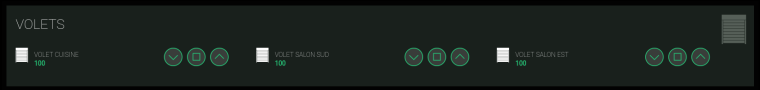
  • One test screenshot (not definitive) of my habpanel (openHab 2.0 part).
    I'm using OpenHAB mysensors binding (from @TimO), node-red for rules, habpanel for UI, Tasker on android (for example open all RollerShuter just after morning alarm !).
    I can access OpenHAB via nginx reverse proxy with https and on my LAN, home automation have a separate VLAN (for security reasons). Thanks a lot to @scalz for this module.
    0_1505252614465_Capture du 2017-09-12 23-36-35.png


  • Hardware Contributor

    @scalz great work, sorry to dig up the topic, but good topics never die ( ๐Ÿ™‚ ). Can you clarify some questions?

    • Way did you used 2 different relays? Way not only one type?
    • What is the Amp consumption of your motors? I know that 10A is overkill, but just to get one idea. Would 2A do it? (at 220V)
    • I see that you added a 8Mhz Cristal, way not use the internal clock? It's 8Mhz
    • I see that you use a relay driver, correct me if I'm wrong, that is because the rated coil consumption to those relays is 80mA.

    Thank You
    Great Work


  • @Soloam
    2 relay for interlocking system and add more security.
    I never mesure my current but it's low ... not 10A !
    Internal clock is not very precise and can vary with external parameters like temperature. And for this project it's better to have good precision.
    It's always better to use relay driver and not directly arduino pin.


  • Hardware Contributor

    @fabien said in ๐Ÿ’ฌ Roller Shutter Node:

    @Soloam
    2 relay for interlocking system and add more security.
    I never mesure my current but it's low ... not 10A !
    Internal clock is not very precise and can vary with external parameters like temperature. And for this project it's better to have good precision.
    It's always better to use relay driver and not directly arduino pin.

    Thank you @Fabien all very clarifying, only one thing that I don't understand (sorry, but I like to use this projects to learn and improve my personal knowledge) I still don't understand way the relays are different model numbers, from what I can see, one is 4 pins, and the other 5 pins, or I'm miss interpreting?

    Thank you


  • Mod

    one relay only needs to be on/off while the other needs to select between up and down motion.


  • Hardware Contributor

    @Soloam
    about relays, imagine there would be two same relays:

    • two SPDT would not make sense here, plus it would add more pins.

    • two SPST wouldn't be secure, there could be a moment where you could have both relays activated (for example in case pins are not well set on startup, or of bad sketch). That would not be great for motor.
      So there is one (SPST) to enable power flowing to the SPDT which toggle between UP or DOWN.

    • there are parts on my schematic which could be optional. I always put as much footprints as I can, for reference, and especially when I need to fix something it's handy.
      Sure crystal could be optional, and you could burn sensebender bootloader for example, or like fabien said it's good to have. It's an AC powered node, so not really needed to try saving something. And also, if you're paranoid about sourcing cheap, and why not out of specs, atmel on aliexpress, then you have the footprints available.

    • the relay driver is nice because it helps protecting atmel and improve reliability. It integrates all parts for relays in one package (transistors, diodes, resistors etc.) so it simplifies schematic and takes less place on pcb too.

    • 10amp omron relays, better oversize, so you're sure they won't suffer ๐Ÿ™‚ and the board can be used for other stuff needing more power than rollershutters in case.


  • Hardware Contributor

    @scalz this is a great work, I'm planning on ordering a couple to use on my system.

    Besides that, I'm most interested in the integrated Current Sensor, and planning on use it on my one PCB. I've been studding your PCB layout and reading regarding the ACS712 and is integration with the LM321. Way didn't you use the schematic on the ACS712 DataSheet (http://henrysbench.capnfatz.com/henrys-bench/arduino-current-measurements/acs712-current-sensor-user-manual/ page 12) to integrate with the LM321? I see that you use a lot more resistors and caps, and the values are not the same. Was this intencional or you did it to reuse a footprint? Would the layout on the DataSheet also work in you board? (From what I can tell it changes the sensitivity).

    Also I see a couple 0 Ohm resistor, I think that that is to reuse footprints correct?

    Thank you for your help and contribute to the community.


  • Hardware Contributor

    @Soloam
    Your link is about DC. He has another howto for AC, which is based on sampling adc but i was not interested in this one. I didn't want the current measurement dependant on sampling reliability and misses.
    So I used part of datasheet schematic, and I adjusted it to my application. If you use it in another projects, you may need to adjust resistor divider etc.
    0ohms needs to be soldered.


  • Hi,

    I have been searching for a longtime for some decent rollershutter solution. I have about 12 of them and i am currently using a sonoff relay solution which works but i never really know the position if it is open or closed or pourcentage position.

    What your solution seems to do.

    Is it possible to interface this with amazon echo or google home to ask to open/close the shutter but also ask the status. Are my shutters open or closed? Or open window shutter 1 at 50%?

    Also there is a link to purchase 10 pcb at 21$ is the the complete solution (plug &play, including relays, connectors,,,) or is it just the board and do i need to solder everything my self?

    Thank you and great job at doing this! ๐Ÿ™‚


  • Mod

    You still need to get parts and solder everything together.


  • Hi,

    Where could i buy a finished version of this hardware?


  • @hitech2207 I do not think it is for sale as a finished product.
    You still have to get everything assembled as @gohan had.

    EDIT: re amazon echo or any other control can be done from RPi hosting a controller.


  • Hello, nice Node! How to order a NRF Version? If i click buy, i have no choice.


  • Hardware Contributor

    I'm having difficult finding the IC4 ACS712_5A, if I search for "ACS712 5A" I only get the assembled unit. Can I get one of this and unsolder the IC and use it?


  • @soloam said in ๐Ÿ’ฌ Roller Shutter Node:

    I'm having difficult finding the IC4 ACS712_5A, if I search for "ACS712 5A" I only get the assembled unit. Can I get one of this and unsolder the IC and use it?

    ali

    https://ru.aliexpress.com/item/ACS712-ACS712ELCTR-05B-ACS712TELC-05B/32789439410.html
    https://ru.aliexpress.com/item/-/32875918012.html
    https://ru.aliexpress.com/item/2-ACS712ELCTR-05B-T-ACS712T-SOP8-ACS712-SMD/32846519263.html
    https://ru.aliexpress.com/item/10-ACS712ELCTR-05B-T-SOP8-ACS712T-ACS712-SMD/32850751652.html
    https://ru.aliexpress.com/item/Pengiriman-gratis-10PCS-ALLEGRO-ACS712-ACS712T-ACS712ELCTR-ACS712ELCTR-05B-5A-5V-BI-8-SOIC-CURRENT-SENSOR/32437115332.html

    ebay

    https://www.ebay.com/itm/10pcs-New-ACS712TELC-05B-ACS712ELCTR-05B-T-ACS712ELCTR-05B-ALLEGRO-5A-SOP-8/281749030375?hash=item41998d05e7:g:7DAAAOSwu4BVpLn2
    https://www.ebay.com/itm/1pcs-New-ACS712TELC-05B-ACS712ELCTR-05B-T-ACS712ELCTR-05B-ALLEGRO-5A-SOP-8/281749029814?hash=item41998d03b6:g:7DAAAOSwu4BVpLn2
    https://www.ebay.com/itm/ACS712ELCTR-05B-T-Hall-Effect-High-Current-Sensor-159A/263615518167?hash=item3d60b595d7:g:hy8AAOSw6oBXEeIH
    https://www.ebay.com/itm/1PC-ACS712T-ACS712ELCTR-05B-T-SOP8-Current-Sensor/183172053171?hash=item2aa5e7b8b3:g:OdYAAOSwNuVazHfK
    https://www.ebay.com/itm/1PCS-IC-ALLEGRO-SOP-8-ACS712ELCTR-05B-T-ACS712TELC-05B-ACS712ELCTR-05B/162781088118?hash=item25e6824976:g:CUkAAOSwR2RaH452
    https://www.ebay.com/itm/1PCS-New-ACS712TELC-05B-ACS712ELCTR-05B-T-ACS712ELCTR-05B-SOP-8-ALLEGRO-5A/332667654422?hash=item4d74899116:g:omAAAOSwvjBbDaVY
    https://www.ebay.com/itm/5pcs-ACS712T-ACS712ELCTR-05B-T-SOP-8-Hall-Effect-Based-Linear-Current-Sensor/253838051714?hash=item3b19ed4982:g:KFYAAOSw6gRbhjes

    you can unsolder, I have repeatedly had to do so))

    by the way will share subtlety, in order to get good data from the sensor signal to untie from MCU. Then you forget about noise, electromagnetic interference and so on...


  • Hardware Contributor

    @soloam said in ๐Ÿ’ฌ Roller Shutter Node:

    I'm having difficult finding the IC4 ACS712_5A, if I search for "ACS712 5A" I only get the assembled unit. Can I get one of this and unsolder the IC and use it?

    weird because it's easy to find on aliexpress/ebay like berkso said, or unsolder it it's easy. you can also find it on arrow, digikey.
    for rollershutter mode, no need of very precise data, as it's used as a "switch" sensor, and my sketch, adc sampling/basic filtering etc are using state machine if i remember well, so nothing blocking. there is also available footprints for filtering if needed.
    but if you don't have any Ic, you still can use the board, just take a look at the defines in sketch and proceed a manual calibration.
    enjoy ๐Ÿ™‚


  • My current roller roller Shutter switch are two pushed buttons up and down. No stop button. When release the push button up or down, the shutter will stop. WIll it be compatible with this board or will i have to change the buttons ?


  • Banned

    This post is deleted!


Suggested Topics

0
Online

11.2k
Users

11.1k
Topics

112.5k
Posts