💬 EFEKTA Temp&Hum sensor(ver. nRF52 )+E-Ink display
-
@jeti
So far I'm satisfied, there is one point with updating the screen. I do not really want to do a full update in the program, but probably have to. Partial update gives the effect of visible lines from the previous symbol. Look at the photo, but it is a problem of code and beauty :)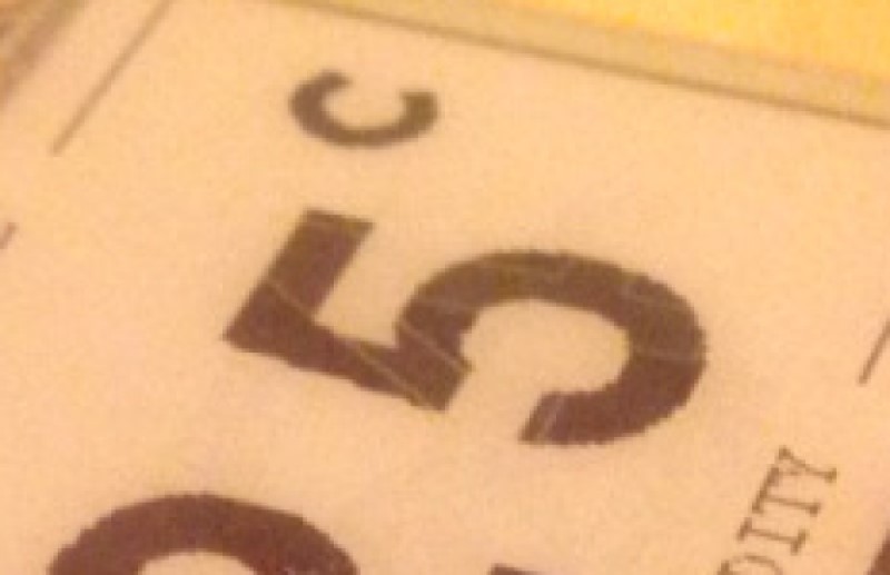
-
The work of the program was changed. Now the screen update is better. Looks more beautiful :)
-
@berkseo cool thanks for your update, really impressive which detail you are aiming to achieve!
I'm planning to get some as soon as possible :-) already gathering the parts. Any chance you upload the PCB?@jeti said in 💬 EFEKTA Temp&Hum sensor(ver. nRF52832 )+E-Ink display:
cool thanks for your update, really impressive which detail you are aiming to achieve!
I'm planning to get some as soon as possible already gathering the parts. Any chance you upload the PCB?PCB files have already been added, they are in the archives.
-
@berkseo I have ordered already the 10x PCB's and also most of the BOM. I'm also going to order one full mounted PCB (if still available).
Can you do me a favour: I need one decimal digit for the temp (not required for hum) but certainly for the temp!
Here is a hint/proposal: You can make the decimal digit smaller. I attach one sample from a Xiaomi device (unfortunatly has no wireless and not sure if/how it can be hacked and wireless added).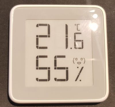
-
@berkseo I have ordered already the 10x PCB's and also most of the BOM. I'm also going to order one full mounted PCB (if still available).
Can you do me a favour: I need one decimal digit for the temp (not required for hum) but certainly for the temp!
Here is a hint/proposal: You can make the decimal digit smaller. I attach one sample from a Xiaomi device (unfortunatly has no wireless and not sure if/how it can be hacked and wireless added).@heinzv said in 💬 EFEKTA Temp&Hum sensor(ver. nRF52832 )+E-Ink display:
I have ordered already the 10x PCB's and also most of the BOM. I'm also going to order one full mounted PCB (if still available).
Can you do me a favour: I need one decimal digit for the temp (not required for hum) but certainly for the temp!
Here is a hint/proposal: You can make the decimal digit smaller. I attach one sample from a Xiaomi device (unfortunatly has no wireless and not sure if/how it can be hacked and wireless added).Do you want me to change the SOFTWARE a bit? Well, I do not think this is a problem. Question ... Maybe you like some kind of special font? I don’t know which one to use. I can also add technical sensors that can set device parameters through the controller of an intelligent home. An example of such sensors, see the video of my new prototype sensor. ... Now there is only one device left, but I plan to make a little more by the end of next week (I hope :)). Since I started posting my projects on openhardware, I realized that I don’t like to solder for sale, it’s not interesting :)
-
@berkseo I have ordered already the 10x PCB's and also most of the BOM. I'm also going to order one full mounted PCB (if still available).
Can you do me a favour: I need one decimal digit for the temp (not required for hum) but certainly for the temp!
Here is a hint/proposal: You can make the decimal digit smaller. I attach one sample from a Xiaomi device (unfortunatly has no wireless and not sure if/how it can be hacked and wireless added).@heinzv said in 💬 EFEKTA Temp&Hum sensor(ver. nRF52832 )+E-Ink display:
I have ordered already the 10x PCB's
Note, the device consists of two printed circuit boards, the order system on openhardware does not allow you to add two printed circuit boards for one device, just formed a second revision. For self-order download archives.
-
@berkseo Yes, I'd like to change the SW so that the temp shows also one decimal like 21,6 C
For the decimal a smaller font likes quite nice such as shown in the picture of the sensor from Xiaomi.
I don't have a specical font in mind but rather recommend to take proportional font rather than a mono-space font whcih is rather used for debugger output but not for a productive end user display. The space between the digits is typically smaller/less using a proportional font and looks more elegant than using mono-font.I know, that the 10 PCB's are 5 + 5 (5 sets).
I can imagine, that selling soldered PCB's is not a very interesting business and is boring and time consuming for just little amount of money. I was buying one just as reference and will solder the other 5 sets by myself. I know how much effort that is. -
@berkseo I have now the PCB's and my parts. Ihave now a few questions
1.) When can we expect the sketch code?
2.) Can we also have the schematics?
3.) How to you solder parts like the TPS62745DSSR? Are you using a reflow oven? or hot air or even a small solder iron? -
@berkseo I have now the PCB's and my parts. Ihave now a few questions
1.) When can we expect the sketch code?
2.) Can we also have the schematics?
3.) How to you solder parts like the TPS62745DSSR? Are you using a reflow oven? or hot air or even a small solder iron?- Added as a library with an example, see project page on openhardware
- Soon. ,..on PCB all marking is applied.
- First, I dissolve the flux paste and solder paste, apply a thin layer on the PCB. Installing a chip, clamping it with a reverse tweezer. Correct the position. It is then heated with a heat gun for soldering. Then remove the excess solder with a soldering iron (if any). It's simple, much harder to solder atmega 328.
I recently modified the boards, moved the elements on the power Board to the other side, made more convenient cutouts for mounting in the case. How to get ready fees, you will receive again this option further. Just all who made orders, please do not refuse payments, now a small delay in sending due to the fact that waiting for a new modification of the Board. All orders will be shipped.
-
- Added as a library with an example, see project page on openhardware
- Soon. ,..on PCB all marking is applied.
- First, I dissolve the flux paste and solder paste, apply a thin layer on the PCB. Installing a chip, clamping it with a reverse tweezer. Correct the position. It is then heated with a heat gun for soldering. Then remove the excess solder with a soldering iron (if any). It's simple, much harder to solder atmega 328.
I recently modified the boards, moved the elements on the power Board to the other side, made more convenient cutouts for mounting in the case. How to get ready fees, you will receive again this option further. Just all who made orders, please do not refuse payments, now a small delay in sending due to the fact that waiting for a new modification of the Board. All orders will be shipped.
@berkseo thanks a lot for the demo code. With some small correction I got it working (give some compile errors).
Could you please check if the font90.c is missing (which is used in the code but not found).
And there seem to be a typo (?) in the font36 (gives an error). I changed from Font24_Table to Font36_Table.
sFONT Font36 = {
Font24_Table,
41, /* Width /
46, / Height */
}; -
@berkseo thanks, that version works!
Maybe you can consider the one decimal digit for the temp (21,6 C). Otherwise I'll do some investigations.
The font90 will be too large (maybe font72) or we need a smaller font and the decimal digit can be a smaller font (mix of two fonts for temp e.g. font72 and font48).
Have you found a utility to convert fonts (e.g. TTF from Windwos) to generate matching font's for e-Paper (I have not yet found someting).
Since we have now enough RAM, have you thought about using the e-paper standard lib GxEPD? That has a least better font support (and also partial update)? -
@berkseo thanks, that version works!
Maybe you can consider the one decimal digit for the temp (21,6 C). Otherwise I'll do some investigations.
The font90 will be too large (maybe font72) or we need a smaller font and the decimal digit can be a smaller font (mix of two fonts for temp e.g. font72 and font48).
Have you found a utility to convert fonts (e.g. TTF from Windwos) to generate matching font's for e-Paper (I have not yet found someting).
Since we have now enough RAM, have you thought about using the e-paper standard lib GxEPD? That has a least better font support (and also partial update)?@heinzv Yes, I plan to add one-tenth resolution.
Convert numbers and letters to an array in C is simple. I use a program TheDotFactory. http://www.eran.io/the-dot-factory-an-lcd-font-and-image-generator/I would be glad if someone made his version of the software in the public domain.
Please show photos of your assembled working device.
-
@heinzv Yes, I plan to add one-tenth resolution.
Convert numbers and letters to an array in C is simple. I use a program TheDotFactory. http://www.eran.io/the-dot-factory-an-lcd-font-and-image-generator/I would be glad if someone made his version of the software in the public domain.
Please show photos of your assembled working device.
@berkseo I found out, that I still miss two parts (from AE), everything else is there. So I started a testing with my development boards.
I attach a picture of this setup. I use a CBYTE nRF52832 module, a SHT35 (SHT20 is not there and the 1uF capacitors for the bare e-paper displays) and a waveshare e-paper with PCB.
I'm now out for two weeks and will then have my parts hopefully.
The module on the right side is my BMP (black magic probe).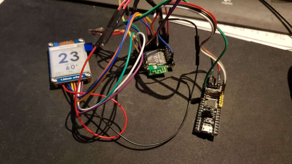
-
@berkseo I found out, that I still miss two parts (from AE), everything else is there. So I started a testing with my development boards.
I attach a picture of this setup. I use a CBYTE nRF52832 module, a SHT35 (SHT20 is not there and the 1uF capacitors for the bare e-paper displays) and a waveshare e-paper with PCB.
I'm now out for two weeks and will then have my parts hopefully.
The module on the right side is my BMP (black magic probe).@heinzv said in 💬 EFEKTA Temp&Hum sensor(ver. nRF52832 )+E-Ink display:
CBYTE nRF52832
I have a question for you, teach:). Do you use CBYTE nRF52832 and Arduino IDE? I was unable to run these modules. How did you manage that? Did you add inductance to the circuit? I assembled my own nRF52 modules according to the scheme DC-DC from Datasheet (I needed a module on components of size 0603 and 0805 for convenient soldering), the scheme worked and the device is perfectly stitched through the ARDUINO IDE
https://www.youtube.com/watch?v=hXmxzo0OiMs -
@berkseo (update): What kind of probems did you face? Why have you been unable to run this modules in the Arduino? Did you have problmes to upload the sketch?
Maybe you had the problem, that the modules are not detected during upload!
I had the same problem and the EBYTE E73 nRF52832 modules are locked by factory and thus not detected by the IDE's. You can unloack them with nRF Go studio, nrfutil (or nrfprog) and do a mass erase. In nRF Go studio you might require a J-Link programmer, you can olaso unlock it with openocd with a simple cheap ST-Link adapter.
openocd -s $OPENOCD/tcl -f interface/stlink-v2.cfg -f target/nrf52.cfg -c init -c "reset init" -c halt -c "nrf52 mass_erase" -c "program $FIRMWARE verify" -c reset -c exitI typically use the nRF52 modules with my selfmade Black Magic Probe (1.60), which is supported by Arduino IDE.
The EBYE modules have all the Nordic reference design parts soldered. So nothing else is required (no coils etc.)Here are my two modules which work:
I found this breakout boards for the E73 module here
https://oshpark.com/shared_projects/q4weF4UL
The other module were designed by ranseyer and myselflet me know if you have more questions
-
@berkseo (update): What kind of probems did you face? Why have you been unable to run this modules in the Arduino? Did you have problmes to upload the sketch?
Maybe you had the problem, that the modules are not detected during upload!
I had the same problem and the EBYTE E73 nRF52832 modules are locked by factory and thus not detected by the IDE's. You can unloack them with nRF Go studio, nrfutil (or nrfprog) and do a mass erase. In nRF Go studio you might require a J-Link programmer, you can olaso unlock it with openocd with a simple cheap ST-Link adapter.
openocd -s $OPENOCD/tcl -f interface/stlink-v2.cfg -f target/nrf52.cfg -c init -c "reset init" -c halt -c "nrf52 mass_erase" -c "program $FIRMWARE verify" -c reset -c exitI typically use the nRF52 modules with my selfmade Black Magic Probe (1.60), which is supported by Arduino IDE.
The EBYE modules have all the Nordic reference design parts soldered. So nothing else is required (no coils etc.)Here are my two modules which work:
I found this breakout boards for the E73 module here
https://oshpark.com/shared_projects/q4weF4UL
The other module were designed by ranseyer and myselflet me know if you have more questions
@heinzv said in 💬 EFEKTA Temp&Hum sensor(ver. nRF52832 )+E-Ink display:
nRF Go studio
How do I unlock (if locked) E73 with nRF Go studio ? What should be done, what actions?
- Connect E73 to J-Link
- Connect J-Link to the USB port of the computer
3.??
4.??
..
-
@heinzv said in 💬 EFEKTA Temp&Hum sensor(ver. nRF52832 )+E-Ink display:
nRF Go studio
How do I unlock (if locked) E73 with nRF Go studio ? What should be done, what actions?
- Connect E73 to J-Link
- Connect J-Link to the USB port of the computer
3.??
4.??
..
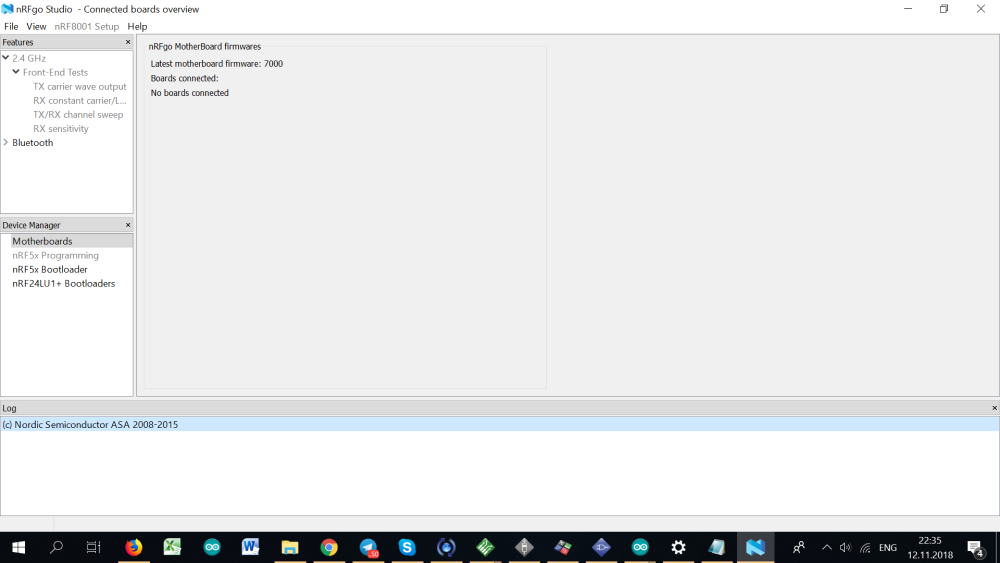
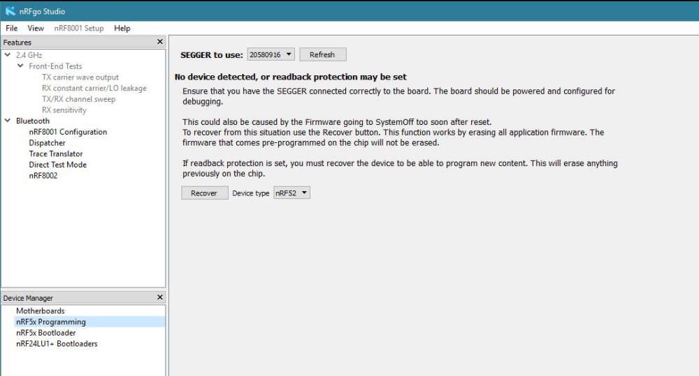
@berkseo you have to connect your E73 module with a J-Link adapter, if the adapter is recognized by nRFgo Studio, the nRFx Programming will be enabled (turn from grey to black) and then you can select "Recover" (only shown if you have a locked device). You should do then also a "Erase all").
Again, it only works with a Segger compatible J-Link adapter. Do you have one? It is anyhow recommended if you want to use Segger Embedded Studio (required for using the nRF52840 and the newest 15.2 SDK).
The other/second method could work with a ST-Link or black magic probe (a 2€ clone can do it, I created a couple of them) and with openocd.The unlock screen look like this, if you have a locked or no device connected but a valied J-Link adapter
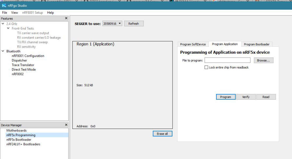
And after recover, you get a screen like this to erase or flash a program
-
@berkseo you have to connect your E73 module with a J-Link adapter, if the adapter is recognized by nRFgo Studio, the nRFx Programming will be enabled (turn from grey to black) and then you can select "Recover" (only shown if you have a locked device). You should do then also a "Erase all").
Again, it only works with a Segger compatible J-Link adapter. Do you have one? It is anyhow recommended if you want to use Segger Embedded Studio (required for using the nRF52840 and the newest 15.2 SDK).
The other/second method could work with a ST-Link or black magic probe (a 2€ clone can do it, I created a couple of them) and with openocd.The unlock screen look like this, if you have a locked or no device connected but a valied J-Link adapter
And after recover, you get a screen like this to erase or flash a program
@heinzv
Thanks for the tips, very hard to find information. I have a pair of j-link adapters. There are also several different clones of st-link v2. (but I don't have a linux machine now.) I'll try nRFgo Studio tomorrow. Earlier I wrote that I assembled my Assembly nRF52832 (dc-dc), no problems in the Arduino IDE(chips in the ribbon, see the link below). So I thought that the E73 modules do not work because of a slightly different circuit (see photo without cover) in the circuit no inductance on the DCC pin and no connection outputs through inductance to the DEC4 pin.
https://ru.aliexpress.com/item/Free-shipping-NRF52832-QFAA-NRF52832-QFAA-R-N52832-NRF52832-5pcs-lot-100-NEW-and-ORIGINAL/32828951084.html?spm=a2g0v.10010108.1000016/B.1.10a9e326lCcYJ6&isOrigTitle=true -
@heinzv
Thanks for the tips, very hard to find information. I have a pair of j-link adapters. There are also several different clones of st-link v2. (but I don't have a linux machine now.) I'll try nRFgo Studio tomorrow. Earlier I wrote that I assembled my Assembly nRF52832 (dc-dc), no problems in the Arduino IDE(chips in the ribbon, see the link below). So I thought that the E73 modules do not work because of a slightly different circuit (see photo without cover) in the circuit no inductance on the DCC pin and no connection outputs through inductance to the DEC4 pin.
https://ru.aliexpress.com/item/Free-shipping-NRF52832-QFAA-NRF52832-QFAA-R-N52832-NRF52832-5pcs-lot-100-NEW-and-ORIGINAL/32828951084.html?spm=a2g0v.10010108.1000016/B.1.10a9e326lCcYJ6&isOrigTitle=true@berkseo I have updated my post above with an additiona picture.
You can do all on Windows (I mostly use Windows 10 x64). I sometimes use Linux like for creating the BMP clones. I'm using the latest Mint version in a VMware VM.
Let me know if you need more infos ...BTW: I was further working on the own created nRF52832 PCB's with ePaper (I have many E73 modules left) and will start soldering the PCB's I have ordered from you if all parts are there (most of thema are).
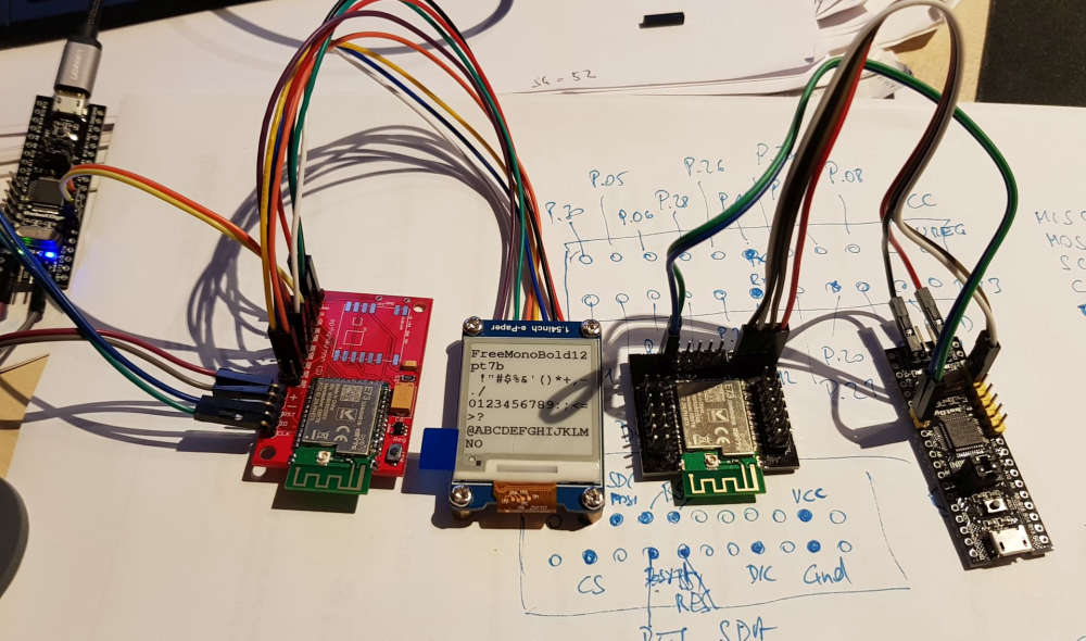
The one ordered soldered module is still in transit (or I did not get it so far).Below another picture of the ePaper output. I have tested the idea with two fonts: The larger one for the non decimals and a smaller one for the decimal. I'm using the GxEPD standard e-Paper library in my latested sketch, as it's easier to use, has more fonts und is ready for more ePaper modules/sizes.
It is just an intermediate state (batter symbol, larger font missing etc.).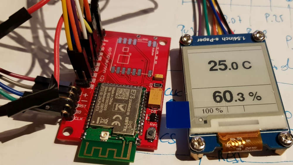
Hello! It looks like you're interested in this conversation, but you don't have an account yet.
Getting fed up of having to scroll through the same posts each visit? When you register for an account, you'll always come back to exactly where you were before, and choose to be notified of new replies (either via email, or push notification). You'll also be able to save bookmarks and upvote posts to show your appreciation to other community members.
With your input, this post could be even better 💗
Register Login