Door + flood sensor
-
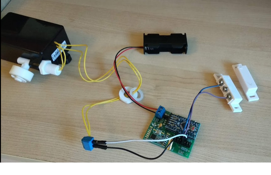
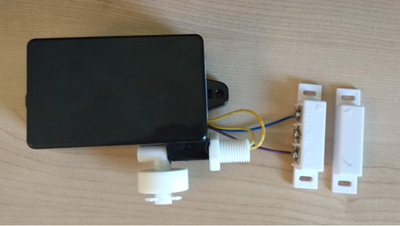
Pretty simple door + flood project based on @sundberg84 EasyPCB RFM69 board with attached a:
- Flood sensor: https://www.aliexpress.com/item/DC-220V-Liquid-Water-Level-Sensor-Right-Angle-Float-Switch-for-Fish-Tank/32643554836.html
- Door sensor: https://www.aliexpress.com/item/10pairs-lot-NC-and-NO-two-kinds-type-Wired-Metal-Roller-Shutter-Door-Magnetic-Contact-Switch/32843185792.html
Both the sensors have one wire connected to Ground and on the other wire to an Arduino pin. Principle is simple: we write HIGH to the pin (or let NodeManager doing the job), when the sensor switches (e.g. the circuit is closed), we catch the FALLING interrupt (or the LOW value).
Since battery powered, the door sensor has to be normally open (e.g. when the door is closed, the circuit is open and no current is wasted). Many Chinese vendors, at least from my experience, makes confusion on this topic and send the wrong one or call it in a wrong way. This is why I bought those sensors with both NO and NC, so I'm sure to have enough flexibility.
Code with NodeManager's is pretty simple, down below. Only caveat is both the sensors theoretically would be interrupt based but on a Pro Mini there is only one usable pin for it. I've gone crazy trying to use PinChangeInterrupt with NodeManager so eventually I decided to go for the easy way: if there is a water leakage inside my house, I can wait up to 5 minutes, so I'm just polling the flood sensor's pin periodically and send the value to the controller at a regular interval (using SensorDigitalInput).
Pictures of the project down below.
/**********************************
 * MySensors node configuration
 */

// General settings
#define SKETCH_NAME "Door"
#define SKETCH_VERSION "1.0"
//#define MY_DEBUG
#define MY_NODE_ID 5

// RFM69 radio settings
#define MY_RADIO_RFM69
//#define MY_RFM69_FREQUENCY RFM69_433MHZ
#define MY_IS_RFM69HW
#define MY_RFM69_NEW_DRIVER
//#define MY_RFM69_ENABLE_ENCRYPTION
#define MY_RFM69_NETWORKID 110
//#define MY_DEBUG_VERBOSE_RFM69
//#define MY_RF69_IRQ_PIN D1
//#define MY_RF69_IRQ_NUM MY_RF69_IRQ_PIN
//#define MY_RF69_SPI_CS D2
//#define MY_RFM69_ATC_MODE_DISABLED

// Advanced settings
#define MY_BAUD_RATE 9600
//#define MY_SMART_SLEEP_WAIT_DURATION_MS 500
#define MY_SPLASH_SCREEN_DISABLED
//#define MY_DISABLE_RAM_ROUTING_TABLE_FEATURE
//#define MY_SIGNAL_REPORT_ENABLED

/***********************************
 * NodeManager modules for supported sensors
 */

#define USE_BATTERY
#define USE_SIGNAL
#define USE_CONFIGURATION
#define USE_DIGITAL_INPUT
#define USE_INTERRUPT

/***********************************
 * NodeManager built-in features
 */

// Enable/disable NodeManager's features
#define FEATURE_DEBUG ON
#define FEATURE_POWER_MANAGER OFF
#define FEATURE_INTERRUPTS ON
#define FEATURE_CONDITIONAL_REPORT OFF
#define FEATURE_EEPROM OFF
#define FEATURE_SLEEP ON
#define FEATURE_RECEIVE ON
#define FEATURE_TIME OFF
#define FEATURE_RTC OFF
#define FEATURE_SD OFF
#define FEATURE_HOOKING OFF

/***********************************
 * Load NodeManager Library
 */

#include "NodeManagerLibrary.h"
NodeManager node;

/***********************************
 * Add your sensors below
 */

// built-in sensors
SensorBattery battery(node);
SensorConfiguration configuration(node);
SensorSignal signal(node);

// Attached sensors
SensorDigitalInput flood(node,6);
SensorMotion door(node,3);

/***********************************
 * Main Sketch
 */

// before
void before() {
  // setup the serial port baud rate
  Serial.begin(MY_BAUD_RATE);
  /*
  * Configure your sensors below
  */

  // battery sensor
  battery.setMinVoltage(1.8);
  battery.setMaxVoltage(3.2);

  // door sensor
  door.setInitialValue(HIGH);
  door.setInterruptMode(FALLING);
  door.setInvertValueToReport(true);

  // flood sensor
  flood.setReportIntervalMinutes(5);
  flood.children.get(1)->setPresentation(S_BINARY);
  flood.children.get(1)->setType(V_STATUS);

  // node configuration
  node.setSleepMinutes(5);

  /*
  * Configure your sensors above
  */
  node.before();
}

// presentation
void presentation() {
  // call NodeManager presentation routine
  node.presentation();
}

// setup
void setup() {
  // call NodeManager setup routine
  node.setup();
}

// loop
void loop() {
  // call NodeManager loop routine
  node.loop();
}

#if FEATURE_RECEIVE == ON
// receive
void receive(const MyMessage &message) {
  // call NodeManager receive routine
  node.receive(message);
}
#endif

#if FEATURE_TIME == ON
// receiveTime
void receiveTime(unsigned long ts) {
  // call NodeManager receiveTime routine
  node.receiveTime(ts);
}
#endif

-
Good project. Can you please share more details with schematics and the board layout? I would like to build this one.
Thanks.@jhussain the board used is available here: https://www.openhardware.io/view/4/EasyNewbie-PCB-for-MySensors (for nrf24) and https://www.openhardware.io/view/389/EasyNewbie-PCB-RFM69-HWW-edition-for-MySensors for rfm69
-
@jhussain the board used is available here: https://www.openhardware.io/view/4/EasyNewbie-PCB-for-MySensors (for nrf24) and https://www.openhardware.io/view/389/EasyNewbie-PCB-RFM69-HWW-edition-for-MySensors for rfm69
@jhussain the board is the one pointed out by @mfalkvidd and as for the wiring it is very simple: the door sensor has one wire connected to pin 3 (since interrupt based) and the other to ground, the flood sensor has one connected to pin 6 (can be any) and the other to ground.
