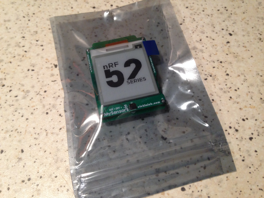
💬 EFEKTA Temp&Hum sensor(ver. nRF52 )+E-Ink display


  • ... and it seems that this project is less interesting than its predecessor on atmega328 ... (if it estimate by the number of likes)

    Apparently a new chip causes misunderstanding.


  • @berkseo I gave it at least one more like. Fo me it is one of the most interesting projects! With the Atmega328, we are on a dead end and this is the next step we have to go.
    I'm not just interested in the PCB and the code but also how you integrate/mount the "plain" epaper with the "foil-connector" which is much cheaper such as 5.99us$ (see below)
    So I'm looking forward when the stuff is available. That is exactly what I'm trying to achive since a long time!

    https://www.aliexpress.com/item/WFC0000CZ07-1-54-200x200-e-ink/32814074862.html?spm=2114.search0104.3.151.42736564L6Hvwq&ws_ab_test=searchweb0_0,searchweb201602_5_10065_10068_10547_10059_10884_10548_10887_10696_100031_10084_10083_10103_10618_10304_10307_10820_10821_10302,searchweb201603_60,ppcSwitch_4&algo_expid=be678964-275d-4b20-a162-2a7ef1e8ba04-23&algo_pvid=be678964-275d-4b20-a162-2a7ef1e8ba04&transAbTest=ae803_2&priceBeautifyAB=0.


  • you might consider even the nRF52840 instead of the 832 as it supports BLE 5 with long range (the 832 does not) and ZigBee.


  • are you satisfied with the nRF52xx and does it work properly? I hope sometime we get the project infos to make some sensors too 🙂


  • @heinzv

    I'm satisfied, it work perfectly. I found ready-made modules that can be used by every user without learning, in the Arduino IDE, this was my main task. Now the self-made prototype is on testing, PCB ordered in production. After some time, the development will be available.
    0_1537950362580_567.png


  • @berkseo That looks awsome, great work. One of the best projects (HW and SW) I have seen. Exactly what I need!!! I can't wait to get your PCB layout and the project code.


  • @berkseo once I got it/use it I will make a donation (I think you deserve it)


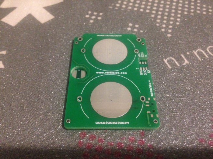
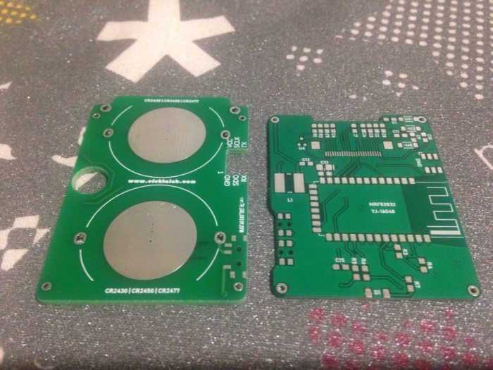
  • Received printed circuit boards. Soldering tomorrow :))
    0_1538766112005_5FCAFE9D-9869-4768-A744-57407A8BB3389.jpg


  • Looking good! Please keep up the awesome work.


  • @berkseo any chance you can provide a brief feedback?
    What is your status on the software side?


  • @jeti said in 💬 Temperature and humidity sensor(ver.NRF52832)+E-Ink display:

    any chance you can provide a brief feedback?
    What is your status on the software side?

    For nrf52832 was tested software developed for the atmega328. Need to alter the fonts and graphics, to improve, because this chip have more opportunities. This is not difficult. There will be an update soon.


  • @berkseo thanks!


  • update,
    nRF52832 MySensors – 01:15
    — Andrew EfektaSB

    It remains a bit to fix the program(improve graphics), as the demo uses software from the version on atmega328


  • @berkseo awesome! Great work!
    One question: the high temperature is a result of testing? So with a long enough sleep time the temp will be accurate?


  • @jeti said in 💬 EFEKTA Temp&Hum sensor(ver. nRF52832 )+E-Ink display:

    One question: the high temperature is a result of testing? So with a long enough sleep time the temp will be accurate?

    Don't quite understand the question. The chip is not heated. No matter how much the device sleeps, the temperature sensor also sleeps. A digital temperature and humidity sensor is used.


  • @berkseo on the second restart the temperature shows 46°C that's why in wondered of this is caused by testing. As during "normal" using this should not be an issue


  • @jeti
    On video, now I understand)). Used software for the Atmega328 , so was error. This chip is very fast. I fix it.


  • @berkseo ah thanks. If you need somebody to test. I would be happy to do so.


  • Once the code is available I would order 10x PCB's.
    Also, do you have a link to the nRF52832 module? (a 840 version would be also very nice :-))

    ok, I just odered the 5 PCB Sets.
    Beside the link to the nRF52832 Module, please provide also the link to the e-Paper Module.


  • This post is deleted!

  • Admin

    Really nice design..

    Could you please post the schematics / board files as well, as this is a openhardware site.

    Also if you upload the gerber files directly (not in a zip / rar file), then the openhardware.io site is able to render 3D views of the boards etc.


  • @heinzv said in 💬 EFEKTA Temp&Hum sensor(ver. nRF52832 )+E-Ink display:

    Once the code is available I would order 10x PCB's.
    Also, do you have a link to the nRF52832 module? (a 840 version would be also very nice :-))
    ok, I just odered the 5 PCB Sets.
    Beside the link to the nRF52832 Module, please provide also the link to the e-Paper Module.

    Code in the work. BOM added.


  • @tbowmo
    Thank you for rating. I will lay out the scheme in the near future, it needs to be drawn :). 3D-model does not work, it turns out a piece of cheese. I work at Diptrace( https://diptrace.com ), but this problem is not only mine - https://forum.mysensors.org/topic/9528/temperature-and-humidity-sensor-ver-atmega328-e-ink-display/30


  • @heinzv
    Still no support nRF52840 in the Arduino IDE. What Sandeepmistry implemented uses is the old SDK ...still. I am guided by this editor as it is easy to use for regular users as well as MySensors 🙂


  • 0_1539358761851_IMG_2608.JPG

    0_1539358778599_IMG_2609.JPG


  • @berkseo it looks very good! Is testing running good?
    Any hickups ?


  • @jeti
    So far I'm satisfied, there is one point with updating the screen. I do not really want to do a full update in the program, but probably have to. Partial update gives the effect of visible lines from the previous symbol. Look at the photo, but it is a problem of code and beauty 🙂

    0_1539523404628_IMG_25941111.jpg


  • @berkseo cool thanks for your update, really impressive which detail you are aiming to achieve!
    I'm planning to get some as soon as possible 🙂 already gathering the parts. Any chance you upload the PCB?


  • The work of the program was changed. Now the screen update is better. Looks more beautiful 🙂

    MySensors nRF52832 | Temperature & Humidity sensor with e-Paper display 1.54 | EFEKTA (prototype) II – 01:36
    — Andrew EfektaSB


  • @jeti said in 💬 EFEKTA Temp&Hum sensor(ver. nRF52832 )+E-Ink display:

    cool thanks for your update, really impressive which detail you are aiming to achieve!
    I'm planning to get some as soon as possible already gathering the parts. Any chance you upload the PCB?

    PCB files have already been added, they are in the archives.


  • @berkseo I have ordered already the 10x PCB's and also most of the BOM. I'm also going to order one full mounted PCB (if still available).
    Can you do me a favour: I need one decimal digit for the temp (not required for hum) but certainly for the temp!
    Here is a hint/proposal: You can make the decimal digit smaller. I attach one sample from a Xiaomi device (unfortunatly has no wireless and not sure if/how it can be hacked and wireless added).

    0_1540133434810_temp-hum-sample.jpg


  • @heinzv said in 💬 EFEKTA Temp&Hum sensor(ver. nRF52832 )+E-Ink display:

    I have ordered already the 10x PCB's and also most of the BOM. I'm also going to order one full mounted PCB (if still available).
    Can you do me a favour: I need one decimal digit for the temp (not required for hum) but certainly for the temp!
    Here is a hint/proposal: You can make the decimal digit smaller. I attach one sample from a Xiaomi device (unfortunatly has no wireless and not sure if/how it can be hacked and wireless added).

    Do you want me to change the SOFTWARE a bit? Well, I do not think this is a problem. Question ... Maybe you like some kind of special font? I don’t know which one to use. I can also add technical sensors that can set device parameters through the controller of an intelligent home. An example of such sensors, see the video of my new prototype sensor. ... Now there is only one device left, but I plan to make a little more by the end of next week (I hope :)). Since I started posting my projects on openhardware, I realized that I don’t like to solder for sale, it’s not interesting 🙂

    MySensors | First software test nRF52832 Temp&Hum&Baro&Forecast sensor BME280 | MySensors – 01:30
    — Andrew EfektaSB

    MySensors | BME280 sensor nRF52832 Power Consumption Test – 01:38
    — Andrew EfektaSB


  • @heinzv said in 💬 EFEKTA Temp&Hum sensor(ver. nRF52832 )+E-Ink display:

    I have ordered already the 10x PCB's

    Note, the device consists of two printed circuit boards, the order system on openhardware does not allow you to add two printed circuit boards for one device, just formed a second revision. For self-order download archives.


  • @berkseo Yes, I'd like to change the SW so that the temp shows also one decimal like 21,6 C
    For the decimal a smaller font likes quite nice such as shown in the picture of the sensor from Xiaomi.
    I don't have a specical font in mind but rather recommend to take proportional font rather than a mono-space font whcih is rather used for debugger output but not for a productive end user display. The space between the digits is typically smaller/less using a proportional font and looks more elegant than using mono-font.

    I know, that the 10 PCB's are 5 + 5 (5 sets).
    I can imagine, that selling soldered PCB's is not a very interesting business and is boring and time consuming for just little amount of money. I was buying one just as reference and will solder the other 5 sets by myself. I know how much effort that is.


  • @berkseo I have now the PCB's and my parts. Ihave now a few questions
    1.) When can we expect the sketch code?
    2.) Can we also have the schematics?
    3.) How to you solder parts like the TPS62745DSSR? Are you using a reflow oven? or hot air or even a small solder iron?


  • @heinzv

    1. Added as a library with an example, see project page on openhardware
    2. Soon. ,..on PCB all marking is applied.
    3. First, I dissolve the flux paste and solder paste, apply a thin layer on the PCB. Installing a chip, clamping it with a reverse tweezer. Correct the position. It is then heated with a heat gun for soldering. Then remove the excess solder with a soldering iron (if any). It's simple, much harder to solder atmega 328.

    I recently modified the boards, moved the elements on the power Board to the other side, made more convenient cutouts for mounting in the case. How to get ready fees, you will receive again this option further. Just all who made orders, please do not refuse payments, now a small delay in sending due to the fact that waiting for a new modification of the Board. All orders will be shipped.


  • @berkseo thanks a lot for the demo code. With some small correction I got it working (give some compile errors).
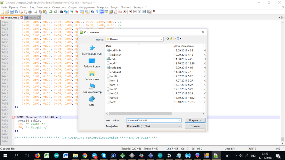
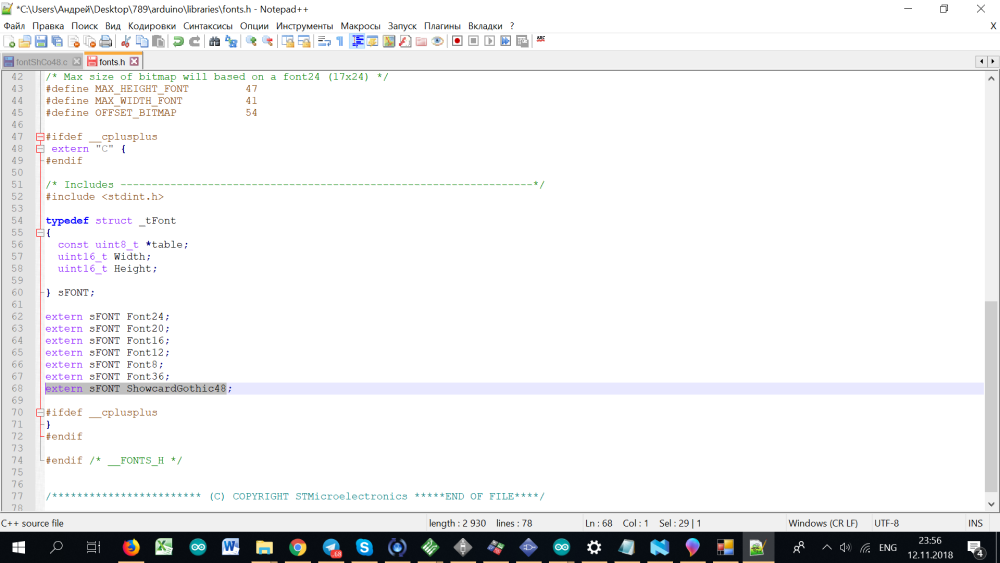
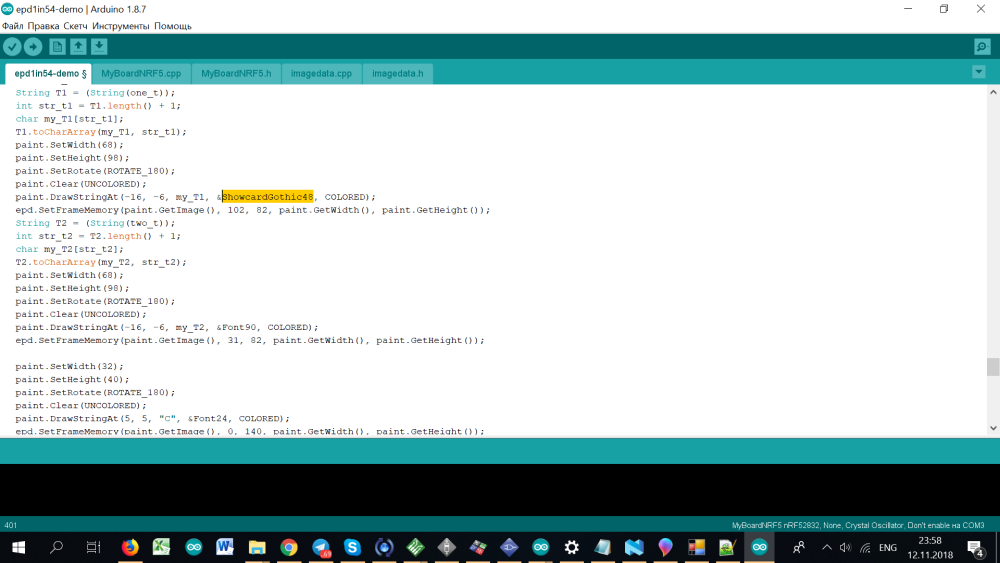
    Could you please check if the font90.c is missing (which is used in the code but not found).
    And there seem to be a typo (?) in the font36 (gives an error). I changed from Font24_Table to Font36_Table.
    sFONT Font36 = {
    Font24_Table,
    41, /* Width /
    46, /
    Height */
    };


  • @heinzv
    Uploaded the updated archive to Google drive. Download again


  • @berkseo thanks, that version works!
    Maybe you can consider the one decimal digit for the temp (21,6 C). Otherwise I'll do some investigations.
    The font90 will be too large (maybe font72) or we need a smaller font and the decimal digit can be a smaller font (mix of two fonts for temp e.g. font72 and font48).
    Have you found a utility to convert fonts (e.g. TTF from Windwos) to generate matching font's for e-Paper (I have not yet found someting).
    Since we have now enough RAM, have you thought about using the e-paper standard lib GxEPD? That has a least better font support (and also partial update)?


  • @heinzv Yes, I plan to add one-tenth resolution.
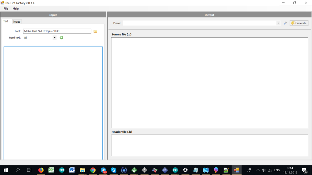
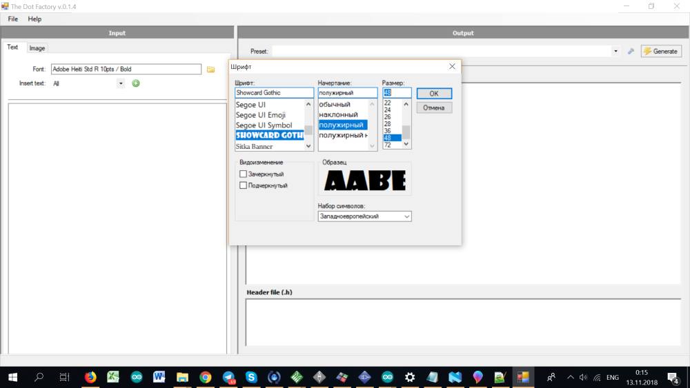
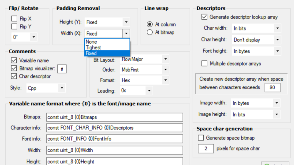
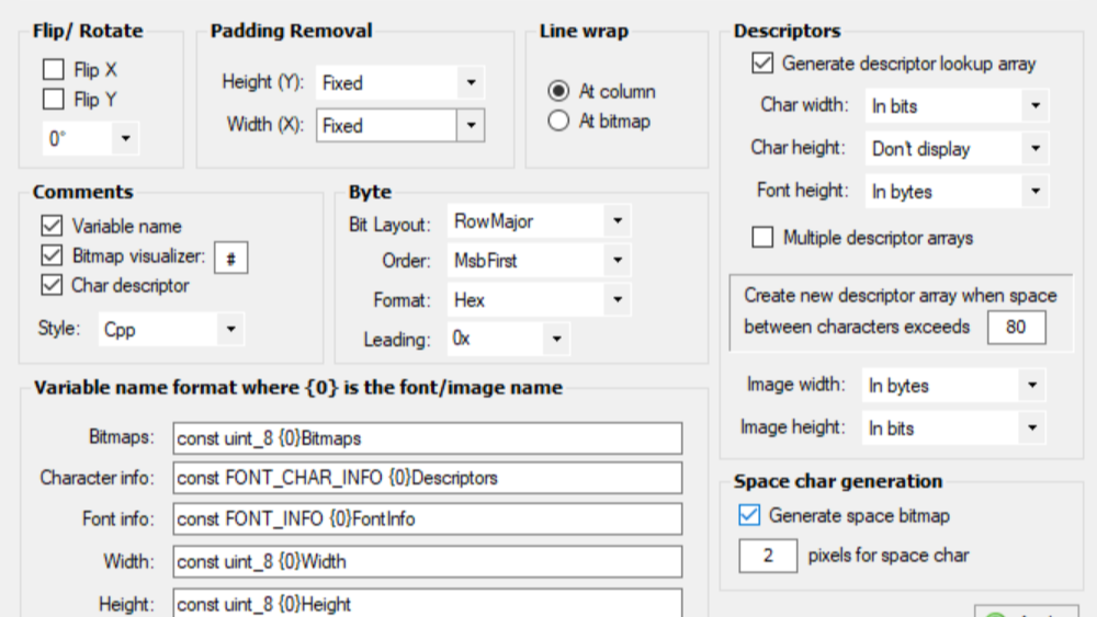
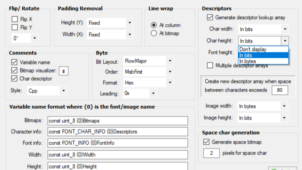
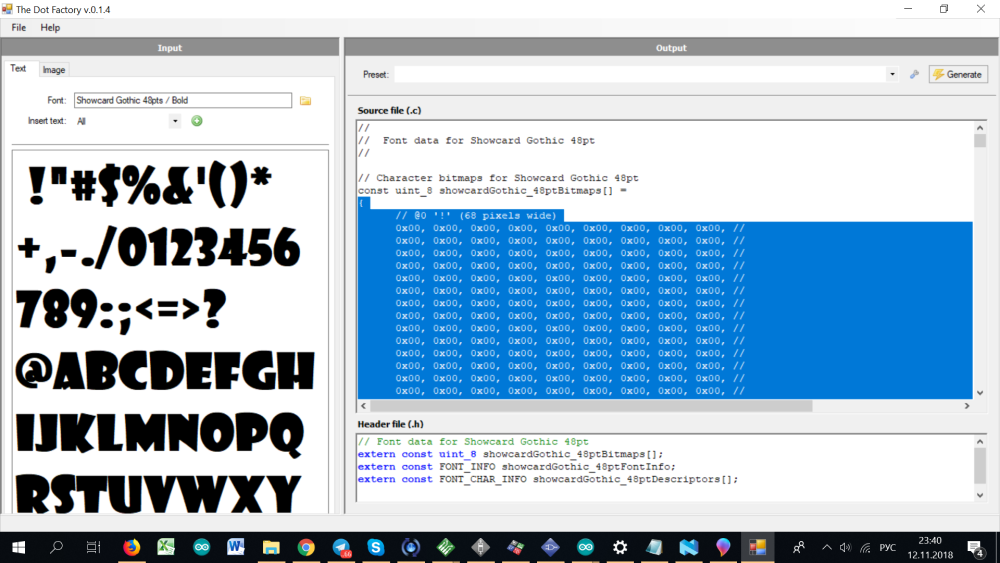
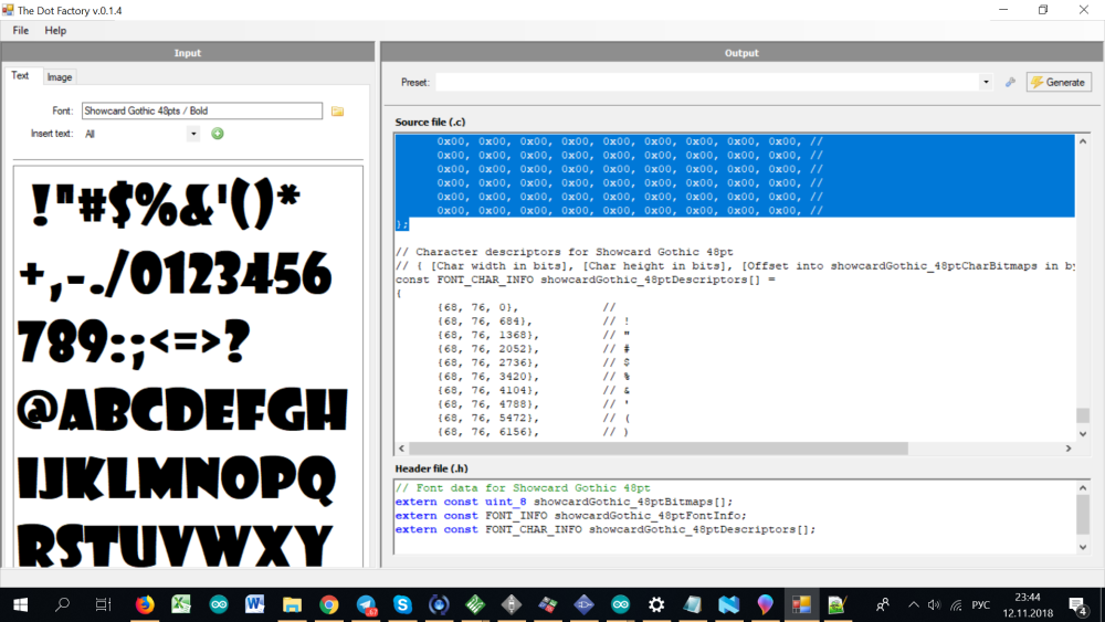
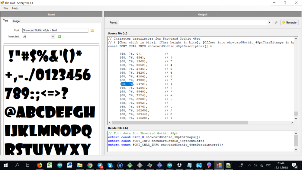
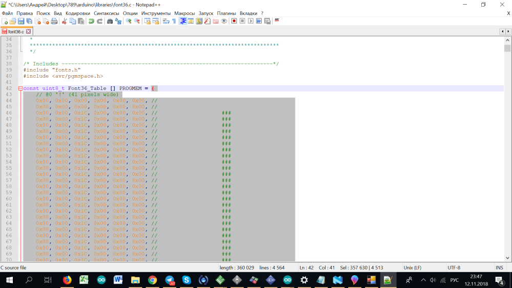
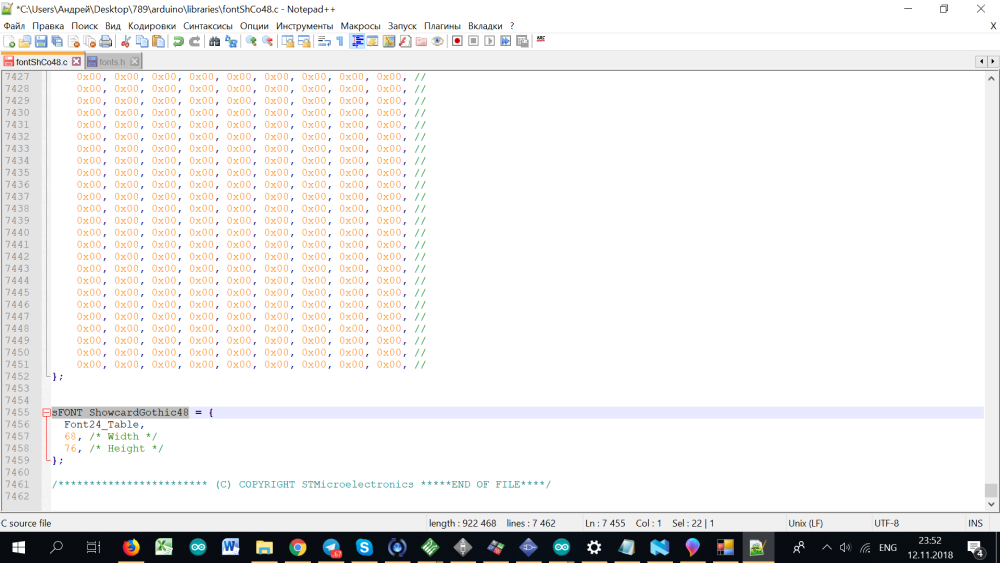
    Convert numbers and letters to an array in C is simple. I use a program TheDotFactory. http://www.eran.io/the-dot-factory-an-lcd-font-and-image-generator/

    I would be glad if someone made his version of the software in the public domain.

    Please show photos of your assembled working device.


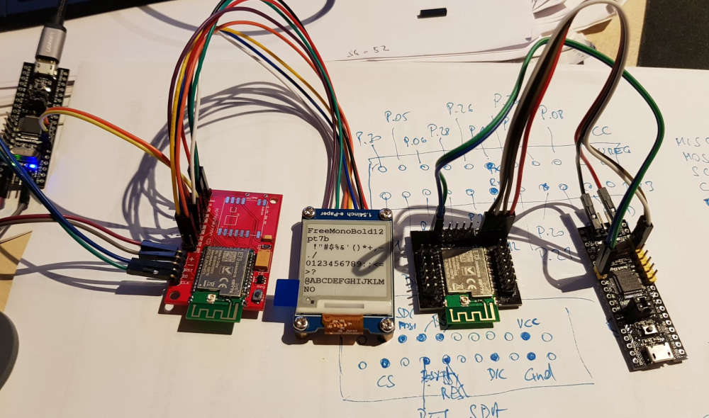
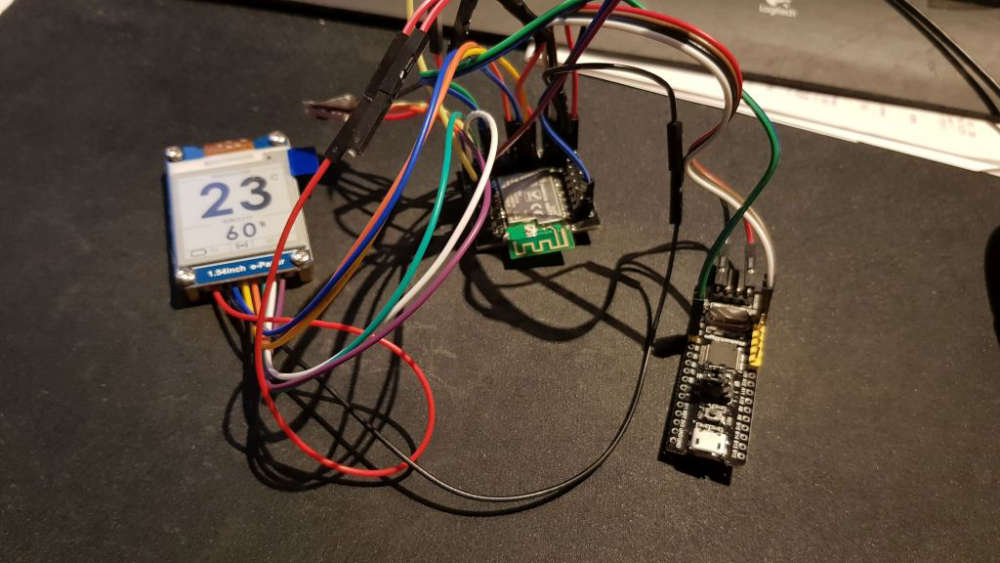
  • @berkseo I found out, that I still miss two parts (from AE), everything else is there. So I started a testing with my development boards.
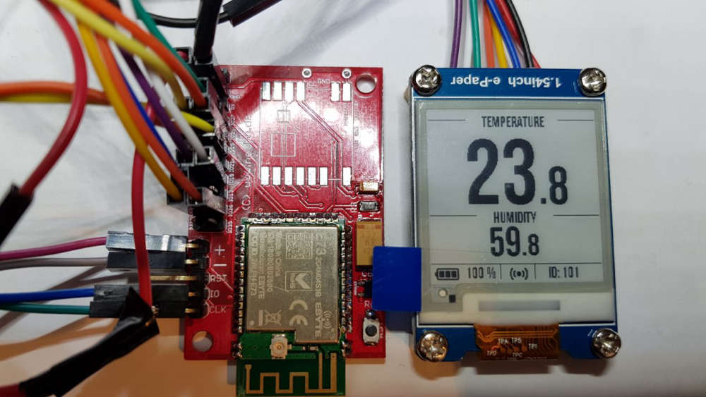
    I attach a picture of this setup. I use a CBYTE nRF52832 module, a SHT35 (SHT20 is not there and the 1uF capacitors for the bare e-paper displays) and a waveshare e-paper with PCB.
    I'm now out for two weeks and will then have my parts hopefully.
    The module on the right side is my BMP (black magic probe).
    0_1541368815435_nRF52_Temp_Hum_Test.jpg


  • @heinzv said in 💬 EFEKTA Temp&Hum sensor(ver. nRF52832 )+E-Ink display:

    CBYTE nRF52832

    I have a question for you, teach:). Do you use CBYTE nRF52832 and Arduino IDE? I was unable to run these modules. How did you manage that? Did you add inductance to the circuit? I assembled my own nRF52 modules according to the scheme DC-DC from Datasheet (I needed a module on components of size 0603 and 0805 for convenient soldering), the scheme worked and the device is perfectly stitched through the ARDUINO IDE
    MySensors | nRF52832 Motion sensor | first software test – 01:00
    — Andrew EfektaSB


  • @berkseo (update): What kind of probems did you face? Why have you been unable to run this modules in the Arduino? Did you have problmes to upload the sketch?
    Maybe you had the problem, that the modules are not detected during upload!
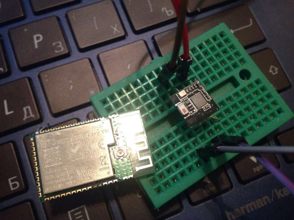
    I had the same problem and the EBYTE E73 nRF52832 modules are locked by factory and thus not detected by the IDE's. You can unloack them with nRF Go studio, nrfutil (or nrfprog) and do a mass erase. In nRF Go studio you might require a J-Link programmer, you can olaso unlock it with openocd with a simple cheap ST-Link adapter.
    openocd -s $OPENOCD/tcl -f interface/stlink-v2.cfg -f target/nrf52.cfg -c init -c "reset init" -c halt -c "nrf52 mass_erase" -c "program $FIRMWARE verify" -c reset -c exit

    I typically use the nRF52 modules with my selfmade Black Magic Probe (1.60), which is supported by Arduino IDE.
    The EBYE modules have all the Nordic reference design parts soldered. So nothing else is required (no coils etc.)

    Here are my two modules which work:

    0_1541958594127_nRF52832_Breakout-Boards.jpg

    I found this breakout boards for the E73 module here
    https://oshpark.com/shared_projects/q4weF4UL
    The other module were designed by ranseyer and myself

    let me know if you have more questions


  • @heinzv said in 💬 EFEKTA Temp&Hum sensor(ver. nRF52832 )+E-Ink display:

    nRF Go studio

    How do I unlock (if locked) E73 with nRF Go studio ? What should be done, what actions?

    1. Connect E73 to J-Link
    2. Connect J-Link to the USB port of the computer
      3.??
      4.??
      ..
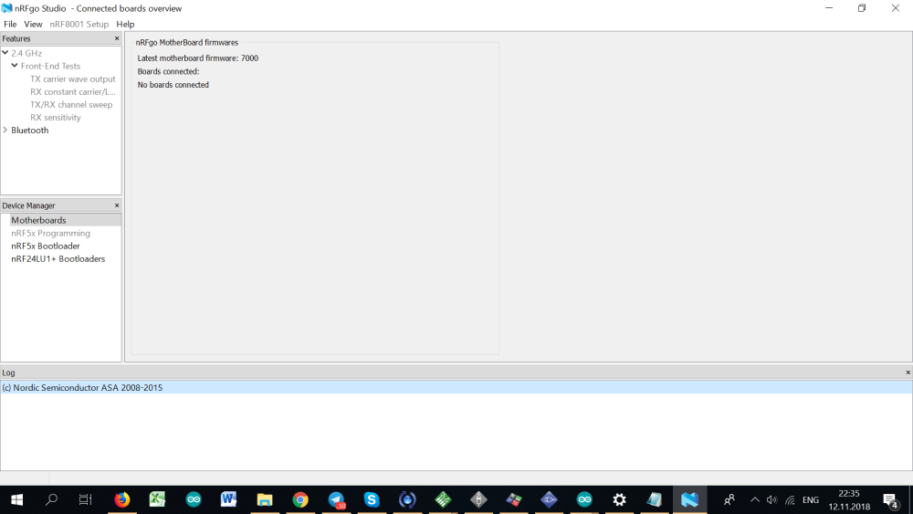
      0_1542051561395_nRFGO.png


  • @berkseo you have to connect your E73 module with a J-Link adapter, if the adapter is recognized by nRFgo Studio, the nRFx Programming will be enabled (turn from grey to black) and then you can select "Recover" (only shown if you have a locked device). You should do then also a "Erase all").
    Again, it only works with a Segger compatible J-Link adapter. Do you have one? It is anyhow recommended if you want to use Segger Embedded Studio (required for using the nRF52840 and the newest 15.2 SDK).
    The other/second method could work with a ST-Link or black magic probe (a 2€ clone can do it, I created a couple of them) and with openocd.

    The unlock screen look like this, if you have a locked or no device connected but a valied J-Link adapter
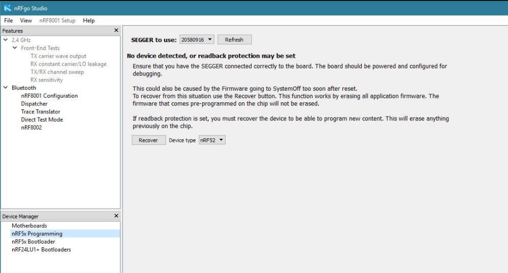
    0_1542053389286_nRF52_unlock_screen.jpg
    And after recover, you get a screen like this to erase or flash a program
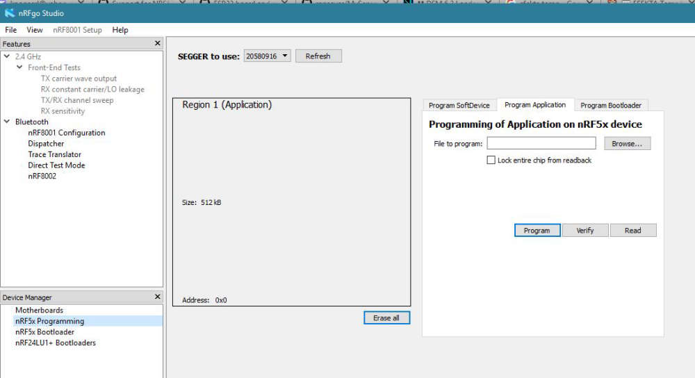
    0_1542052489515_nRF52_unlock.jpg


  • @heinzv
    Thanks for the tips, very hard to find information. I have a pair of j-link adapters. There are also several different clones of st-link v2. (but I don't have a linux machine now.) I'll try nRFgo Studio tomorrow. Earlier I wrote that I assembled my Assembly nRF52832 (dc-dc), no problems in the Arduino IDE(chips in the ribbon, see the link below). So I thought that the E73 modules do not work because of a slightly different circuit (see photo without cover) in the circuit no inductance on the DCC pin and no connection outputs through inductance to the DEC4 pin.
    https://ru.aliexpress.com/item/Free-shipping-NRF52832-QFAA-NRF52832-QFAA-R-N52832-NRF52832-5pcs-lot-100-NEW-and-ORIGINAL/32828951084.html?spm=a2g0v.10010108.1000016/B.1.10a9e326lCcYJ6&isOrigTitle=true


  • @berkseo I have updated my post above with an additiona picture.
    You can do all on Windows (I mostly use Windows 10 x64). I sometimes use Linux like for creating the BMP clones. I'm using the latest Mint version in a VMware VM.
    Let me know if you need more infos ...

    BTW: I was further working on the own created nRF52832 PCB's with ePaper (I have many E73 modules left) and will start soldering the PCB's I have ordered from you if all parts are there (most of thema are).
    The one ordered soldered module is still in transit (or I did not get it so far).

    Below another picture of the ePaper output. I have tested the idea with two fonts: The larger one for the non decimals and a smaller one for the decimal. I'm using the GxEPD standard e-Paper library in my latested sketch, as it's easier to use, has more fonts und is ready for more ePaper modules/sizes.
    It is just an intermediate state (batter symbol, larger font missing etc.).
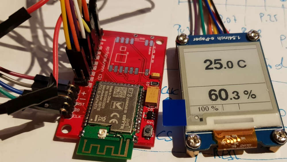
    0_1542054370888_nRF52_mySesnors_TempHum_ePaper.jpg


  • @heinzv said in 💬 EFEKTA Temp&Hum sensor(ver. nRF52832 )+E-Ink display:

    Below another picture of the ePaper output. I have tested the idea with two fonts: The larger one for the non decimals and a smaller one for the decimal. I'm using the GxEPD standard e-Paper library in my latested sketch, as it's easier to use, has more fonts und is ready for more ePaper modules/sizes.
    It is just an intermediate state (batter symbol, larger font missing etc.).

    It's great, I am very glad that you are doing the further development of this direction.


  • Making your characters is easy.

    0_1542057302942_0.png

    0_1542057399557_1.png

    0_1542056379330_2.png

    0_1542056384558_3.png

    0_1542056390089_3_1.png

    0_1542056395337_4.png

    0_1542056405020_5.png

    0_1542056413808_6.png

    0_1542056427003_8.png

    0_1542056432513_9.png

    0_1542056439362_10.png

    0_1542056445913_11.png

    0_1542056451490_12.png

    .. Absolutely any font, you are limited only by the memory capabilities of the nRf52. .. And it makes no sense to store all the characters if you need only numbers, it saves space very well.


  • @heinzv said in 💬 EFEKTA Temp&Hum sensor(ver. nRF52832 )+E-Ink display:

    The one ordered soldered module is still in transit (or I did not get it so far).

    I have not sent it to you yet, I have a problem with China, I am still waiting for new modified boards, I want to send you the latest version, please wait, do not cancel the order. I will also add new PCBs to the package (there are no changes in the components and numbering, just placed differently)
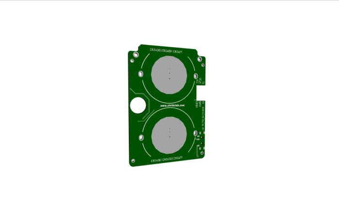
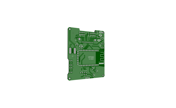
    0_1542056978541_20.png
    0_1542056983681_30.png
    The device has become thinner, less in height, all electronic components have been removed from the side of the batteries, and PCB have been prepared for mounting in the case.


  • @berkseo Thanks, very good modifications. I'll wait patiently 🙂 I'll then not use the 5 + 5 PC's and eait for the new ones.
    Do I understand you right, that I'll receive another 5 + 5 updated PCB's without additional money charged? That would be great (if required I can send you additional €'s or US$).
    Thanks for the font-hints. I'll test it once I'm back from my BIZ-trip.


  • @HEINZV Thanks for the clues. Now all modules are programmed in the Arduino IDE. Absolutely all modules - MySensors | Low power mode | programming in Arduino IDE | MySensors – 00:31
    — Andrew EfektaSB

    0_1542407959427_C35D45D6-CDED-4025-9EB8-08CEF07A2740.jpg

    Truth were nuances. Had to remove all the drivers for J-LINK, remove nRF GO. Then I installed the j-LINK Windows v640 drivers. Then again I installed nRF GO. And the most important point when installing nRF GO refuse to install drivers for J-LINK. nRF GO works with both my Chinese j-LINK clones 🙂


  • @berkseo glad to hear, that it worked.
    I'm meanwhile working on the sketch for the Tem & Hum sensor node. As written, I've switched to the GxEPD e-Paper library. It is easier to use and is installable via the Arduino Studio or via platform.io.
    I've evaluated a lot of fonts and have finally found one I like and which fits to the display even with the decimals. I used the fontconvert from the GxEPD lib which can convert any TTF or OTF font.
    Here is a picture (I'm still using the MySesnors PCB from ranseyer waiting for the new PCB's from you)
    0_1542660633767_20181119_213657_nRF52_Temp_Hum.jpg


  • @heinzv Finally got the PCB. Soon I will send the finished device.
    1_1543170753492_F436A79B-4D32-458F-BDBB-1CB435D7668B.jpg 0_1543170753492_805C0A8F-BB55-497D-B063-431C1D2E5687.jpg


  • @berkseo good to hear. And you also mentioned to send some new PCB'
    s? Let me know if I had to pay something additional.


  • The second revision of the device is ready, the tests are passed. Added cutouts and holes on the power Board for mounting in the case. Transferred inductance of the display (680), made a cut for her on the power PCB. All this slightly reduced the size of the device, now the size of 36mm x 52mm (old size 36mm x 54mm). The down-converter moves to the other side of the power PCB.
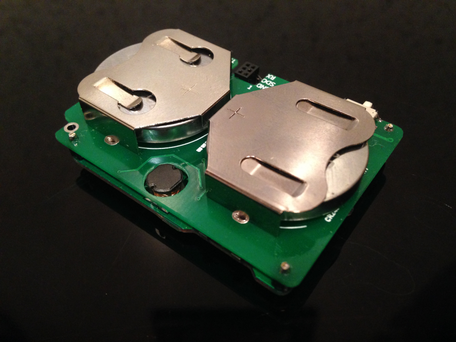
    0_1544833874820_IMG_3029.png


  • @heinzv The device and additional PCB are shipped.

    0_1544833499617_IMG_3043.png


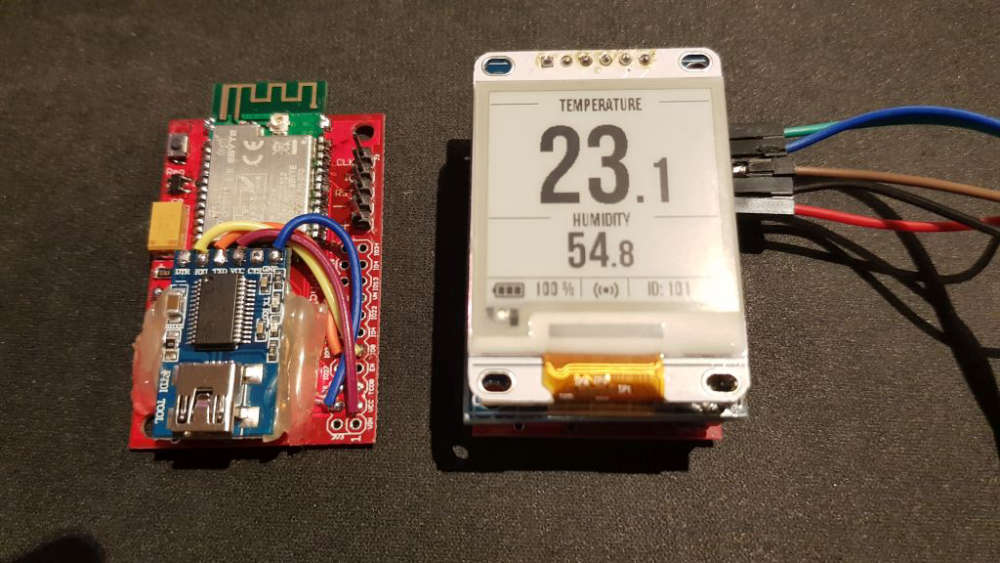
  • @berkseo looks very good, very professional work. I'll solder a few devices once I get the new PCB's and will also work further on my version of the firmware. It works already quite nice (transfering float values and showing decimals).
    Attached the picture of a working pair of a sensor node (using my PCB's) and a SHT31 and a nRF52 serial gateway.
    0_1545085203955_MySensors_nRF52832_Sensor_GatewaySerial.jpg


  • @berkseo I've got your Temp/Hum sensor today and the PCB's (3+3). Since I have ordered the cr2477 batteries and your batterholder takes only the cr2450, I've tried it with the program adapter and USB power. It works. Thanks. I have ordered now additional cr2450 batteries.
    I took the batteryholder form your list and they are for the cr2477!

    Then I soldered my own first two PCB's, the battery PCB and the Sensor PCB. It took me quite a while (3 hours at least). It's nothing for beginners (but I not a beginner 🙂 )
    However during my testing, I found my battery PCB working and the sensor node runs the MYSensors part and the LED blinks but the E-Paper does not work and also the SHT20 returns 998 for temp and hum.

    I have not found the C12 capacitor in your parts decription list, but only a C14 (which is not printed on the PCB) with 10uF. So I assumed the C12 = 10uF. I have seached the page and there is no C12.
    One the other hand, I have not found C14 on the new PCB. Maybe it's below C13 and no part print on PCB? The C13 is larger then the pads below, so it's confusing.
    Maybe you can update/correct it on openhwardware, so that I can solder it correct.

    So looking for the problems with e-paper and SHT20: A schematic diagram would really really help me, otherwise I'm lost. Please provide it (or at least via a PM?).
    Would it be possible to get it? If you have e.g. an Eagle project (schematics and board).

    It was really essential, that you provided the programm adapter for the tiny SWD connector. Thanks for that!

    here are my soldered PCB's:
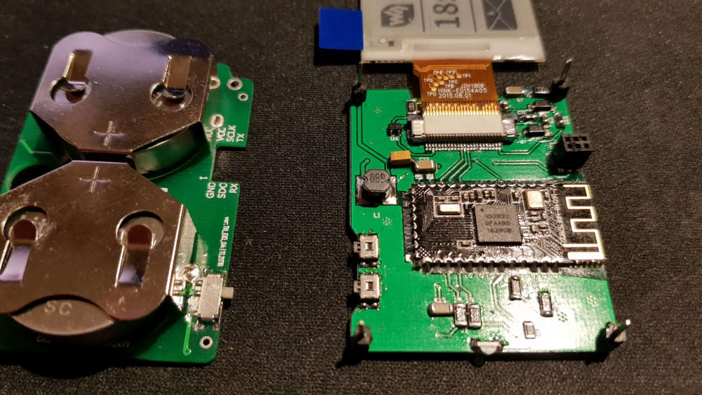
    0_1546041758749_EFEKTA_temp_hum-heinz-1.jpg


  • @heinzv said in 💬 EFEKTA Temp&Hum sensor(ver. nRF52832 )+E-Ink display:

    I've got your Temp/Hum sensor today and the PCB's (3+3). Since I have ordered the cr2477 batteries and your batterholder takes only the cr2450, I've tried it with the program adapter and USB power. It works. Thanks. I have ordered now additional cr2450 batteries.
    I took the batteryholder form your list and they are for the cr2477!
    Then I soldered my own first two PCB's, the battery PCB and the Sensor PCB. It took me quite a while (3 hours at least). It's nothing for beginners (but I not a beginner )
    However during my testing, I found my battery PCB working and the sensor node runs the MYSensors part and the LED blinks but the E-Paper does not work and also the SHT20 returns 998 for temp and hum.
    I have not found the C12 capacitor in your parts decription list, but only a C14 (which is not printed on the PCB) with 10uF. So I assumed the C12 = 10uF. I have seached the page and there is no C12. All capacitors are ceramic.
    One the other hand, I have not found C14 on the new PCB. Maybe it's below C13 and no part print on PCB? The C13 is larger then the pads below, so it's confusing.
    Maybe you can update/correct it on openhwardware, so that I can solder it correct.
    So looking for the problems with e-paper and SHT20: A schematic diagram would really really help me, otherwise I'm lost. Please provide it (or at least via a PM?).
    Would it be possible to get it? If you have e.g. an Eagle project (schematics and board).
    It was really essential, that you provided the programm adapter for the tiny SWD connector. Thanks for that!
    here are my soldered PCB's:

    There are 3 types of battery holders, I make ready-made devices only on 2450, it is optimal, 2477 very high, the device in the case turns out to be disproportionate.

    I solder for about half an hour:). Judging by the description of your problems, it's all about soldering. Solder the temperature sensor and the connector for the display should be a Hairdryer and solder paste. This is by the way perhaps the two most difficult procedures at home.

    C13 is a capacitor from 47mf to 200mf, I added it later. C14 is a 0.1 mf capacitor. C12 is a capacitor on the display inductance input, it should be from 4.7 mf to 10mf.

    Full schemes there is no, there is only parts of. I have this project done right in the program for PCB layout. But I understand that this is becoming a problem, and I will add the scheme to the project in the near future. Sorry, I know I should have done this a long time ago :((.

    You wrote a post last year :), I with the holidays just gave all that up. How you're doing now. Were you able to find a problem with the display and the temperature sensor?


  • @berkseo Happy new year! I was waiting for an answer from you, so I have not done any further investigation before I have more infos 😉
    I have now ordered another batch of 2450 battery holders (I have obviously clicket in the second link in your parts list which was the 2477).

    So based on your info, my C13 is definitly wrong, I have used a 0.1uF and need to change it to a 100uf (what are you using as you write 47uF to 200uF ?). I think I need to order them first. For C12 I used a 10uF so that fits.

    I think I could also have some problems with the 0.1uF parts as I have only the larger 1206 which I have to replace with 805 or 603 sized. I have ordered them already but you know that takes another 4-6weeks. So I'll wait till all parts are there and continue then with your infos and the correct ordered parts.

    I have also problems with my new script as my power consumption was first 0.8mA (800uA) and now it's even 3.1mA during sleep (on my other PCB's), but was following your sleep procedure (putting all internal and external devices to powerdown). I was expecting somewhat between 2 and 20uA, so I have to analyze what is wrong.

    So you solder your PCB in 0.5hour? Then I might order the PCB's bette rfrom you 🙂 It takes me at least 2+ hours (the first was 3hrs).
    I have a super small soldering iron and I also have a hot air SMD soldering station and quality solder paste. May I try it again with solder paste.

    more then later.

    thanks and bye till later
    Heinz


  • "L1, Inductance 4.7uh 1210 1 pcs", the text says 4.7uh but link goes to a store that sells 47uh. Which should it be?


  • @magpern

    Also replaced on the project page. Inductance on 4.7 was, apparently they ran out.


  • The project became closed. Reason: I previously placed links to all the necessary components for this device(see screenshot). This allowed me to earn quite a bit on the affiliate program. This allowed me a bit to recoup the costs, they are not small. The site administration considers this type of earnings unacceptable.

    0_1547813559311_Без имени.png


  • @berkseo Seriously!!!!!!!!!!!!! It cannot be true!!! I have just ordered PCBs and all needed stuff to assemble it, and now the code is gone!!! Please post the code again, or make it available on alternative sites.. please. It is hundreds of dollars to waste otherwise!


  • @magpern said in 💬 EFEKTA Temp&Hum sensor(ver. nRF52832 )+E-Ink display:

    Seriously!!!!!!!!!!!!! It cannot be true!!! I have just ordered PCBs and all needed stuff to assemble it, and now the code is gone!!! Please post the code again, or make it available on alternative sites.. please. It is hundreds of dollars to waste otherwise!

    The project will remain open, like others. I was in a bad mood that day:)... The rules of the site administration are reasonable, and the decision to open the project was mine.

    Code for Arduino IDE - https://drive.google.com/file/d/13wmxCt9XehJr1E2eyG1RnYsQTMb9A2LR/view?usp=sharing


  • @berkseo said in 💬 EFEKTA Temp&Hum sensor(ver. nRF52832 )+E-Ink display:

    @magpern said in 💬 EFEKTA Temp&Hum sensor(ver. nRF52832 )+E-Ink display:

    Seriously!!!!!!!!!!!!! It cannot be true!!! I have just ordered PCBs and all needed stuff to assemble it, and now the code is gone!!! Please post the code again, or make it available on alternative sites.. please. It is hundreds of dollars to waste otherwise!

    The project will remain open, like others. I was in a bad mood that day:)... The rules of the site administration are reasonable, and the decision to open the project was mine.

    Code for Arduino IDE - https://drive.google.com/file/d/13wmxCt9XehJr1E2eyG1RnYsQTMb9A2LR/view?usp=sharing

    Thank you! You scared me big time!
    Bad ting without links is that eg. clock button 2 pcs... there are millions of clock buttons and to pick the right one with out a link.. well, almost impossible.

    Thanks again!


  • @berkseo I have continued to work on the new PCB's und have oredered some 603 resistors und condensors. I have checked all of the parts and the soldering but did not get the one PCB to displays something. The program runs und I see the LED flashing and also the log looks normal.

    A build a second PCB and this one shows the intro graphics but with a grey background and then it stops showing something. No idea what goes wrong.

    0_1550531795687_20190219_000839.jpg


  • @heinzv
    I apologize that long did not answer. Did you solve the problem? I noticed that the inductance is small (it seemed to me). You should also check for solder connectors ribbon cable. Perhaps not all contacts are soldered and some contact lies on the PCB is not soldered. I had once, it was not well soldered contact pin on display connector .


  • Can you take me pictures in good resolution?


  • @berkseo no I have not solved the problem yet. I 'll take another picture with higher resolution tomorrow and post it here.
    The inductance has the value which is specifiied (I think 68uH). I have all ordered by the links provided.
    I have checked the soldering and resolved a few times. I think all pins shall be soldered, but I can verify it again. That was also my first thought and checked the ribbon cable over and over again.


  • @berkseo took a bit longer and I have now taken a picture with my Nikon Cam, not sure if it helps, I might add another one if required.
    But you see the inductor has 68uH.

    0_1551533389995_EFEKTA_Temp_Hum_DSC_1522.jpg


  • hey @berkseo these look amazing, any estimate when they might be available again as assembled unit?
    Any estimate on how long the battery lasts, with lats say update every 15min?
    Could these be updated OTA somehow (or directly perhaps)?
    I would like to have option to change layout, or perhaps add some other values to it maybe.
    They look amazing, I would like several of these in each room for various things displayed


  • @berkseo @heinzv I finally got around to solder one of these together. It was not easy, placing the components was kind of a guessing game, but I think I got it right. When I put two batteries in and turn it on there is a buzzing noise, maybe normal? Anyway... I never realized programming this thing would be a problem.

    What equipment is needed to program it? I don't recognize the labeling on the pcb (gnd/vcc sdo/sclk rx/tx)


  • @berkseo is the device programmed when output says this?

    Open On-Chip Debugger 0.10.0-dev-00254-g696fc0a (2016-04-10-10:13)
    Licensed under GNU GPL v2
    For bug reports, read
    	http://openocd.org/doc/doxygen/bugs.html
    debug_level: 0
    0x4000
    adapter speed: 10000 kHz
    nrf52.cpu: target state: halted
    target halted due to debug-request, current mode: Thread 
    xPSR: 0x01000000 pc: 0xfffffffe msp: 0xfffffffc
    ** Programming Started **
    auto erase enabled
    nrf52.cpu: target state: halted
    target halted due to breakpoint, current mode: Thread 
    xPSR: 0x61000000 pc: 0x2000001e msp: 0xfffffffc
    wrote 102400 bytes from file C:\Users\eu1391\AppData\Local\Temp\arduino_build_38086/epd1in54-demo.ino.hex in 2.178483s (45.904 KiB/s)
    ** Programming Finished **
    ** Verify Started **
    nrf52.cpu: target state: halted
    target halted due to breakpoint, current mode: Thread 
    xPSR: 0x61000000 pc: 0x2000002e msp: 0xfffffffc
    verified 100668 bytes in 0.296666s (331.378 KiB/s)
    ** Verified OK **
    ** Resetting Target **
    shutdown command invoked
    

    The only thing happening when I turn it on, is that the LED flashed once. Then occasionally the LED flashed sporadically.
    The e-paper is just white.

    Questions?
    Can you power the board from another source then the battery pcb?
    The board needs to be powered when programming it, right? I'm using a ST-LINK V2 with the SWD pins connected.
    How do you debug the board? I use Arduino IDE


  • It sure is lonely in here... but finally SUCCESS!!!!
    After days of googling and checking and rechecking the board for shorts, I found the problem. The 68uH was dead. Maybe damaged when soldering it. It did not conduct anything. After changing it to a new one, the display started working.
    0_1563229346799_2019-07-16 00.13.40.jpg
    Any idea how battery can be at 60% on more or less fresh batteries... anyway, that is another problem.

    I still have one question, if anyone can chip in that would be great.
    On the SWD connector it says, TX and RX, how do I use them?
    Or really what I mean, how do you debug the device? I use a ST-Link V2, but I am not getting any COM-port so I cannot start the serial debugger. Is the TX/RX used for the serial debugging? Can I use ST-Link V2 for this or do I need a separate device?
    I have tried to change the driver with ZADIG, but still no COM-port. As for now I have only connected 4 of the 6 pins in the SWD.

    Please @berkseo help me!


  • @magpern said in 💬 EFEKTA Temp&Hum sensor(ver. nRF52832 )+E-Ink display:

    is the device programmed when output says this?

    yes


  • @magpern said in 💬 EFEKTA Temp&Hum sensor(ver. nRF52832 )+E-Ink display:

    Any idea how battery can be at 60% on more or less fresh batteries... anyway, that is another problem.

    Calculate the resistor divider. It is on the power Board. Perhaps you have mixed up resistors.


  • @magpern said in 💬 EFEKTA Temp&Hum sensor(ver. nRF52832 )+E-Ink display:

    On the SWD connector it says, TX and RX, how do I use them?

    Via TTL Converter. The program must be enabled in the debug.


  • @berkseo said in 💬 EFEKTA Temp&Hum sensor(ver. nRF52832 )+E-Ink display:

    TTL Converter.

    Thanks! I found in another thread one could use a FTDI, I will try that!


  • @magpern said in 💬 EFEKTA Temp&Hum sensor(ver. nRF52832 )+E-Ink display:

    Can I use ST-Link V2 for this or do I need a separate device?

    You can connect the programmer and TTL Converter at the same time. You can also do so - https://translate.google.ru/translate?hl=&sl=ru&tl=en&u=https%3A%2F%2Fmysensors-rus.github.io%2Ftroubleshooting_on_Cortex_MCU_in_Arduino%2F


  • @magpern any USB2COM of your choice 🙂


  • @magpern Very neatly done!


  • @berkseo Thanks! Hopefully I can finish my project of automating my radiators. Project has been ongoing for many years.

    Btw, any chance you could upload the gerber for the newest version of the board, the one with the inductor placed more centered on the board and with a hole in the power board? I see now the boards sandwich better if the hole is there.
    (and ofcourse of you have a newer version of the code, that too)


  • @berkseo
    Good looking device that you have created originally 🙂


  • Edit: After I posted this the device has worked for 2 days. But still, the capasitors are they correct?

    @berkseo I have a wierd problem with the SHT20 sensor. It stops working after a few reads. Then the device hangs and goes into battery draining mode with atleast 8mA constant current. I have localized it to the SHT20, because if I comment out the init and read temp/humidity of the SHT20 the device boots up.
    The wierdest is that the SHT20 stops responding for quite some time, even if I power cycle the device, it is still not responding.
    Last night I had it running for 1 hour, powered with 3.3V directly. Turned power of, had some sleep, turned power on SHT20 not responding. Turned power of, played with the kids, 3 hours later turned power on, the SHT20 is now responding. Now it's been going for 20 minutes and is still responding. But I bet if I let it run, it will stop.

    I am fairly sure the SHT20 is soldered to the board correctly. I used reflow (heatgun) and solder paste was liquid and I could poke the SHT20 and it popped back automatically by surface tension.
    I have also tried to replace the SHT20, but the result is the same. the device when hung)

    Anything you recognize?

    I have not yet successfully been able to debug the device, if i compile with the MY_DEBUG active, the device does not come on and the led shines constantly and I'm not sure how to connect the FTDI, should Vcc on the SWD provide power or not?

    I have checked the capasitors C12, C13 and C14 since they have been talked about before and differ from the BOM list and the real board.
    C12 is 10uF
    C13 is 100uF (100uF is very big, only had a 1206 size, but I got it in place, will get 47uF 0805 for next iteration, waiting for a solder paste dispenser from China)
    C14 is 100nF


  • @berkseo i have 2 questions regarding your device:

    1. Is it possible to add some additional sensors or are no UARTs left?
      I would like to add an accelerometer and 2-4 capacitive touch sensors.

    2. Where can I order the PCBs or an assembled version, because the order links on open hardware.io aren't working anymore. Get only the eBay startpage.


  • @magpern I think that perhaps the problem with the i2c bus. The revision of the chip. Try to disconnect the bus before going to bed and then initialize again.


  • @lexusburn

    1.I do not plan to add anything to this project. he as there is. Just an evaluation module.
    2. The sources for the order are attached to the project on openhardware. Assembled modules I do not sell now, too lazy to solder them.

    ...Logical continuation of this project:
    E-paper_2.13 nRF52840 bme280 Mysensors | Zigbee – 00:45
    — Andrew EfektaSB

    0_1570779751139_IMG_20190810_190151.jpg


  • Hi, everybody. A new version of the device(V3) is currently being tested. Now this device is in its own case. Works on MCU nRF52810, nRF52811, (in sleep mode 2μA) NRF 52832 (sleep 3.7μA) and nRF52840 (sleep 4.7μA). Power from 2x2450 or 2x2477. There will be an update soon on openhardware.io.
    IMG_20200503_153155.jpg IMG_20200503_153220.jpg IMG_20200503_153251.jpg IMG_20200503_154842_789.jpg


  • IMG_20200527_225341.jpg IMG_20200527_230629.jpg IMG_20200527_231155.jpg


  • Hi,

    @berkseo , do you use image2lcd to convert image to .c ?
    With what parameters ?

    Thanks.

    Ikes


  • prototype e-ink1.54 V4, even smaller, even faster 🙂
    GDEH0154D67 + nRF52832 First SW test. – 01:25
    — Andrew EfektaSB


  • @berkseo, thanks.
    Finally, I found another solution with image2cpp, that allow direct conversion of svg files.

    link text

    So i can convert icons from [link text] (https://iconify.design/icon-sets/mdi/)

    alt text

    And for fonts, i use link text, it works fine with Gxepd2 library.


  • Update on the project. New version added to openhardware.io


Suggested Topics

  • 13
  • 2
  • 2
  • 1
  • 1
  • 9
  • 210
  • 12

0
Online

11.4k
Users

11.1k
Topics

112.7k
Posts