Back to Basics - Arduino MEGA + NRF24+LNA + W5100 Shield
-
Hi Folks,
After my last little brain implosion, I've decided to go back to basics.
I've completely rebuilt my gatewayNode from the ground up, and included the current sketch below.
When I run the serial monitor on the bench, i get a slow "eth failed" message, which I expect (sadly I don't have Ethernet connection at my outdoor workspace) and when I plug it into the router (both USB to power the unit and eth) I get an "eth failed" message approx 4 times a second, but I can PING the address.
I can't add the gateway to MyController, it just times out.
I am powering the radio directly from the 3v pin on the mega, (no cap as I don't have any here) and there is nothing other than the LED indicators plugged into it.
I'm just trying to work out where I should START looking, before i go back to pulling my hair out!
Any advice greatly appreciated!
/** * NRF24/Ethernet Gateway Node - v0.1 */ // Enable debug prints to serial monitor #define MY_DEBUG // Pin Confuguration for Arduino Mega #define MY_RF24_CE_PIN 49 #define MY_RF24_CS_PIN 53 // Radio type #define MY_RADIO_NRF24 // Ethernet module type #define MY_GATEWAY_W5100 // MAC Address #define MY_MAC_ADDRESS 0xDE, 0xAD, 0xBE, 0xEF, 0xFE, 0xED // Enable MY_IP_ADDRESS here if you want a static ip address (no DHCP) #define MY_IP_ADDRESS 10,0,0,201 #define MY_IP_GATEWAY_ADDRESS 10,0,0,1 #define MY_IP_SUBNET_ADDRESS 255,255,255,0 // Listening Port #define MY_PORT 5003 // MyController IP Address #define MY_CONTROLLER_IP_ADDRESS 10,0,0,200 // Enable inclusion mode #define MY_INCLUSION_MODE_FEATURE // Enable Inclusion mode button on gateway //#define MY_INCLUSION_BUTTON_FEATURE // Set inclusion mode duration (in seconds) #define MY_INCLUSION_MODE_DURATION 60 // Digital pin used for inclusion mode button //#define MY_INCLUSION_MODE_BUTTON_PIN 3 // Set blinking period #define MY_DEFAULT_LED_BLINK_PERIOD 300 // Flash leds on rx/tx/err #define MY_DEFAULT_ERR_LED_PIN 22 // Error led pin #define MY_DEFAULT_RX_LED_PIN 26 // Receive led pin #define MY_DEFAULT_TX_LED_PIN 24 // Transmit led pin #include <Ethernet.h> #include <MySensors.h> void setup() { // Setup locally attached sensors } void presentation() { // Present locally attached sensors here } void loop() { // Send locally attached sensors data here } -
@zachflem do you have more than one W5100 running at home? All W5100 need to have a unique mac address.
Could ypu post the full debug log?
Evening @mfalkvidd
do you have more than one W5100 running at home? All W5100 need to have a unique mac address.
This is the only one currently. I'm aware of the need for unique MAC addresses and have a schema in place to cover this.
Could ypu post the full debug log?
Sure! This is the first 3 bursts that appear, anything after this just increases the TSM:FAIL:CNT=X count
I'm not even getting the ETH:FAIL errors now =(
0 MCO:BGN:INIT GW,CP=RNNGA---,VER=2.2.0 3 TSM:INIT 4 TSF:WUR:MS=0 11 !TSM:INIT:TSP FAIL 13 TSM:FAIL:CNT=1 14 TSM:FAIL:DIS 16 TSF:TDI:TSL 10018 TSM:FAIL:RE-INIT 10020 TSM:INIT 10028 !TSM:INIT:TSP FAIL 10030 TSM:FAIL:CNT=2 10032 TSM:FAIL:DIS 10034 TSF:TDI:TSL 20036 TSM:FAIL:RE-INIT 20038 TSM:INIT 20045 !TSM:INIT:TSP FAIL 20047 TSM:FAIL:CNT=3 20049 TSM:FAIL:DIS 20051 TSF:TDI:TSL -
Evening @mfalkvidd
do you have more than one W5100 running at home? All W5100 need to have a unique mac address.
This is the only one currently. I'm aware of the need for unique MAC addresses and have a schema in place to cover this.
Could ypu post the full debug log?
Sure! This is the first 3 bursts that appear, anything after this just increases the TSM:FAIL:CNT=X count
I'm not even getting the ETH:FAIL errors now =(
0 MCO:BGN:INIT GW,CP=RNNGA---,VER=2.2.0 3 TSM:INIT 4 TSF:WUR:MS=0 11 !TSM:INIT:TSP FAIL 13 TSM:FAIL:CNT=1 14 TSM:FAIL:DIS 16 TSF:TDI:TSL 10018 TSM:FAIL:RE-INIT 10020 TSM:INIT 10028 !TSM:INIT:TSP FAIL 10030 TSM:FAIL:CNT=2 10032 TSM:FAIL:DIS 10034 TSF:TDI:TSL 20036 TSM:FAIL:RE-INIT 20038 TSM:INIT 20045 !TSM:INIT:TSP FAIL 20047 TSM:FAIL:CNT=3 20049 TSM:FAIL:DIS 20051 TSF:TDI:TSLTSM:INIT:TSP FAILmeans the nrf24 could not be initialized. The most common cause is miswiring or "wrong" pins defined.
The defines in your sketch look good to me.
Could you post a photo of your wiring? Sometimes it helps to get a new pair of eyes on it. Try to take a photo (or multiple) so each wire can be traced from start to finish.
-
TSM:INIT:TSP FAILmeans the nrf24 could not be initialized. The most common cause is miswiring or "wrong" pins defined.
The defines in your sketch look good to me.
Could you post a photo of your wiring? Sometimes it helps to get a new pair of eyes on it. Try to take a photo (or multiple) so each wire can be traced from start to finish.
-
I've got the following:
3v-----------RED------------V+
GND-------BROWN------GND
49----------WHITE--------CE
50----------PURPLE------MISO
51----------BLUE-----------MOSI
52----------GREEN--------SCK
53----------BLACK--------CSN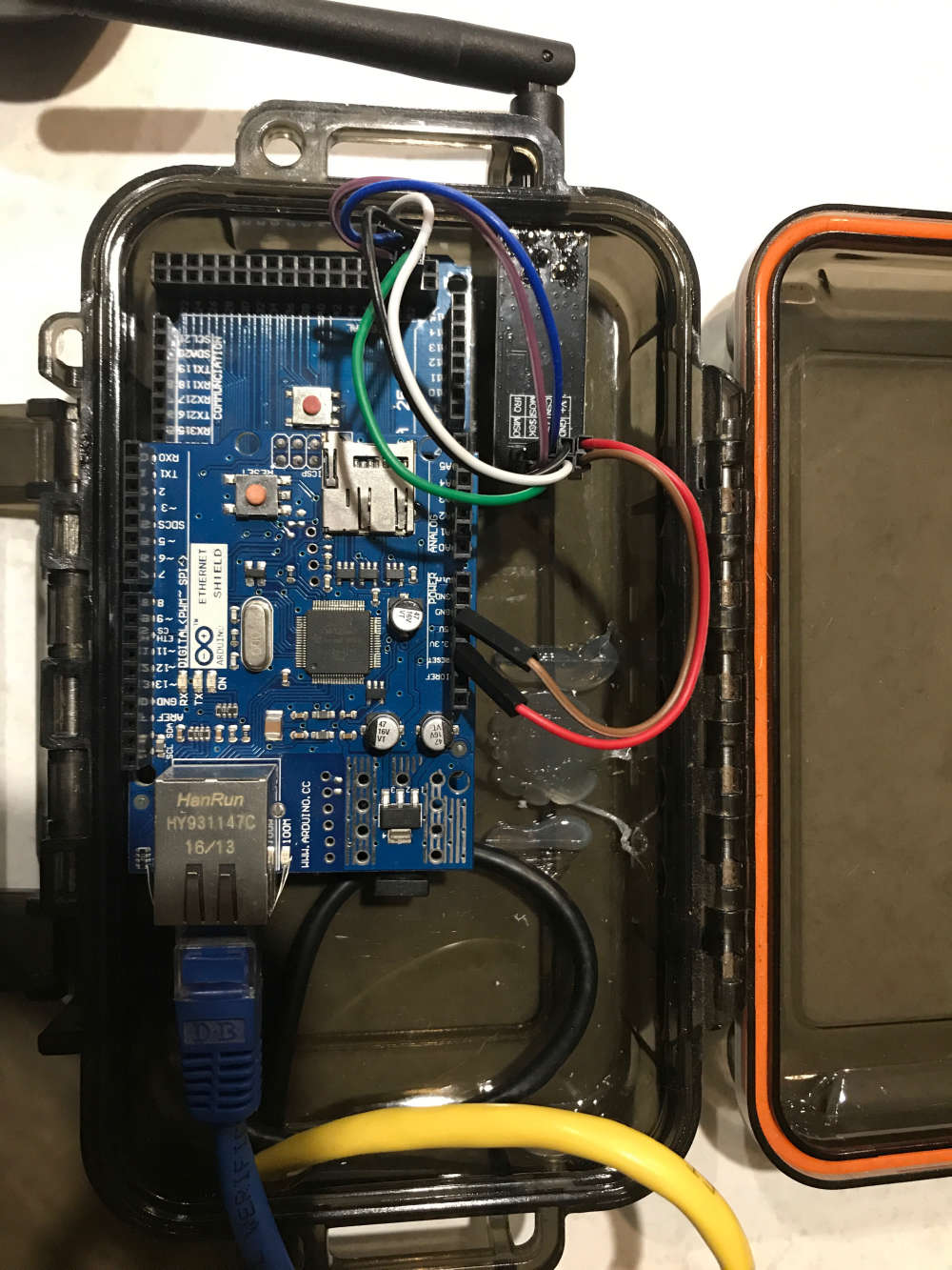
-
@zachflem I can't tell from the picture where the blue, white and purple wires are connected to the mega, but except that it looks good. Nice case.
@mfalkvidd the blue, white and purple are 100% as per my wiring description. Might it have something to do with not having the cap on the power?
I'm at a loss as to what is going wrong here...
The case is a AUD$10 waterproof unit (before i drilled holes in the side of it) from Bunnings: https://goo.gl/kzDaZi
I've also got a bigger (AUD$16) version housing a bigger project: https://goo.gl/zgvd7h
-
@mfalkvidd the blue, white and purple are 100% as per my wiring description. Might it have something to do with not having the cap on the power?
I'm at a loss as to what is going wrong here...
The case is a AUD$10 waterproof unit (before i drilled holes in the side of it) from Bunnings: https://goo.gl/kzDaZi
I've also got a bigger (AUD$16) version housing a bigger project: https://goo.gl/zgvd7h
Hello! It looks like you're interested in this conversation, but you don't have an account yet.
Getting fed up of having to scroll through the same posts each visit? When you register for an account, you'll always come back to exactly where you were before, and choose to be notified of new replies (either via email, or push notification). You'll also be able to save bookmarks and upvote posts to show your appreciation to other community members.
With your input, this post could be even better 💗
Register Login