Adding sensor to controller when it's part of gateway
-
G'day everyone
I'm trying to merge some of my sensors so I can save a little money. I know I'm not going to save much, but every dollar counts lol anyways what I've done is merged my RF433 Hub with my Ethernet gateway. My Vera controller seems to see the gateway, but how do I get it to see the child devices of the hub?
-
I have been working on this for most of the day, but haven't got far :-(
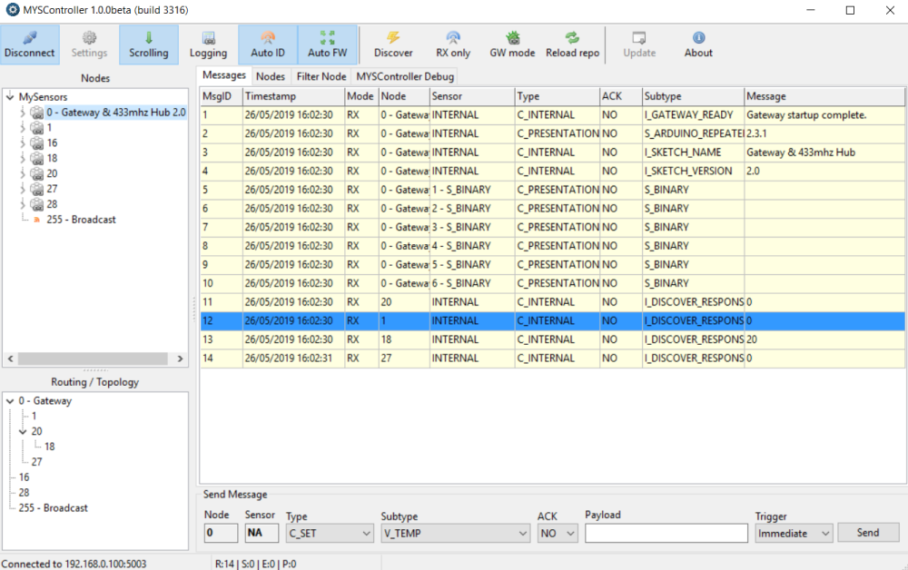
A search found that I am not the only person to experience this issue, but unfortunately I couldn't find a fix. I found this thread where someone was having the exact same issue, so I did what it was suggested and downloaded MYSController and followed the instructions. MYSController showed me some cool stuff, and it seems to see that I have created 6 RF433 devices, but I don't know what to do to make them show up on my Vera controller.
Below is a screenshot of MYSController. There are no sensors attached in any way to the Gateway, apart from the 6 RF433 devices that I created in the sketch.
In case it's the sketch where I made the mistake, I will include it below. I have read through it over and over and I just can't seem to find why the sensors won't show up.
// Enable debug prints to serial monitor
#define MY_DEBUG

// Enable and select radio type attached
#define MY_RADIO_RF24
//#define MY_RADIO_NRF5_ESB
//#define MY_RADIO_RFM69
//#define MY_RADIO_RFM95

// Enable gateway ethernet module type
#define MY_GATEWAY_W5100

// W5100 Ethernet module SPI enable (optional if using a shield/module that manages SPI_EN signal)
//#define MY_W5100_SPI_EN 4

// Enable Soft SPI for NRF radio (note different radio wiring is required)
// The W5100 ethernet module seems to have a hard time co-operate with
// radio on the same spi bus.
#if !defined(MY_W5100_SPI_EN) && !defined(ARDUINO_ARCH_SAMD)
#define MY_SOFTSPI
#define MY_SOFT_SPI_SCK_PIN 14
#define MY_SOFT_SPI_MISO_PIN 16
#define MY_SOFT_SPI_MOSI_PIN 15
#endif

// When W5100 is connected we have to move CE/CSN pins for NRF radio
#ifndef MY_RF24_CE_PIN
#define MY_RF24_CE_PIN 5
#endif
#ifndef MY_RF24_CS_PIN
#define MY_RF24_CS_PIN 6
#endif

// Enable UDP communication
//#define MY_USE_UDP  // If using UDP you need to set MY_CONTROLLER_IP_ADDRESS or MY_CONTROLLER_URL_ADDRESS below

// Enable MY_IP_ADDRESS here if you want a static ip address (no DHCP)
#define MY_IP_ADDRESS 192,168,0,100

// If using static ip you can define Gateway and Subnet address as well
//#define MY_IP_GATEWAY_ADDRESS 192,168,0,100
//#define MY_IP_SUBNET_ADDRESS 255,255,255,0

// Renewal period if using DHCP
//#define MY_IP_RENEWAL_INTERVAL 60000

// The port to keep open on node server mode / or port to contact in client mode
#define MY_PORT 5003

// How many clients should be able to connect to this gateway (default 1)
#define MY_GATEWAY_MAX_CLIENTS 8

// Controller ip address. Enables client mode (default is "server" mode).
// Also enable this if MY_USE_UDP is used and you want sensor data sent somewhere.
//#define MY_CONTROLLER_IP_ADDRESS 192, 168, 178, 254
//#define MY_CONTROLLER_URL_ADDRESS "my.controller.org"

// The MAC address can be anything you want but should be unique on your network.
// Newer boards have a MAC address printed on the underside of the PCB, which you can (optionally) use.
// Note that most of the Arduino examples use  "DEAD BEEF FEED" for the MAC address.
#define MY_MAC_ADDRESS 0xDE, 0xAD, 0xBE, 0xEF, 0xFE, 0xED


// Enable inclusion mode
#define MY_INCLUSION_MODE_FEATURE
// Enable Inclusion mode button on gateway
//#define MY_INCLUSION_BUTTON_FEATURE
// Set inclusion mode duration (in seconds)
#define MY_INCLUSION_MODE_DURATION 60
// Digital pin used for inclusion mode button
//#define MY_INCLUSION_MODE_BUTTON_PIN  3

// Set blinking period
#define MY_DEFAULT_LED_BLINK_PERIOD 300

// Flash leds on rx/tx/err
// Uncomment to override default HW configurations
//#define MY_DEFAULT_ERR_LED_PIN 7  // Error led pin
//#define MY_DEFAULT_RX_LED_PIN  8  // Receive led pin
//#define MY_DEFAULT_TX_LED_PIN  9  // Transmit led pin

#if defined(MY_USE_UDP)
#include <EthernetUdp.h>
#endif
#include <Ethernet.h>
#include <SPI.h>
#include <MySensors.h>
#include <RCSwitch.h>


#define NUMBER_OF_PLUGS 6 // Total number of attached plugs

#define SHORTPULSE 316
#define LONGPULSE 818

#define CODE_1On 4072574
#define CODE_1Off 4072566
#define CODE_2On 4072572
#define CODE_2Off 4072564
#define CODE_3On 4072570
#define CODE_3Off 4072562
#define CODE_4On 1386894
#define CODE_4Off 1386886
#define CODE_5On 1386892
#define CODE_5Off 1386884
#define CODE_6On 1386890
#define CODE_6Off 1386882

RCSwitch mySwitch = RCSwitch();

void setup()
{
  mySwitch.enableTransmit(4);
  mySwitch.setRepeatTransmit(15);
}

void presentation()
{
  // Send the sketch version information to the gateway and Controller
  sendSketchInfo("Gateway & 433mhz Hub", "2.0");

  for (int sensor = 1 ; sensor <= NUMBER_OF_PLUGS; sensor++) {
    // Register all sensors to gw (they will be created as child devices)
    present(sensor, S_LIGHT);
  }
}

void loop()
{
  // Send locally attached sensors data here
}

void receive(const MyMessage &message) {
  // We only expect one type of message from controller. But we better check anyway.
  if (message.type == V_LIGHT) {
    int incomingLightState =  message.getBool();
    int incomingOutlet = message.sensor;

    Serial.print("Outlet #: ");
    Serial.println(message.sensor);
    Serial.print("Command: ");
    Serial.println(message.getBool());

    if (incomingOutlet == 1) {
      if (incomingLightState == 1) {
        // Turn on  socket 1
        Serial.println("Turn on Socket 1");
        mySwitch.send(CODE_1On, 24); // These codes are unique to each outlet
        delay(50);
      }
      if (incomingLightState == 0)  {
        // Turn off socket 1
        Serial.println("Turn off Socket 1");
        mySwitch.send(CODE_1Off, 24);
        delay(50);
      }
    }
    if (incomingOutlet == 2) {
      if (incomingLightState == 1) {
        // Turn on  socket 2
        Serial.println("Turn on Socket 2");
        mySwitch.send(CODE_2On, 24);
        delay(50);
      }
      if (incomingLightState == 0)  {
        // Turn off socket 2
        Serial.println("Turn off Socket 2");
        mySwitch.send(CODE_2Off, 24);
        delay(50);
      }
    }
    if (incomingOutlet == 3) {
      if (incomingLightState == 1) {
        // Turn on  socket 3
        Serial.println("Turn on Socket 3");
        mySwitch.send(CODE_3On, 24);
        delay(50);
      }
      if (incomingLightState == 0)  {
        // Turn off socket 3
        Serial.println("Turn off Socket 3");
        mySwitch.send(CODE_3Off, 24);
        delay(50);
      }
    }
    if (incomingOutlet == 4) {
      if (incomingLightState == 1) {
        // Turn on  socket 4
        Serial.println("Turn on Socket 4");
        mySwitch.send(CODE_4On, 24);
        delay(50);
      }
      if (incomingLightState == 0)  {
        // Turn off socket 4
        Serial.println("Turn off Socket 4");
        mySwitch.send(CODE_4Off, 24);
        delay(50);
      }
    }
    if (incomingOutlet == 5) {
      if (incomingLightState == 1) {
        // Turn on  socket 5
        Serial.println("Turn on Socket 5");
        mySwitch.send(CODE_5On, 24);
        delay(50);
      }
      if (incomingLightState == 0)  {
        // Turn off socket 5
        Serial.println("Turn off Socket 5");
        mySwitch.send(CODE_5Off, 24);
        delay(50);
      }
    }
    if (incomingOutlet == 6) {
      if (incomingLightState == 1) {
        // Turn on  socket 6
        Serial.println("Turn on Socket 6");
        mySwitch.send(CODE_6On, 24);
        delay(50);
      }
      if (incomingLightState == 0)  {
        // Turn off socket 6
        Serial.println("Turn off Socket 6");
        mySwitch.send(CODE_6Off, 24);
        delay(50);
      }
    }
  }
  delay(50);
}
I am guessing from the thread that I linked to, that there is something I can do from within MYSController to have the child devices show up; am I right?
Looking forward to hearing back from someone! I currently have the flu and I am sick of being in bed and resting! :-)
-
@homer You talk about RF433 devices and yet you...
#define MY_RADIO_RF24
Maybe that is where the problem lies? I am not sure though as I haven't done anything the way you are.
@skywatch I appreciate your response!
You can ignore any reference to rf433 devices. All I've really done is created a sensor within the gateway sketch. That sensor happens to control 6 rf433 plugs, that's all.
So what I have is my Arduino Uno with Ethernet setup as the standard gateway but I've added the sensor to the sketch, and I can't seem to add the sensor part to my controller. The windows program MYSController sees everything on the gateway including the sensor; I just need to know how to get my controller to see it.
-
@Homer I am no expert in this but I have thought of something that you could try.
If I understand correctly you have added one RF433 transmitter to the GW node? This then sends data (On/Off) to the 6 RF433 sockets.
If so then the gateway only has one child, the RF433 transmitter, the sockets are not 'attached' to the GW.
So instead of presenting all 6 sockets, just present the one RF433 transmitter and see if that helps? All the code for the actions is in the receive section anyway.
This is how I did it with IR blaster and it works fine, changing IR for RF should not make a difference in the structure.
Hold on - I think I got it.....!!!!
You are using S_LIGHT in presentation - that is no longer supported.
Change S_LIGHT to S_BINARY.
Another thing is that although you are presenting your child(s), you do not define the type. I would expect a MyMessage in there somewhere at the start.
So add MyMessage msgyourmessage (child_id, V_STATUS);
And finally change V_LIGHT to V_STATUS in the receive function.
@skywatch said in Adding sensor to controller when it's part of gateway:
@Homer I am no expert in this but I have thought of something that you could try.
If I understand correctly you have added one RF433 transmitter to the GW node? This then sends data (On/Off) to the 6 RF433 sockets.
If so then the gateway only has one child, the RF433 transmitter, the sockets are not 'attached' to the GW.
So instead of presenting all 6 sockets, just present the one RF433 transmitter and see if that helps? All the code for the actions is in the receive section anyway.
This is how I did it with IR blaster and it works fine, changing IR for RF should not make a difference in the structure.
Hold on - I think I got it.....!!!!
You are using S_LIGHT in presentation - that is no longer supported.
Change S_LIGHT to S_BINARY.
Another thing is that although you are presenting your child(s), you do not define the type. I would expect a MyMessage in there somewhere at the start.
So add MyMessage msgyourmessage (child_id, V_STATUS);
And finally change V_LIGHT to V_STATUS in the receive function.
Thanks! Yes, you got it lol!!
The thing that is weird is that all I did was add the rf433 controlled devices from a working sketch to the gateway sketch, so why does it work when it's separate but not when it's part of the gateway sketch? If S_LIGHT is no longer supported, why does it work on a standalone sensor?
Hello! It looks like you're interested in this conversation, but you don't have an account yet.
Getting fed up of having to scroll through the same posts each visit? When you register for an account, you'll always come back to exactly where you were before, and choose to be notified of new replies (either via email, or push notification). You'll also be able to save bookmarks and upvote posts to show your appreciation to other community members.
With your input, this post could be even better 💗
Register Login