Piezzo siren/alarm

-
@fotofieber hi thank you for your message
I was coming back here to share my findings.... been playing with... ToneAC :joy:
Yes you're right, differential drive makes a hell of a difference! each pin of the piezo speaker are connected to its own arduino output (serial resistor on one pin though) that send the same signal in opposition as to get a differential movment.
But i don't quite get it :
- driving the piezo speaker with up to 25V doesn't improve noise level at all
- switching to differential drive @5V (so it's a 10V potential peak-to-peak) opens hell's doors wide open
That's the part i dont understand. I'll carry on investigating.
Still: noise level is a bit below as compared to same pizeo speaker connected to original alarm enclosure...
I might have a go with transistors and try a differential of 2S or 3S LiPo.
Also waiting for my oscilloscope to find out!And lastly: ToneAC uses pins 9 and 10... so it's a NO-NO with nRF24 :cry:
Enters... ToneAC2. It's inferior (CPU cycle, accuracy, lower freq) in many points except that pins are configurable.More soon... :nerd_face:
@ben999 said in Piezzo siren/alarm:
But i don't quite get it :
driving the piezo speaker with up to 25V doesn't improve noise level at all
switching to differential drive @5V (so it's a 10V potential peak-to-peak) opens hell's doors wide openYou may try to use a 1kOhm resistor parallel to the piezo (as suggested on eevblog).
-
@ben999 nice work, thanks for sharing.
To change pins for the nrf24, use the following in your sketch
#define MY_RF24_CE_PIN 7 #define MY_RF24_CS_PIN 8@mfalkvidd oh yeah I forgot about that one!!! Thanks a lot! I have used this with a Mega for who-knows-what-reason in the past but completely forgot about it! ToneAC still in the race then, thanks again
@fotofieber thanks a lot, but that thread is for high-level hobbyists!!! :scream: Schematics, yummy!!!
"replace the resistor with an inductor then you double the swing" but no figures... i'll google that and see where it gets me...
I dont even know the specs of my piezo :zipper_mouth_face: -
@mfalkvidd oh yeah I forgot about that one!!! Thanks a lot! I have used this with a Mega for who-knows-what-reason in the past but completely forgot about it! ToneAC still in the race then, thanks again
@fotofieber thanks a lot, but that thread is for high-level hobbyists!!! :scream: Schematics, yummy!!!
"replace the resistor with an inductor then you double the swing" but no figures... i'll google that and see where it gets me...
I dont even know the specs of my piezo :zipper_mouth_face:@ben999 said in Piezzo siren/alarm:
@fotofieber thanks a lot, but that thread is for high-level hobbyists!!! Schematics, yummy!!!
"replace the resistor with an inductor then you double the swing" but no figures... i'll google that and see where it gets me...
I dont even know the specs of my piezoI try to simplify: Take a 1 kOhm resistor and attach each side of it to another pin of the piezo. Don't change anything else.
-
@ben999 said in Piezzo siren/alarm:
@fotofieber thanks a lot, but that thread is for high-level hobbyists!!! Schematics, yummy!!!
"replace the resistor with an inductor then you double the swing" but no figures... i'll google that and see where it gets me...
I dont even know the specs of my piezoI try to simplify: Take a 1 kOhm resistor and attach each side of it to another pin of the piezo. Don't change anything else.
@fotofieber :grin: oh yes i got that one correct :stuck_out_tongue_winking_eye:
It was more about how to size the inductor and stuff. Guys on these forums know their sh*t, they dont go into much details: "just stick a thing there and you'll be good" :joy:
-
Guys,
Thanks all a lot for your input.
Seems sorted :
- differential drive (ToneAC)
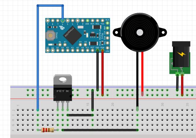
- transistor (TIP120 in my case, not sure it's my best move)
- 3S louder than 2S, itself louder than 1S
Schematic TIP120 and 1k resistors
I did also put a 1k resistor in between the piezo speaker pins... but it lowered the tone by quite a lot... :thinking_face:To be tested
I'll have a go with an inductance to see what " then you double the swing" means... double the loudness or double the speed ?
Thanks again, people involved :wink:
-
Guys,
Thanks all a lot for your input.
Seems sorted :
- differential drive (ToneAC)
- transistor (TIP120 in my case, not sure it's my best move)
- 3S louder than 2S, itself louder than 1S
Schematic TIP120 and 1k resistors
I did also put a 1k resistor in between the piezo speaker pins... but it lowered the tone by quite a lot... :thinking_face:To be tested
I'll have a go with an inductance to see what " then you double the swing" means... double the loudness or double the speed ?
Thanks again, people involved :wink:
@ben999 said in Piezzo siren/alarm:
I did also put a 1k resistor in between the piezo speaker pins... but it lowered the tone by quite a lot..
Cool, you sorted it out! The resistor may only help in an DC setup (one output from the arduino). In your AC setup it is useless.
-
@ben999 said in Piezzo siren/alarm:
I did also put a 1k resistor in between the piezo speaker pins... but it lowered the tone by quite a lot..
Cool, you sorted it out! The resistor may only help in an DC setup (one output from the arduino). In your AC setup it is useless.
@fotofieber gosh that a good analysis :+1: that makes a lot of sense
Then i can picture things better:- one output with 0 et +5V is considered as DC
- two output pulling differentially -5V to +5V... looks like a sin curbe... so it's AC !
Breadboard is out and still cabled, i'll have a go asap and confirm
Thanks again for your knowledge
-
@fotofieber gosh that a good analysis :+1: that makes a lot of sense
Then i can picture things better:- one output with 0 et +5V is considered as DC
- two output pulling differentially -5V to +5V... looks like a sin curbe... so it's AC !
Breadboard is out and still cabled, i'll have a go asap and confirm
Thanks again for your knowledge
@ben999
You could try DC (one output) with 12V to the piezo. If you want to use only 5V, the AC solution should be louder, as it gets 10V difference to the piezo.I usually stop optimizing, when it is good enough. If AC is enough, go with it. :)
-
@ben999
You could try DC (one output) with 12V to the piezo. If you want to use only 5V, the AC solution should be louder, as it gets 10V difference to the piezo.I usually stop optimizing, when it is good enough. If AC is enough, go with it. :)
@fotofieber DC+ one output is really poor and voltage has no impact on noise. I have tested with up to 6S LiPo and there's absolutely no gain as compared to 5V DC
AC+ two outputs is a game changer! Much louder right from +/-5V and really a killer @ +/-12V.
So that's it: the first iteration of this project will go for a step-up converter from 5V up to 12V for the piezo speaker.
Thanks folks!
EDIT: could someone suggest a MOSFET (or transistor) that could be used in lieu of the huge (and probably over-sized) TIP120 (that where there, waiting in the drawer :) ). Through-hole is my league. SMD is a bit of a struggle (welding, machining pcb, ...)
Thanks again :smiley:
-
back at it !
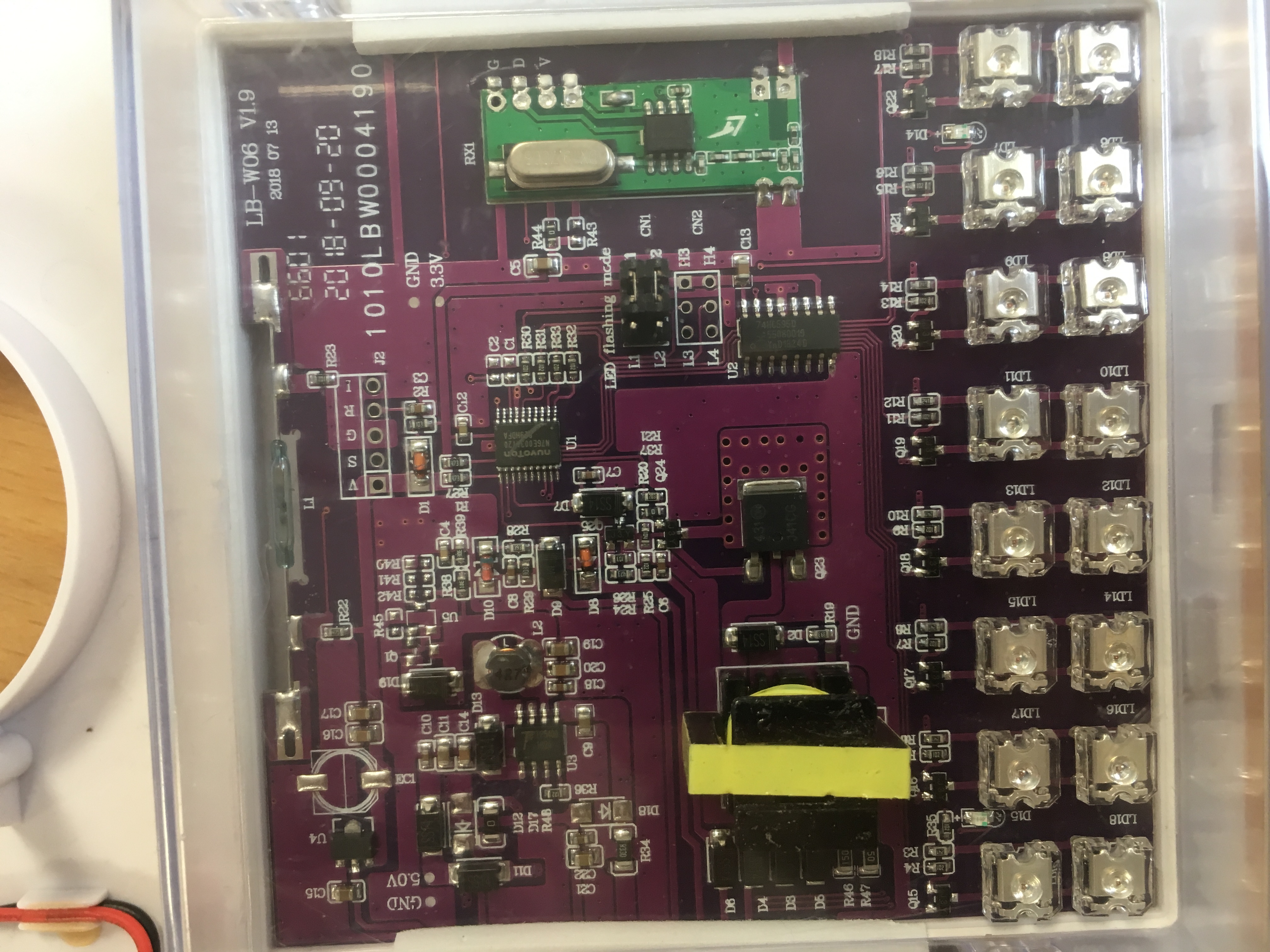
I got my LCD microscope out and tried to reverse-engineer the original board. I should have done that to start with.
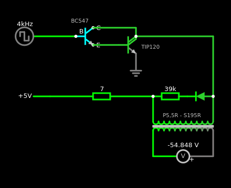
I drew that circuit on www.falstad.com (this link takes you to my actual circuit) and got several kV out of the simulation lol.
I used the original transformer: i could only measure resistance, so 5,5ohms on primary side, and 195ohms on secondary.
First transistor hooked to wave generator is J3Y. I replaced it with a BC547 (the "copy-paste" engineer hidden inside my head told me it's fairly close lol).
Second transistor is labeled J41CG and seems pretty strong to me so i replaced it with TIP120 .
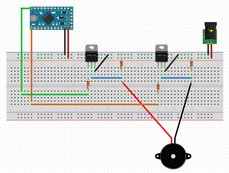
Next I put all these components onto the breadboard, and load my favourite Nano with this sketch :
const int buzzerPin = 9;
int i = 0;
unsigned long duration = 1000;

void setup() {
  pinMode(buzzerPin, OUTPUT);
}

void   loop() {
  for (i = 1000; i < 5000; i++) {
    tone(buzzerPin, i, duration);
  }
  for (i = 5000; i > 1000; i--) {
    tone(buzzerPin, i, duration);
  }
}
That is ever so LOUD !!
So this is plenty good enough for my little project !
-
There are also a lot of circuits using 555 timers and some old CMOS or TTL chips that easily create the oscilation you need. It draws a bit more power when the piezo is active. But for me that's worth it, because it gets rid of the complication in the code.
And is you have a bad MySensors radio connection, MySensors will keep executing code that might interrupt code. Which is annoying for applications like this, because it will interfere with your piezo sound. That's why I prefer a hardware solution or an active piezo buzzer. The ones that have a range from 3.3V to 24V are usually very load at 24V. They can be driven with a simple fet.At least that's how I look at electronics now, don't jump to a software solution when some old skool electronics make your life easier.
But I love the project!
-
Next step is to measure battery voltage on a daily basis.
Current setup is as follow:
- Pro Mini 8MHz 3.3V (regulator removed)
- Single cell LiPo (4.2V)
- Solar panel (unknown specs)
- Solar charger/boost to 5.0V based on 4056 chip
My reference for this part of the project is this post :
@Anticimex said in New library to read Arduino VCC supply level without resistors for battery powered sensor nodes that do not use a voltage regulator but connect directly to the batteries ;-)I would like to activate the voltage divider on demand, via a transistor (NDP6020P as per previous link) as to not draw voltage 24/7 on a permanent divider.
I am also considering using AVR's internal 1.1V reference to measure the voltage.
Simulation gives this: link to falstad
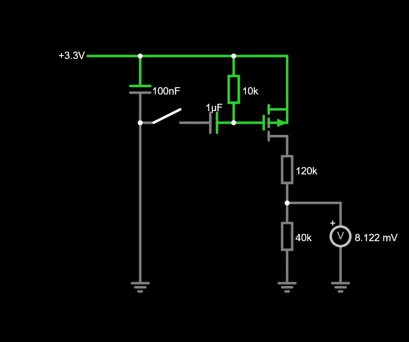
As one looks at the "live" simulation one can notice that the transistor leaks a bit... a few mV.. that's the bit that worries me.
Is this a flaw from the calculation or does a transistor leak anyway ?
Thanks a lot for your suggestions !
-
Just curious, still learning. Would a mosfet not draw less power? You could use a Mosfet and use a diode instead of a resistor to pull it high or low. That way it consumes micro amps.
-
Just curious, still learning. Would a mosfet not draw less power? You could use a Mosfet and use a diode instead of a resistor to pull it high or low. That way it consumes micro amps.
@TheoL thanks a lot for your suggestions
Unfortunately this is way above my league
And i'm not brainy enough to modify his designI am using that same transistor mentionned in @Anticimex 's post
My question was very general : does a transistor leak and by how much (is that a figure even given is the specs sheet?)
Thanks you anyway for replies
-
Can't give you a 100% answer. I've noticed with FETS I sometimes have a low leak Voltage. But I've seen Chinese designs that gave a negative voltage when the FET was turned off haha
Hello! It looks like you're interested in this conversation, but you don't have an account yet.
Getting fed up of having to scroll through the same posts each visit? When you register for an account, you'll always come back to exactly where you were before, and choose to be notified of new replies (either via email, or push notification). You'll also be able to save bookmarks and upvote posts to show your appreciation to other community members.
With your input, this post could be even better 💗
Register Login