Sensor shield for Arduino Pro Mini 3.3V with boost up regulator
-
Yeah, my concern with the MCP1640 is that the link I posted to eevblog is on to something and that it is misbehaving. They never seemed to hit their uA targets, though it may be user error.
My main motivation for other regulators though, like the TPS61221, is that you need two less components, and thus less board space. I think the TPS61221 is about twice as expensive as the MCP1640. And the LTC3525 is about twice as expensive as the TPS61221. Those are the only regulators I have on hand, but there have been MANY more discussed in various posts. For me it is convenient that both the TPS61221, LTC3525 (and MCP1640) are available on AliExpress so I can avoid expensive shipping costs and probable customs fees.
-
Hello,
I've been reading here for quite a while and now I want to share my idea of a project with you. I love all the wonderful projects that are shown here, but I wanted to have a shield, where I can put an Arduino pro mini (china clone) and NRF24L01+ into and have connections for sensors outside together with a boost up regulator so I can use 1 or 2 cells for powering.
Here is what I came up with. I really like to hear your ideas and suggestions, I tried to incorporate as many ideas and thoughts that I found elsewhere on this forum. It's actually the first time, that I'm trying to make my own pcb.Here's the scheme:
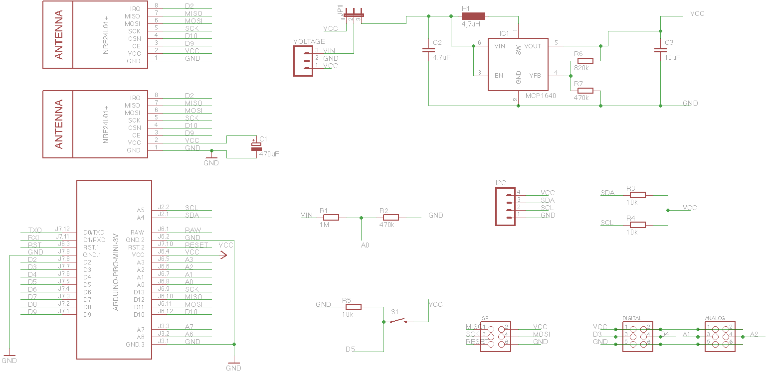
So these are the parts:
-
arduino pro mini 3.3V (china clone, have to remove voltage regulator and led)
-
two places to plug in the NRF24L01+ module (in both cases the antenna will not be covered by the shield pcb)
-
for voltage regulation, there is a MCP1640 (less power consumption than NCP1402 when everything is asleep)
-
a voltage divider on A0 to check battery voltage
-
a push button on D5
-
ISP port for programming
-
I2C port with pull-ups on SDA and SCL
-
two digital (D3 & D4) and two analog (A1 & A2) pins together with GND and VCC for sensors on 3-pin connectors
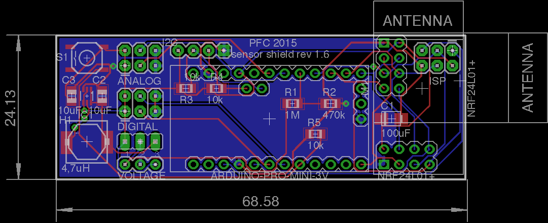
So my first pcb would look like this:
Size is 2.4 x 7.9 cm, it could be smaller but I need space for SMD soldering.
What do you think? Is the design worth sending to China for pcb manufacturing or do you have any ideas how to make it better?Thanks a lot,
Philipp@phil83
Why not put the pro mini circuitry on the board in the first place? -
-
@GaryStofer What do you mean by putting the mini circuitry on the board? You mean just use an Atmega328 instead of the Pro Mini board? The reason for this is that the Pro Mini nearly costs as much as the parts and my soldering skills are not good enough to solder the Atmega directly onto the board.
I had to create a new user name - I can't log into the old any more, the password reset feature is also not working - sorry. -
@hawk_2050 @bjornhallberg Thanks for the information about the TPS61221. I checked the data sheet and also checked availability at AliExpress. I guess I'm going to switch to that one.
-
Yeah, you're probably not saving a whole lot of money doing your own arduino-like board from scratch. Can't seem to find cheap ATMEGA328P-MU on AliExpress either, only ATMEGA328P-AU. But then to really save space you'd have to use the "mini" nrf24 module as well.
-
@bjornhallberg Yes, I totally agree... I could save probably 2cm in length of the board but have much more to solder.
-
Just curious - if Vin < VCC, why are you using a voltage divider to get the battery voltage? If you are using VCC as the ADC reference, you should be good without a divider, I'd think.
It would be possible to use the 1.1v internal reference (ONLY when measuring battery, not most sensors), in which case your divider could make sense, and that would remove the stability of the VCC power supply from the measurement - tho I rarely see that approach taken.
-
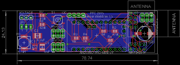
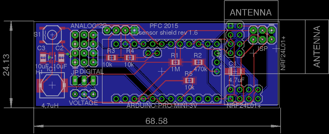
@maha Yes you're right, they are quite close... but they should be fine with my manufacturer. I'll try tonight to see what I can do to get the traces a little more apart, let's see. When I use the Gerber file, I can't find any spots where the lines are touching. The picture taken directly from Eagle is also probably not that accurate.
-
Another nitpick ... there are a lot of different Pro Mini pin layouts (http://arduino-board.com/boards/arduino-pro-mini). I don't know where you buy yours and if you can be sure of a certain pin layout, but I would probably not bet on anything other than the side rows that are present on all boards. A4 and A5 are fairly certain, but other than that ....
-
@bjornhallberg completely right - I have some here from Aliexpress and have a good and fast seller... but I asked for exactly that design before ordering...
-
@Zeph I wanted to use the internal reference as described here: http://www.mysensors.org/build/battery
What do you think?@phil83 said:
@Zeph I wanted to use the internal reference as described here: http://www.mysensors.org/build/battery
The voltage divider in that circuit diagram is for measuring an input voltage (into the regulator) higher than Vcc (out of the regulator). Bad idea without a voltage divider. Since you are instead using an up-converter and Vin < Vcc, I think you can do without the voltage divider resistors.
As an example, suppose you used one cell at 1.5v draining to 1.ov. With a Vcc of 3.3v a direct reading would give ADC readings of 465 falling to 310. Using that voltage divider would yield 149 falling to 99. (all out of 0 to 1023). You just lose resolution by inserting the divider. (WIth two cells double these numbers).
The caveat is that I'm uncertain about is startup transients - with Vin applied to the pin before Vcc stabilizes. Not sure if that's a real problem or not, tho - maybe somebody else would have thoughts.
-
@phil83 said:
@Zeph I wanted to use the internal reference as described here: http://www.mysensors.org/build/battery
The voltage divider in that circuit diagram is for measuring an input voltage (into the regulator) higher than Vcc (out of the regulator). Bad idea without a voltage divider. Since you are instead using an up-converter and Vin < Vcc, I think you can do without the voltage divider resistors.
As an example, suppose you used one cell at 1.5v draining to 1.ov. With a Vcc of 3.3v a direct reading would give ADC readings of 465 falling to 310. Using that voltage divider would yield 149 falling to 99. (all out of 0 to 1023). You just lose resolution by inserting the divider. (WIth two cells double these numbers).
The caveat is that I'm uncertain about is startup transients - with Vin applied to the pin before Vcc stabilizes. Not sure if that's a real problem or not, tho - maybe somebody else would have thoughts.
@Zeph
I think you're wrong. The divider works perfectly when measuring against internal reference like shown at the build-site. I think it's very well proven and I have never had any issues. And this is for battery voltage LOWER than Vcc.
I think I had a link to one of my code example here as well.
But sure, if you have a stable and known Vcc you could use that as reference instead. Without divider.@phil83
Why don't you use the recommended 0.1uF capacitor in parallel with R2 ?