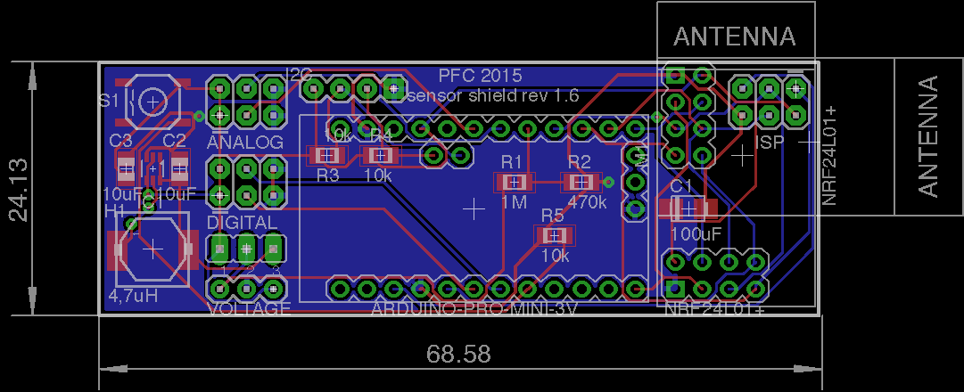
Sensor shield for Arduino Pro Mini 3.3V with boost up regulator
-
Just curious - if Vin < VCC, why are you using a voltage divider to get the battery voltage? If you are using VCC as the ADC reference, you should be good without a divider, I'd think.
It would be possible to use the 1.1v internal reference (ONLY when measuring battery, not most sensors), in which case your divider could make sense, and that would remove the stability of the VCC power supply from the measurement - tho I rarely see that approach taken.
-
@maha Yes you're right, they are quite close... but they should be fine with my manufacturer. I'll try tonight to see what I can do to get the traces a little more apart, let's see. When I use the Gerber file, I can't find any spots where the lines are touching. The picture taken directly from Eagle is also probably not that accurate.
-
Another nitpick ... there are a lot of different Pro Mini pin layouts (http://arduino-board.com/boards/arduino-pro-mini). I don't know where you buy yours and if you can be sure of a certain pin layout, but I would probably not bet on anything other than the side rows that are present on all boards. A4 and A5 are fairly certain, but other than that ....
-
@bjornhallberg completely right - I have some here from Aliexpress and have a good and fast seller... but I asked for exactly that design before ordering...
-
@Zeph I wanted to use the internal reference as described here: http://www.mysensors.org/build/battery
What do you think?@phil83 said:
@Zeph I wanted to use the internal reference as described here: http://www.mysensors.org/build/battery
The voltage divider in that circuit diagram is for measuring an input voltage (into the regulator) higher than Vcc (out of the regulator). Bad idea without a voltage divider. Since you are instead using an up-converter and Vin < Vcc, I think you can do without the voltage divider resistors.
As an example, suppose you used one cell at 1.5v draining to 1.ov. With a Vcc of 3.3v a direct reading would give ADC readings of 465 falling to 310. Using that voltage divider would yield 149 falling to 99. (all out of 0 to 1023). You just lose resolution by inserting the divider. (WIth two cells double these numbers).
The caveat is that I'm uncertain about is startup transients - with Vin applied to the pin before Vcc stabilizes. Not sure if that's a real problem or not, tho - maybe somebody else would have thoughts.
-
@phil83 said:
@Zeph I wanted to use the internal reference as described here: http://www.mysensors.org/build/battery
The voltage divider in that circuit diagram is for measuring an input voltage (into the regulator) higher than Vcc (out of the regulator). Bad idea without a voltage divider. Since you are instead using an up-converter and Vin < Vcc, I think you can do without the voltage divider resistors.
As an example, suppose you used one cell at 1.5v draining to 1.ov. With a Vcc of 3.3v a direct reading would give ADC readings of 465 falling to 310. Using that voltage divider would yield 149 falling to 99. (all out of 0 to 1023). You just lose resolution by inserting the divider. (WIth two cells double these numbers).
The caveat is that I'm uncertain about is startup transients - with Vin applied to the pin before Vcc stabilizes. Not sure if that's a real problem or not, tho - maybe somebody else would have thoughts.
@Zeph
I think you're wrong. The divider works perfectly when measuring against internal reference like shown at the build-site. I think it's very well proven and I have never had any issues. And this is for battery voltage LOWER than Vcc.
I think I had a link to one of my code example here as well.
But sure, if you have a stable and known Vcc you could use that as reference instead. Without divider.@phil83
Why don't you use the recommended 0.1uF capacitor in parallel with R2 ? -
Hey folks,
I just received my first boards today. They really look nice, I never believed that it is so easy! Especially the manufacture in china was pretty cheap and looks really good. I had to wait four weeks, nearly perfect!
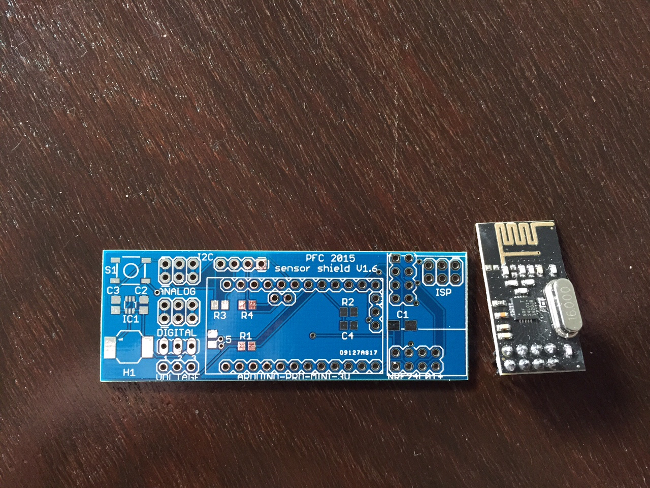
Now I'm waiting for two more capacitors, all the other parts were delivered already. I hope to be able to solder next week and will keep you updated afterwards!
I think I got infected by a virus by now since I'm already planning the next board ;-).Thanks again for all your help,
Philipp -
Hi everyone,
I received the last parts on monday and populated 2 boards so far. I found out, that one header for nrf24 is not working properly... most likely since the wires are too far away from the capacitor. The other header is working perfect. Here are the first pictures of the populated board:
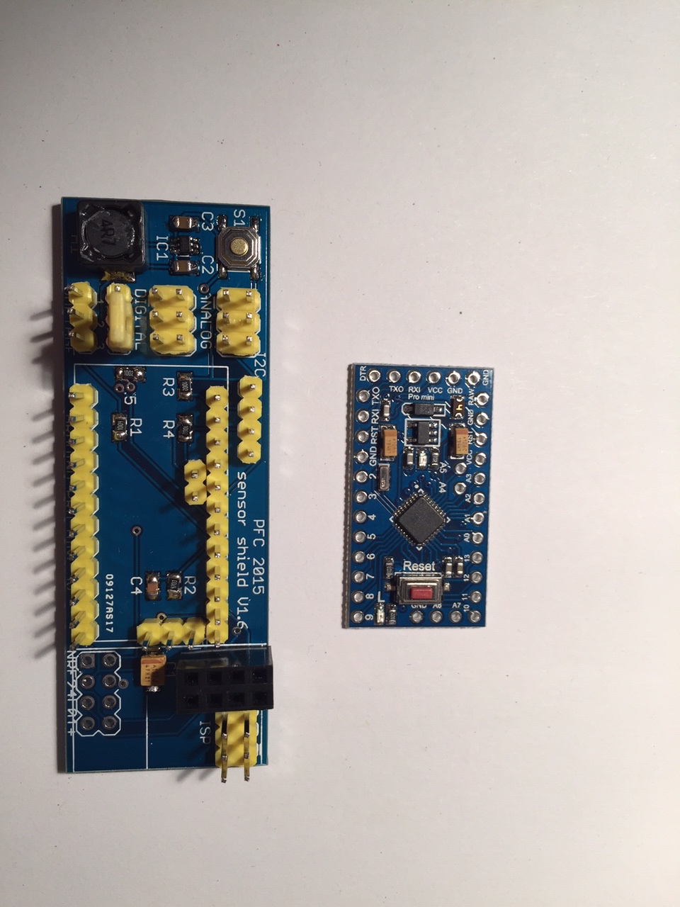
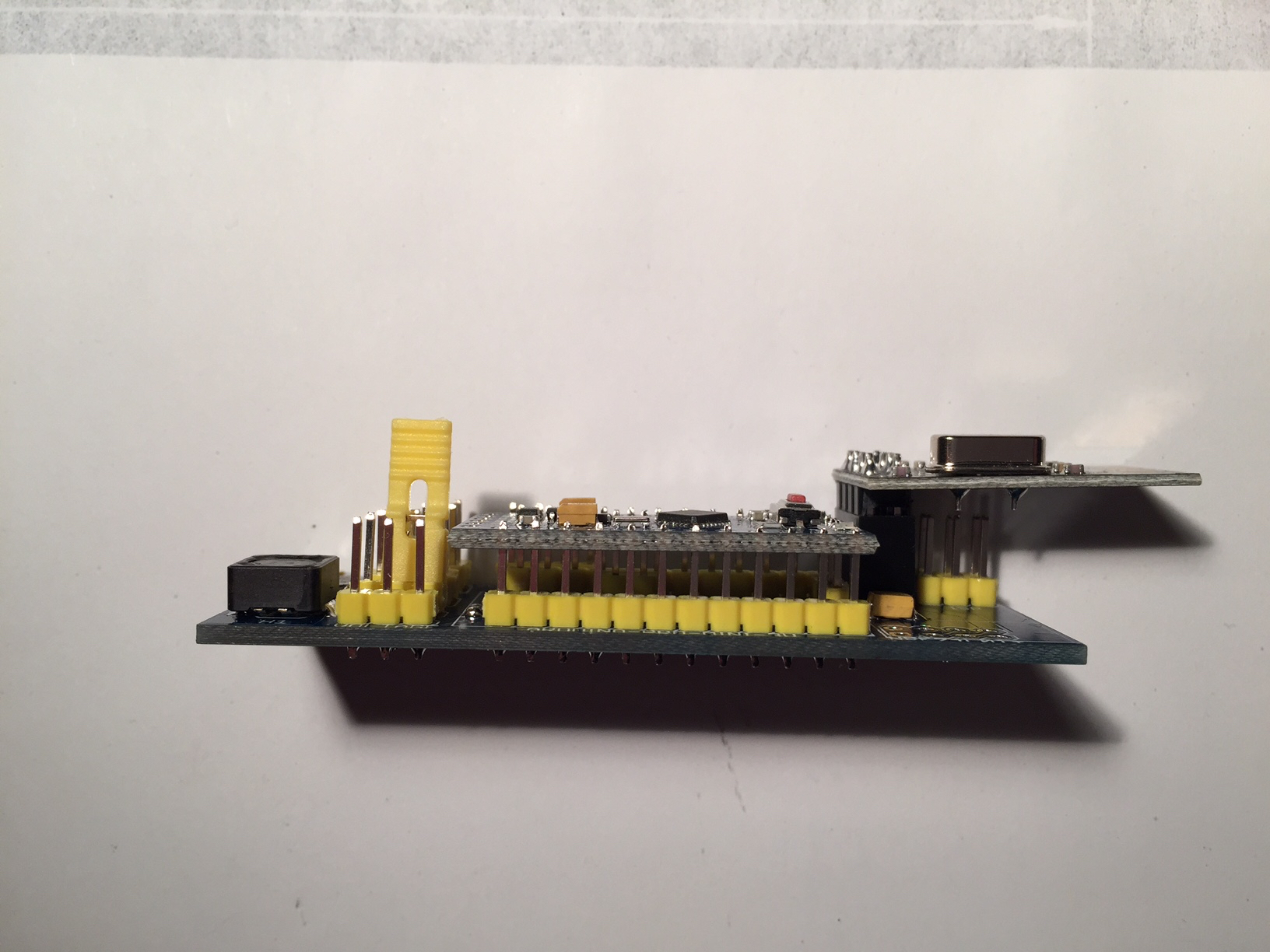
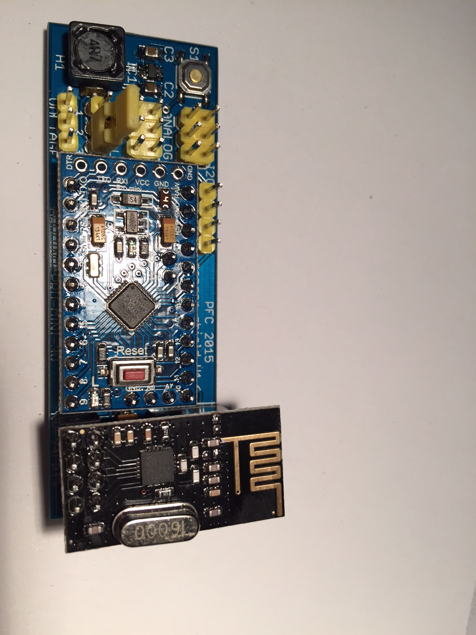
Though the hand soldering of the sot23-6 was not easy at all, I managed to do it. I tested the boards with the BatteryPoweredSensor and the voltage divider is working properly. I will now start to program more and see which sensor I can build with that board.
Thanks again for all your help,
Philipp