CAN bus transport implementation


  • @Adam-Slowik said in CAN bus transport implementation:

    20:30:09.340 -> 2097 !TSM:FPAR:NO REPLY

    This means the node doesn't get an answer from the gateway on the find parent request. If that occurs three times, the transport is reinitialised


  • Question: Is your gateway connected to some controller software?
    Afaik, MySensors won't work propperly without, this is what you experience as problems with ID request and transport layer reset. Though there are options to get around that, I'd strongly recommend to involve one.


  • a request for information, how to do :

    to add the CAN transport you have to modify the files or replace them with what exists ?

    I will maybe test the work of AdamSlowik


  • Hi @JeeLet, to test my implementation You should:

    1. Set up hardware as described in my first post in this thrread.
    2. Download source from my fork (https://github.com/AdamSlowik/MySensors/archive/refs/heads/development.zip)
    3. Somewhere in Your lib folder swap official MySensors files with those downloaded.
    4. Upload "CANSwitch.ino" to first arduino and "GatewaySerialCAN.ino" to second one. Both files can be found in examples.

    If everything is fine then You Should get results similar to those presented in my post dated to "14 Jul 2020, 20:42"

    Please let Us know if You managed to reproduce My results.


  • Hello
    thank you for the answer

    questions:

    I prepare another test computer for the installation of your version ๐Ÿ™‚

    Translated with www.DeepL.com/Translator (free version)


  • 1

    • which CAN library did you start on,

    I have used https://github.com/coryjfowler/MCP_CAN_lib
    This library is embedded in code in my fork, so if You are going to test My fork You don't have to worry about underlying library. Consider it an implementation detail. If You are going to implement CAN bus transport at Your own, You can pick different library.

    2

    • the management of Float values is also managed ?

    I did not tested transferring float numbers over CAN network, however in my opinion such concern is out of the scope of protocol implementation. During implementation My goal was to transfer array of bytes from one arduino to another via CAN. I don't care how those bytes are interpreted. Those bytes can be Strings, ints, floats, images etc. It should not matter.

    3

    Any CAN module supported by underlying library should be ok (so after all it's not an implemantation detail). Library readme says it will work with MCP2515 and MCP25625. Module picked by You (https://www.gotronic.fr/art-module-bus-can-sbc-can01-28405.htm) have MCP2515+MCP2562 so You should be god. Module used by Me had MCP2515+tja1050. Yours transciever is different then mine, however I hope it doesn't matter

    4

    I prepare another test computer for the installation of your version ๐Ÿ™‚

    I would really appreciate Your feedback


  • "you can choose a different library"
    I like this freedom of choice, my questioning is not necessary ๐Ÿ™‚

    "I would really appreciate your comments"
    yes yes in 4 to 5 days, theoretically

    Finally a high reliability Wired Bus for MySensors with the MyS protocol which is extraordinarily rich.
    (the RS485 bus is good, but the cables/wiring must be more rigorous and the management of collisions more delicate for X Nodes, and the CAN bus is a good field bus )


  • Hello

    to save time, you can tell me more about the configuration of MCP_CAN_lib

    not all settings are shown on the MyS sketch ๐Ÿ™‚

    here in an example https://github.com/coryjfowler/MCP_CAN_lib/blob/master/examples/CAN_receive/CAN_receive.ino
    there are some parameters to adjust

    or the filters https://github.com/coryjfowler/MCP_CAN_lib/blob/master/examples/Extended_MaskFilter/Extended_MaskFilter.ino

    can you indicate me the files in question ???
    (I think I have found but to confirm)

    to make it clean

    thanks


  • So I have pull up some config parameters. Those are defined and briefly described in:
    https://github.com/AdamSlowik/MySensors/blob/development/MyConfig.h
    lines 270-315
    You can set those parameters to different values, but for first run I suggest deploy examples without modifications. By examples I mean those 2 files:
    https://github.com/AdamSlowik/MySensors/blob/development/examples/CANSwitch/CANSwitch.ino
    https://github.com/AdamSlowik/MySensors/blob/development/examples/GatewaySerialCAN/GatewaySerialCAN.ino

    If it fails I would set:
    CAN_CLOCK to MCP_16MHZ
    because i think can module from Your vendor uses 16MHz (My used 8MHz)

    filters are set in:
    https://github.com/AdamSlowik/MySensors/blob/development/hal/transport/CAN/MyTransportCAN.cpp
    line 37 method _initFilters()
    without clear reason (eg. bug) I would recommend to not alter it.
    Filters are set to drop messages not intended for certain node. Thanks to this MCU do not have to handle 'spam'.

    If My answer answers Yours questions then great. If this is insufficient ask for a specific parameter or line in code I will try to answer any questions asap


  • a start of error messages return (on both sketches)
    IDE version 1.8.19

    for CANSwitch.ino

    the message returns me to the line
    MyTransportCAN.cpp --->
    163 : ",TOTAL=%"PRIu8",CURR=%"PRIu8",TO=%"PRIu8",FROM=%"PRIu8"\n"), header, messageId, totalPartCount,
    228 : ",TOTAL=%"PRIu32",CURR=%"PRIu32",TO=%"PRIu32",FROM=%"PRIu32"\n"), rxId, messageId,

    the one copy (a part) of the IDE

    In file included from /home/mci/Arduino/libraries/MySensors-development/MySensors.h:395:0,
                     from /tmp/arduino_modified_sketch_39381/CANSwitch.ino:43:
    /home/Arduino/libraries/MySensors-development/hal/transport/CAN/MyTransportCAN.cpp:163:17: warning: invalid suffix on literal; C++11 requires a space between literal and string macro [-Wliteral-suffix]
                     ",TOTAL=%"PRIu8",CURR=%"PRIu8",TO=%"PRIu8",FROM=%"PRIu8"\n"), header, messageId, totalPartCount,
                     ^
    /home/Arduino/libraries/MySensors-development/hal/transport/CAN/MyTransportCAN.cpp:163:32: war......
                                                              ^...
    /home/Arduino/libraries/MySensors-development/hal/transport/CAN/MyTransportCAN.cpp:228:18: warning: invalid suffix on literal; C++11 requires a space between literal and string macro [-Wliteral-suffix]
                      ",TOTAL=%"PRIu32",CURR=%"PRIu32",TO=%"PRIu32",FROM=%"PRIu32"\n"), rxId, messageId,
                      ^
    /home/Arduino/libraries/MySensors-development/hal/transport/CAN/MyTransportCAN.cpp:228:34: warni.....


  • https://sourcecodeartisan.com/2021/03/06/invalid-suffix-on-literal.html

    for the Error code it is
    a requirement in C++ 11 (or later).

    lines 163 and 228 modify and error resolved

    .../hal.transport/CAN/MyTransportCAN.cpp

    CAN_DEBUG(PSTR("CAN:SND:CANH=%" PRIu32 ",ID=%" PRIu8 ",TOTAL=%" PRIu8 ",CURR=%" PRIu8 ",TO=%" PRIu8 ",FROM=%" PRIu8 "\n"), header, messageId, totalPartCount,
    
    CAN_DEBUG(PSTR("CAN:RCV:CANH=%" PRIu32 ",ID=%" PRIu32 ",TOTAL=%" PRIu32 ",CURR=%" PRIu32 ",TO=%" PRIu32 ",FROM=%" PRIu32 "\n"), rxId, messageId,
    

    ๐Ÿ‘


  • a topo of the day

    on the hardware side, I got screwed with an arduino pin that became too soft, too dilated, look for an hour before understanding why no dialog.

    Otherwise, on the Gateway side, no problem, MyController recognized well.

    and CAN_Switch.ino is good too, my Widget on MyC switches well on the switch change.

    listing of the dialog pour le Node 51 (set up in a fixed place )

    coter log from MyC:

    2022-06-11T18:49:35.167+0200	recd	0;255;3;0;9;1482640 TSF:MSG:READ,51-51-0,s=4,c=1,t=16,pt=1,l=1,sg=0:1
    2022-06-11T18:49:35.170+0200	recd	51;4;1;0;16;1
    2022-06-11T18:49:35.179+0200	recd	0;255;3;0;9;1482653 TSF:MSG:READ,51-51-0,s=255,c=3,t=21,pt=1,l=1,sg=0:0
    2022-06-11T18:49:35.182+0200	recd	51;255;3;0;21;0
    

    coter IDE from MyS:

    67889 TSF:MSG:BC
    68197 TSF:MSG:SEND,51-51-0-0,s=255,c=3,t=21,pt=1,l=1,sg=0,ft=0,st=OK:0
    68203 TSF:MSG:READ,0-0-255,s=255,c=3,t=20,pt=0,l=0,sg=0:
    
    68208 TSF:MSG:BC
    68836 TSF:MSG:SEND,51-51-0-0,s=255,c=3,t=21,pt=1,l=1,sg=0,ft=0,st=OK:0
    
    68843 MCO:SLP:MS=5,SMS=0,I1=255,M1=255,I2=255,M2=255
    68848 TSF:TDI:TSL
    68849 MCO:SLP:WUP=-1 ........ it is incomplete 
    

    well now we have to calm down the CAN bus dialog, the Rx/Tx Led of the gateway looks like a Christmas tree ๐Ÿ™‚

    tomorrow I'll test a CAN_Switch version2 sketch


  • test with the digital output inputs of 2 Arduino on CAN Bus.

    • status of a button and control of a led with MyC

    a proof in video that it is functional ๐Ÿ™‚

    video

    all is not functional, on the end of the video, the reset or reboot does not work, (but functional with the RS485 bus)
    .... to follow ๐Ÿ˜‰
    (now the Analog values, decimal to test )

    I would like to test the Node to Node with the filtering.
    a question : is it difficult to put the filters on the MySensors sketch ???

    there are still MySensors on the forum ???
    if yes, a help for Adam Slowik would be a great thing.
    implement it in MyS Yes Yes

    Thanks


  • @JeeLet as I can see You had bussy weekend. I was AFK so I was unable to respond. Within working days I should be able to respond quicker.

    @JeeLet said in CAN bus transport implementation:

    lines 163 and 228 modify and error resolved

    Can you push Your fix to My repo?

    @JeeLet said in CAN bus transport implementation:

    a proof in video that it is functional

    Great job! I never was at this stage.

    @JeeLet said in CAN bus transport implementation:

    all is not functional, on the end of the video, the reset or reboot does not work, (but functional with the RS485 bus)
    .... to follow

    Can You provide (gateway/node) logs from reset scenario. It would be great to have those logs either for RS485 and CAN so I can compare them.

    @JeeLet said in CAN bus transport implementation:

    I would like to test the Node to Node with the filtering.
    a question : is it difficult to put the filters on the MySensors sketch ???

    Could You describe what kind of test You would like to perform? Right now there is no way to set filters from the sketch. I think it should stay this way.

    Perhaps We have different things in mind when We think about filters. I'll try to describe how I see this.

    When it comes to CAN frame there is header and body. Header contains metadata and body contains data. mcp2515 can filter frames based on header content. Header contains id of destination node. Based on this id filters are set to drop any messages not intended for current node. This way if gateway want to send message to node with id=51 only node with this id receives this message.

    There is exception for this rule. Messages with destination id set to BROADCAST_ADDRESS reaches all nodes.

    With this in mind I see no reason to set filters differently. Of course I can be wrong.

    Composition of header is described in MyTransportCAN.cpp in method _buildHeader()

    As of now my all can modules and arduinos are burried in some box at My attic so I am unable to test anything


  • "Can you provide logs (gateway/node) from the reset scenario. It would be great to have these logs for RS485 and CAN so I can compare them."

    listing

    Released today 2 gateways connect to MyController

    • UNO_usb - Gateway and RS485 bus
    • UNO_usb - Gateway and CAN Bus

    with connect, a UNO with the basic sketch "RelayWithButtonActuator_base.ino" (slightly modified)
    with ... a Led and a Switch, for each bus.

    The Listing split in several parts

    "Log of the IDE and MyC for the two types of bus (node34 and node 54), CAN and RS485.

    - Listing Action RESET with MyController 
    	2 parts for CAN
    	and 
    	2 parts for RS485
    	
    
    and 
    
    - Listing Action On/Off on the node switch or with MyController 
    	4 parts for CAN
    	and 
    	4 parts for RS485
    

    No error on the Reset, it works fine, an error from me.

    Oh yes, I even found an error ๐Ÿ™‚
    the sendSketchInfo("test xxxxx", "1.0"); is not up

    see the end of the video
    video

    ....I will answer the other question tomorrow.


  • @Adam-Slowik "Can you push your patch to my repository? " .... I don't know how

    On the CAN principle

    @Adam-Slowik "Based on this id, the filters are configured to remove all messages not intended for the current node. This way, if the gateway wants to send a message to the node with id = 51, only the node with that id receives that message." ... yes, that's how I see it.

    another way to say/explain it.

    "The philosophy of CAN is to constitute a messaging system.
    The messages (the letter) send on the CAN Bus (the post office), distributed by the CAN Bus (the letter carrier).

    Each (letter) have each an identifier (stamp of the post โ˜บ ) that ... identifies it.
    And put in the right mailbox (the MCP2515) according to the choice of filter/mask ( color, scent? โ˜บ ) of the letter."

    So there are two "stratum" of dialogue / work.

    • one on the Can Bus, and another on the Nodes.

    The idea is to relieve the Nodes of unnecessary work/effort with the risks that this brings. Less letter to open ๐Ÿ™‚

    @Adam-Slowik "... my modules and arduinos are buried in a box in my attic..." ? Arduino 8bit and MySensors is over for you?
    ( if it's a personal / family reason don't say anything )


  • I tested my sketch with clock and OLED to see ๐Ÿ™‚

    bah No the time is not up ๐Ÿ˜ž

    I give this information for an overview, it can help for the continuation (but not to give you work ๐Ÿ™‚ )

    The listing of the messages of mySensors

    test with "void receiveTime" function (without RTC clock)
    https://forum.mysensors.org/topic/4809/real-time-clock-module-lcd-display-and-controller-time/8?_=1655208396048

    ..........Log MyC - terminal ssh  .........
    2022-06-14T14:01:45.115+0200	recd	0;255;3;0;9;65310350 TSF:MSG:READ,55-55-0,s=255,c=3,t=1,pt=0,l=0,sg=0:
    2022-06-14T14:01:45.119+0200	recd	0;255;3;0;9;65310356 TSF:MSG:ECHO REQ
    2022-06-14T14:01:45.127+0200	recd	0;255;3;0;9;65310360 TSF:MSG:SEND,0-0-55-55,s=255,c=3,t=1,pt=0,l=0,sg=0,ft=0,st=OK:
    2022-06-14T14:01:45.127+0200	recd	55;255;3;0;1;
    2022-06-14T14:01:45.146+0200	sent	55;255;3;0;1;1655215305
    2022-06-14T14:01:45.160+0200	recd	0;255;3;0;9;65310394 TSF:MSG:SEND,0-0-55-55,s=255,c=3,t=1,pt=0,l=10,sg=0,ft=0,st=OK:1655215305
    
    
    ..........Log MyS - terminal IDE .........
         time current:0   -------------------------------------------  
    58007 TSF:MSG:SEND,55-55-0-0,s=255,c=3,t=1,pt=0,l=0,sg=0,ft=0,st=OK:
    58017 TSF:MSG:READ,0-0-55,s=255,c=3,t=1,pt=0,l=0,sg=0:
    58022 TSF:MSG:ECHO
    

    avec Bus RS485

    
    ..........Log MyC - terminal ssh  .........
    2022-06-14T14:22:41.265+0200	recd	0;255;3;0;9;72000090 TSF:SAN:OK
    2022-06-14T14:22:41.274+0200	recd	0;255;3;0;9;72000096 TSM:READY:NWD REQ
    2022-06-14T14:22:41.298+0200	recd	0;255;3;0;9;72000115 ?TSF:MSG:SEND,0-0-255-255,s=255,c=3,t=20,pt=0,l=0,sg=0,ft=0,st=OK:
    2022-06-14T14:22:41.917+0200	recd	0;255;3;0;9;72000736 TSF:MSG:READ,22-22-0,s=255,c=3,t=21,pt=1,l=1,sg=0:0
    2022-06-14T14:22:41.920+0200	recd	22;255;3;0;21;0
    
    
    .........Log MyS - terminal IDE .........
       time current:1422   -------------------------------------------  
    423956 TSF:MSG:READ,0-0-255,s=255,c=3,t=20,pt=1,l=1,sg=0:0
    423962 TSF:MSG:BC
    424008 TSF:MSG:SEND,22-22-0-0,s=255,c=3,t=21,pt=1,l=1,sg=0,ft=0,st=OK:0
       requestOn----------------------------------------- 


  • @JeeLet said in CAN bus transport implementation:

    Arduino 8bit and MySensors is over for you?

    No it is not over. Right now I don't have enough time. Now I am able to work for let's say 1 hour per week. Probably I will become more active at the end of 2023 ๐Ÿ˜„

    @JeeLet said in CAN bus transport implementation:

    bah No the time is not up

    Here You posted RS485 version:
    https://forum.mysensors.org/topic/4809/real-time-clock-module-lcd-display-and-controller-time/8?_=1655208396048

    Could You post here CAN version?


  • @Adam-Slowik "Could you post the CAN version here?"

    it's the same, except that the bus is not rs485 but CAN ๐Ÿ™‚

    ......
    ........
    #define MY_NODE_ID 55          /*Node en ID static*/
    
      #define MY_CAN
      
      #include "SSD1306Ascii.h"
    ........
    .....
    

    but I'll go back to PaulStoffregen's Lib <TimeLib.h> to see if I can simplify the basic sketch of MySensors


  • In previous example (with diodes) did You set CAN_CLOCK to MCP_16MHZ?


  • no it stayed on 8Mhz ?

    I didn't modify anything (the other sketches work)

    But I just looked at the quartz and it's 16M!! (SW-65-16M)

    I am lost ๐Ÿ˜ž

    https://www.gotronic.fr/art-module-bus-can-sbc-can01-28405.htm

    but on the doc there is :
    The 8000000 stands that the MCP2515 operates with a clock of 8 MHz. This
    depends on the quartz used and may need to be adjusted.

    error
    on the official doc it's a 16Mhz like mine.

    so 8Mhz or 16Mhz?
    and why does it work with the previous sketches?


  • I think the dialogue is good
    but the problem is the length of the storyline

    a part of the dialog on the IDE terminal for both types
    CAN and RS485

       - IDE terminal sur RS485 :
    
    4066 TSF:MSG:ECHO
    4132 TSF:MSG:READ,0-0-22,s=255,c=3,t=1,pt=0,l=10,sg=0:1655285320
    8018 TSF:MSG:SEND,22-22-0-0,s=255,c=3,t=1,pt=0,l=0,sg=0,ft=0,st=OK:
    8054 TSF:MSG:READ,0-0-22,s=255,c=3,t=1,pt=0,l=0,sg=0:
    8058 TSF:MSG:ECHO
    8111 TSF:MSG:READ,0-0-22,s=255,c=3,t=1,pt=0,l=10,sg=0:1655285324
      newTime:1655285324   -------------------------------------------  
    
    
      - IDE terminal sur CAN :
    
    22224 MCO:REG:REQ
    22226 TSF:MSG:SEND,55-55-0-0,s=255,c=3,t=26,pt=1,l=1,sg=0,ft=0,st=OK:2
    22233 !MCO:PRO:RC=1
    22235 TSF:MSG:READ,0-0-55,s=255,c=3,t=27,pt=1,l=1,sg=0:1
    22240 MCO:PIM:NODE REG=1
    28004 TSF:MSG:SEND,55-55-0-0,s=255,c=3,t=1,pt=0,l=0,sg=0,ft=0,st=OK:
    28014 TSF:MSG:READ,0-0-55,s=255,c=3,t=1,pt=0,l=0,sg=0:
    28019 TSF:MSG:ECHO
      newTime:0   -------------------------------------------  
    

    sketch

    void receiveTime(unsigned long controllerTime)   {   
        if (receiveTime) stateCom = true ; else stateCom = false;
          newTime = controllerTime;
    " " ....
    Serial.print("  newTime:"); Serial.print(newTime);


  • frequency change

    with 16Mhz I have a NACK

    // #define CAN_CLOCK MCP_16MHZ
    105 TSM:FPAR
    18107 ?TSF:MSG:SEND,55-55-255-255,s=255,c=3,t=7,pt=0,l=0,sg=0,ft=4,st=NACK:
      newTime:0   -------------------------------------------  
         time current:0   -------------------------------------------  
    20115 !TSM:FPAR:NO REPLY
    20117 TSM:FPAR
    20119 ?TSF:MSG:SEND,55-55-255-255,s=255,c=3,t=7,pt=0,l=0,sg=0,ft=5,st=NACK:
    
    // #define CAN_CLOCK MCP_8MHZ
    8004 TSF:MSG:SEND,55-55-0-0,s=255,c=3,t=1,pt=0,l=0,sg=0,ft=0,st=OK:
    28014 TSF:MSG:READ,0-0-55,s=255,c=3,t=1,pt=0,l=0,sg=0:
    28019 TSF:MSG:ECHO
      newTime:0   -------------------------------------------  
         time current:0   -------------------------------------------  
    38005 TSF:MSG:SEND,55-55-0-0,s=255,c=3,t=1,pt=0,l=0,sg=0,ft=0,st=OK:
    38016 TSF:MSG:READ,0-0-55,s=255,c=3,t=1,pt=0,l=0,sg=0:
    

    https://forum.arduino.cc/t/how-to-set-the-mhz-in-mcp2515-library-file-based-on-crystal-oscillator/628822


  • in the sketch I added lines to visualize the buffer data

    a part of I recopied

    log IDE :

    newTime:0   -------------------------------------------  
       Extended ID: 0x0410FF00  DLC: 8  Data: 0x00 0x00 0xFF 0x0A 0x23 0x14 0xFF 0x00
    88010 TSF:MSG:SEND,55-55-0-0,s=255,c=3,t=1,pt=0,l=0,sg=0,ft=0,st=OK:
    Extended ID: 0x05103700  DLC: 7  Data: 0x00 0x00 0x37 0x02 0x13 0x01 0xFF
    Extended ID: 0x06303700  DLC: 8  Data: 0x00 0x00 0x37 0x52 0x03 0x01 0xFF 0x31
      newTime:0   ------------------------------------------- 
    

    I stop for me, I pause for 1 day or 2 ๐Ÿ™‚


  • I found a bug in my code. Please re-download new version.

    If something won't work please enable CAN debug by adding:
    #define MY_DEBUG_VERBOSE_CAN

    add this to gateway and to node sketch


  • #define MY_DEBUG_VERBOSE_CAN .....yes yes I already tested it, it's very good.
    (a very useful function)

    ..go to

    • Reloading the CAN-MyS update
    • ClearEeprom of the GW and Nodes
    • Reloading of Sketches on GW and Nodes

    Bravo ๐Ÿ‹๏ธโ€โ™€๏ธ

    • sendSketchInfo(" text ...."); and well up

    • requestTime(receiveTime); and functional

    Ahhhhhh Lovely this is great ๐ŸŒˆ
    I offer the coffee crossing ๐Ÿฅ โ˜•

    (what was the problem ??? )

    After the test on the Digital I/O of the Nodes ,
    now I test the Analog I/O

    a Super Thank You @Adam-Slowik
    ๐Ÿ‘


  • a test with DHT22 probes.

    the values go up well on MyC
    real decimal values ๐Ÿ™‚

    here is a screen shot

    big vue

    I have to find another type of probes, the DHT22 give me losses, or my sketch is to review

    ReEdit
    error ๐Ÿ˜ 
    I got excited too fast
    the values are not refreshed.
    I look better ๐Ÿ‘“

    ReRe-edition
    I made a mistake, as I play a little too much with MyController, I add and remove gateways from nodes and other salads.
    and well in the end it makes no sense ๐Ÿ˜‰

    I cleaned up the Yaml files of MyC and it's better ๐Ÿ™‚


  • @JeeLet said in CAN bus transport implementation:

    what was the problem ???

    Previous messages used 7 bytes long payload. Single CAN frame is able to transfer 8 bytes. So all messages was contained in single frame. Example with time, used 17 (!) bytes long payload. In order to transfer 17 bytes there is need to split data to 3 messages (8+8+1). Next in the other side of wire You have to concat it. This mechanism of splitting and concating had a bug. For details check last 3 commits (at the bottom)
    https://github.com/mysensors/MySensors/compare/development...AdamSlowik:development


  • Gateway Logs on MyController
    (CAN Bus and RS485 Bus)

    two separate files
    CAN log
    RS485 log

    files split in parts :
    A : gateways startup
    B : reboot of the gateways
    C : launch of MyClock Nodes (id23 and id55)
    D ; periodic refresh requestTime(receiveTime)
    E ; send value (1700 and 2100)

    (I have prepared the work for you to read)

    a 1st analysis

    • (at the bottom of the listing, the sending of values "1700 or 2100" with MyC)
      The RS485 bus dialogues much more, the CAN bus is more timid ๐Ÿ™‚

    Adam Slowik bravo

    I test what now???
    the ACK ??

    Oh yes, I have to check the disconnection of the nodes.
    The Gateway gives me the impression that the information does not go back to MyC if a Node is off ???


  • @JeeLet said in CAN bus transport implementation:

    I test what now???

    I was at similar position some time ago:

    @Adam-Slowik said in CAN bus transport implementation:

    Any suggestion what to test next?

    I have no idea what to test next. I do not use MySensors. I hope this will change in the future, but as of now I'm a newbie.

    If You won't get any advice from more experienced users I would suggest to do some long running test to see if it's stable. If it's stable try to use it in some real use cases.

    If You find any bugs in transmission layer post logs here. I will do My best to support CAN, because I will need it in a future.


  • " I would suggest doing a long term test to see if it is stable." yes I will stress it to see the weakness

    ".. If it is stable, try to use it in real use cases." yes that's the point

    One last question

    I'm going from 8Mhz to 16Mhz (in development/MyConfig.h on line 306)

    question: can you explain how I can bring up in the sketch the parameters that are related to the MCP_CAN_lib library

    it should not be complicated for me ๐Ÿ™‚ it is only text to insert ???

    an example with the #define CAN_CLOCK MCP_8MHZ

    Thanks Adam Slowik


  • @JeeLet said in CAN bus transport implementation:

    I'm going from 8Mhz to 16Mhz (in development/MyConfig.h on line 306)

    In My opinion You should not override MyConfig.h. If You want to go for 16MHz You should put:

    #define CAN_CLOCK MCP_16MHZ
    

    in Your sketch. Preferably somewhere around line:

    #define MY_CAN
    

    @JeeLet said in CAN bus transport implementation:

    can you explain how I can bring up in the sketch the parameters that are related to the MCP_CAN_lib library

    If it's a parameter that is listed in MyConfig.h simply define it like 'CAN_CLOCK'. If parameter is not listed in MyConfig please let me know exactly what parameter You would like to modify, then I will try to figure it out.


  • I just did the test, switch to 16Mhz in the file MyConfig.h

    it works well, I have no error

    #define CAN_CLOCK MCP_16MHZ
    

    I didn't think it was possible, is it incompatible?
    overwritten the values of the file MyConfig.h

    thank you for the information


  • I'm not sure if We understood each other. This line #define CAN_CLOCK MCP_16MHZ should be in Your sketch. You should not modify MyConfig.h.
    Libraries (in general not only MySensors) should not be modified. MyConfig.h is part of library.

    Let's take a look at this code from MyConfig.h

    #ifndef CAN_CLOCK
    #define CAN_CLOCK MCP_8MHZ
    #endif. 
    

    This is if statement. If user didn't defined CAN_CLOCK define it as CAN_CLOCK MCP_8MHZ
    If user defined (in sketch) CAN_CLOCK then do nothing.

    So You can treat MyConfig.h as a set of defaults which can be overridden from sketch.

    I have put all relevant (in My opinion) properties from MCP_CAN_lib into MyConfig.h, so You can override them. If I have missed some relevant property please let Me know.


  • Thank you for this clarification.
    (yes translator and my neuron it gives crooked dialog)

    "If I have missed a relevant property, please let me know."

    The list of #define go up for the MySensors sketch .
    ( if I'm not mistaken ?)

    ***for MCP_CAN_lib **************** MyConfig.h line 280 to 315
    CAN_INT // Pin for interrupting an incoming message.
    CAN_CS // Chip selection pin.
    CAN_SPEED // Transmission speed. The allowed values can be found in mcp_can_dfs.h
    CAN_CLOCK // Can clock. Allowed values can be found in mcp_can_dfs.h.
    CAN_BUF_SIZE // Assembly buffer size. As long messages can be split and arrive mixed with other messages, an assembly buffer is needed.
    
    **** for MyS **************** MyConfig.h line 2492 to 2494
      MY_CAN // Set this to use the CAN wire transport for sensor network communication.
    MY_DEBUG_VERBOSE_CAN // Set this for verbose debugging printouts related to the %CAN driver.
    

    can be added, for testing and controlling the CAN bus

    #define CAN_MSGAVAIL    
    #define CAN_OK  
    #define CAN_CTRLERROR  
    

    Thanks

    return of the last 24 hours .
    CAN bus no error, good dialogue, no hole in the measurements and commands.

    the hardware base on the bus is :
    gateway + node 55 + node 56 .

    I will add another node 57.
    I think to go until 6 nodes


  • @JeeLet said in CAN bus transport implementation:

    The list of #define go up for the MySensors sketch .
    ( if I'm not mistaken ?)

    You are right.

    @JeeLet said in CAN bus transport implementation:

    can be added, for testing and controlling the CAN bus
    #define CAN_MSGAVAIL
    #define CAN_OK
    #define CAN_CTRLERROR

    I'm afraid i do not understand what You want to achieve.
    To clarify things lets look at CAN_CLOCK

    CAN_CLOCK can take values: 0 or 1 or 2 those values are defined in mcp_can_dfs.h:

    #define MCP_20MHZ    0
    #define MCP_16MHZ    1
    #define MCP_8MHZ     2
    

    If You want to use 8MHz You can
    #define CAN_CLOCK 2
    or
    #define CAN_CLOCK MCP_8MHZ
    Both lines will do the same. However #define CAN_CLOCK MCP_8MHZ is recommended approach.
    So CAN_CLOCK can take one of values values (0,1,2), and user (based on used hardware) should pick one of them.

    Next example could be CAN_INT. User should be able to pick which interrupt pin should be used.

    Now when it comes to:

    #define CAN_MSGAVAIL    
    #define CAN_OK  
    #define CAN_CTRLERROR  
    

    in mcp_can_dfs.h We can find a section:

    #define CAN_OK             (0)
    #define CAN_FAILINIT       (1)
    #define CAN_FAILTX         (2)
    #define CAN_MSGAVAIL       (3)
    #define CAN_NOMSG          (4)
    #define CAN_CTRLERROR      (5)
    #define CAN_GETTXBFTIMEOUT (6)
    #define CAN_SENDMSGTIMEOUT (7)
    #define CAN_FAIL       (0xff)
    

    This We can treat as return code dictionary.
    For example when I initialize CAN in MyTransportCAN.cpp:

    	if (CAN0.begin(MCP_STDEXT, CAN_SPEED, CAN_CLOCK) != CAN_OK) {
    		canInitialized = false;
    		return false;
    	}
    	canInitialized = true;
    

    I could write if (CAN0.begin(MCP_STDEXT, CAN_SPEED, CAN_CLOCK) != 0 but recommended approach is to use dictionary key (CAN_OK) instead of dictionary value (0)

    Now overriding CAN_OK to 777 instead of 0 is possible, but it won't cause nothing but chaos. If We do that the function CAN0.begin(MCP_STDEXT, CAN_SPEED, CAN_CLOCK) would return 777 instead of 0. I don't think user should do that.

    Code from mcp_can.cpp:

    INT8U MCP_CAN::checkReceive(void)
    {
    	INT8U res;
    	res = mcp2515_readStatus();                                         /* RXnIF in Bit 1 and 0         */
    	if (res & MCP_STAT_RXIF_MASK) {
    		return CAN_MSGAVAIL;
    	} else {
    		return CAN_NOMSG;
    	}
    }
    

    This function returns dictionary key CAN_MSGAVAIL or CAN_NOMSG but if We could stop in debug We would see 3 or 4
    Again overriding CAN_MSGAVAIL to let's say 42 won't give user nothing.

    @JeeLet said in CAN bus transport implementation:

    return of the last 24 hours .
    CAN bus no error, good dialogue, no hole in the measurements and commands.
    the hardware base on the bus is :
    gateway + node 55 + node 56 .
    I will add another node 57.
    I think to go until 6 nodes

    I keep My fingers crossed. Great job.


  • The original idea was: how to check the status of the CAN bus.

    . is there any dialogue ?
    . are there any messages?

    of course this can be done with MySensors.

    But to get as close as possible to the communication channel (the CAN bus) I thought it was easy to do.

    this is by reading the post of bricoleau here
    text french
    that the idea came to me.

    • on the arduino have a blinking led to say that the CAN bus is out of order (but we forget, it loads the program unnecessarily)

    and also because you suggested it to me
    yes we have to beat the iron when it is hot, and my time available for the computer will soon be reduced (purchase and work of a house)

    I appreciate very much your explanatory note, thank you

    I activated the 16Mhz in the sketch, and put it back in the library

      #define MY_NODE_ID 57          /*Node en ID static*/
    
      #define MY_CAN
      #define CAN_CLOCK MCP_16MHZ


  • @JeeLet said in CAN bus transport implementation:

    The original idea was: how to check the status of the CAN bus.
    . is there any dialogue ?
    . are there any messages?
    of course this can be done with MySensors.
    But to get as close as possible to the communication channel (the CAN bus) I thought it was easy to do.

    That is something I can work with. I will check if used library provides some function to check bus status.

    @JeeLet said in CAN bus transport implementation:

    my time available for the computer will soon be reduced (purchase and work of a house)

    I totally understand.


  • So library gives us 3 interesting functions:

    INT8U checkError(void);           
    INT8U errorCountRX(void);                                           
    INT8U errorCountTX(void);   
    

    Full description can be found in library source code and in documentation chapter 6:
    https://ww1.microchip.com/downloads/en/DeviceDoc/MCP2515-Stand-Alone-CAN-Controller-with-SPI-20001801J.pdf

    long story short:

    1. INT8U checkError(void); returns:
      -CAN_CTRLERROR when things are bad or very bad
      -CAN_OK when things are ok or not so bad (error counters below 96)
      I would like to chage implementation of sanity check to something like this:
    bool transportSanityCheck(void)
    {
    	return (CAN0.getError()==CAN_OK)
    }
    

    It won't blink diodes in case of communication problems, but will provide some feedback about communication to MySensors library.

    2)INT8U errorCountRX(void); return error counter for received messages. AFAIK this counter is incremented when error occurs and decremented when message is received. I'm not a 'radio guy' but i think this could be returned as int16_t transportGetReceivingSNR(void) or int16_t transportGetReceivingRSSI(void). I know SNR and RSSI are radio related parameters, but perhaps We could bend the border here. Maybe some 'radio guy' could say something about this idea?

    3)INT8U errorCountTX(void); same situation as with #2. 'Radio guy' opinion would by great.

    Again ideas #2 and #3 are not solving problems, but providing feedback to MySensors.

    Are My ideas ok, or do they do not pass sanityCheck() ๐Ÿ™‚


  • "Are my ideas good" .. yes yes c'est tout bon

    "It will not flash the diodes in case of communication problems" ... it's not a problem, Christmas is still far ๐Ÿ™‚

    But yes a counter that increments is a good thing.

    what do you want me to test ????

    bool transportSanityCheck(void)
    {
    	return (CAN0.getError()==CAN_OK)
    }
    

    The "radio guy" opinion would be great.
    ((I'll look for possible help ). )

    Re-Edit

    hal/transport/CAN/MyTransportCAN.cpp

    bool transportSanityCheck(void)
    {
    	// not implemented yet
    	return true;
    }
    

    ๐Ÿ˜œ

    Edit
    I searched the web, and using SNR RSSI with the CAN bus is a dead end.
    https://www.thethingsnetwork.org/docs/lorawan/rssi-and-snr/


  • .. bip bip


  • Are You still have an issue when MY_DEBUG is deactivated? Have You tried to add delay as is was suggested in one of the threads You found?


  • sorry for the alert.

    it was an error in the gateway sketch

    a ... #define MY_WITH_LEDS_BLINKING_INVERSE... duplicate, is misplaced

    dรฉsolรฉ

    go to a fourth node
    (Gw0 - Nodes 55 56 57 58 )


  • hello

    did you find some time to add the CAN bus error feedback?

    the 2 and 3 is good, enough ๐Ÿ’ƒ

    and give me the procedure for the sketch ๐Ÿ™‚


  • @Adam-Slowik, @JeeLet
    Ok, I will give CAN-Bus a try. This is my test setup:
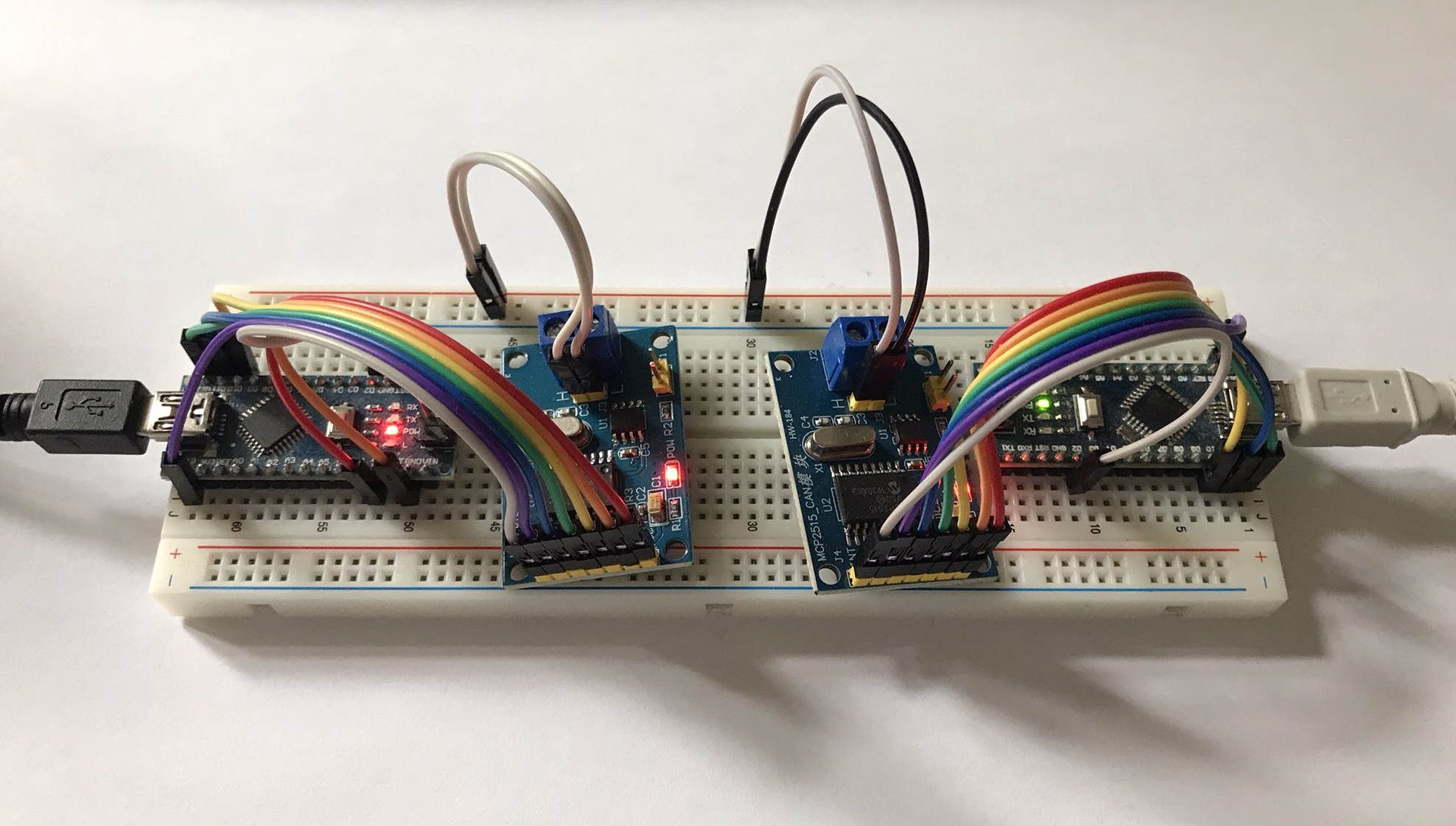
    MySensors_CAN.jpg

    I will use the demo sketches from Adam's fork. Let you know how it works for me.


  • @JeeLet

    what do you want me to test ????

    bool transportSanityCheck(void)
    {
    	return (CAN0.getError()==CAN_OK)
    }
    

    The "radio guy" opinion would be great.
    ((I'll look for possible help ). )

    I'm not a "radio guy", but I think this code change looks fine. When sanity check fails then MySensors core calls transportInit() which would try to re-initialise the MCP2515 module.

    In my setup with only 2 CAN modules I'm afraid this will always return CAN_OK. So no idea how to check this. May be unplug the both CAN wires?


  • @Adam-Slowik, @JeeLet Ok, with the both sketches it works with some limitations.
    Nice work so far - thank you for contributing!

    I have done some modifications in the CAN transport files.
    @Adam-Slowik I would like to create a PR in your forked repo. Then we can discuss the code changes in GitHub. Would that be Ok for you - do you have time for this?

    One limitation I found so far are long MyMessages. They can be up to 32 byte - which results in up to 4 CAN-Bus sub telegrams. When I send 32 byte message I observed the sub telegrams do not always arrive in send order in MyTransportCAN.cpp like this:

    19916 CAN:RCV:CANH=2202010368,ID=3,TOTAL=4,CURR=0,TO=3,FROM=0
    19921 CAN:RCV:LN=8,DTA0=0,DTA1=0,DTA2=3,DTA3=202,DTA4=9,DTA5=2,DTA6=0,DTA7=49
    19929 CAN:RCV:SLOT=0,PART=1
    19932 CAN:RCV:CANH=2202075904,ID=3,TOTAL=4,CURR=1,TO=3,FROM=0
    19937 CAN:RCV:LN=8,DTA0=50,DTA1=51,DTA2=52,DTA3=53,DTA4=54,DTA5=55,DTA6=56,DTA7=57
    19945 CAN:RCV:SLOT=0,PART=2
    19947 CAN:RCV:CANH=2202206976,ID=3,TOTAL=4,CURR=3,TO=3,FROM=0
    19953 CAN:RCV:LN=8,DTA0=56,DTA1=57,DTA2=48,DTA3=49,DTA4=50,DTA5=51,DTA6=52,DTA7=53
    19960 !CAN:RCV:proper slot not found
    19964 CAN:RCV:CANH=2202141440,ID=3,TOTAL=4,CURR=2,TO=3,FROM=0
    19970 CAN:RCV:LN=8,DTA0=48,DTA1=49,DTA2=50,DTA3=51,DTA4=52,DTA5=53,DTA6=54,DTA7=55
    19978 CAN:RCV:SLOT=0,PART=3
    

    Sub telegram 3 arrives before 2.
    I'm afraid the function _findCanPacketSlot() needs an update to handle this.
    @Adam-Slowik Do you see a chance for you to update the logic next time?

    Other limitation I see is the limited CAN telegram buffer of 3 packets in the MCP2515 module. I'm afraid for reliable operation with MySensors a change from polling to interrupt mode is required.
    But this can be done later, after the fix for the PacketSlot logic.


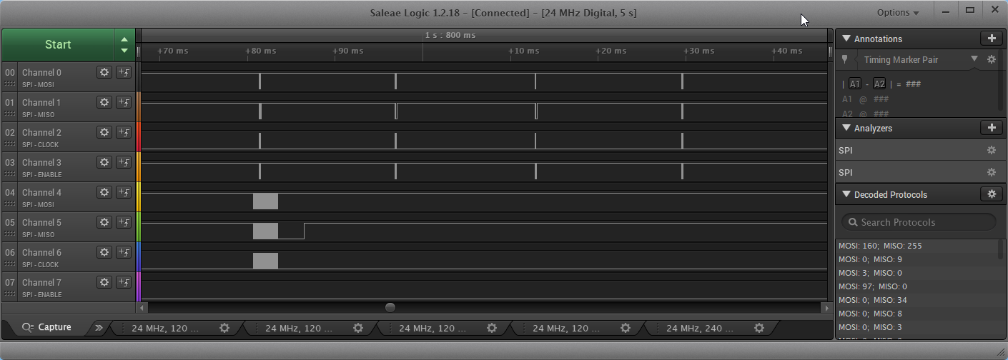
  • In logic analyser it looks like this:
    5cadf202-a379-4b38-beaa-1a0d34eb60ab-image.png
    Upper 4 channels are from node, lower ones are from gateway.

    Close up from gateway send (4 packets):
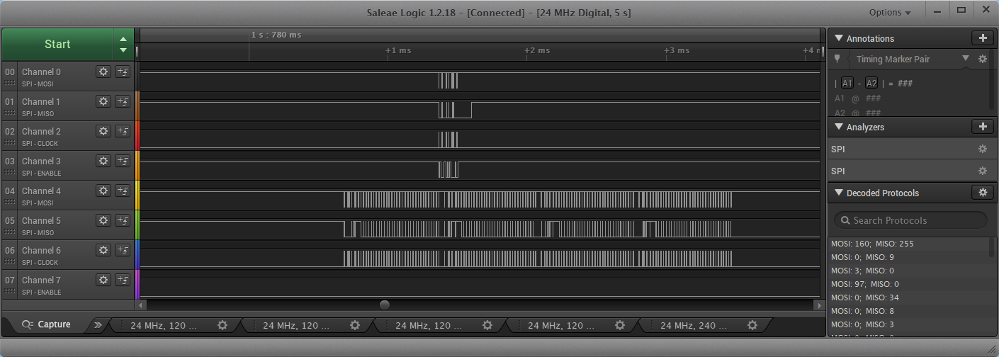
    1fa3bfdb-48df-4ffd-a017-350a7b7dae71-image.png


  • @virtualmkr said in CAN bus transport implementation:

    I'm not a "radio guy", but I think this code change looks fine. When sanity check fails then MySensors core calls transportInit() which would try to re-initialise the MCP2515 module.

    Ok. I'll update code.

    @virtualmkr said in CAN bus transport implementation:

    I have done some modifications in the CAN transport files.
    @Adam-Slowik I would like to create a PR in your forked repo. Then we can discuss the code changes in GitHub. Would that be Ok for you - do you have time for this?

    Sure. Make PR. I'll try to review it within 48h.

    @virtualmkr said in CAN bus transport implementation:

    When I send 32 byte message I observed the sub telegrams do not always arrive in send order

    Other limitation I see is the limited CAN telegram buffer of 3 packets in the MCP2515 module. I'm afraid for reliable operation with MySensors a change from polling to interrupt mode is required.

    I think this two issues are linked. Now packets are sent in correct order (could You verify it?). If packets are sent in short periods We should use interrupt to keep MCP2515 buffers empty. When We fail to keep buffers empty (due to polling mechanism) We receive sub telegrams in mixed order. This theory could be true if MCP2515 buffers are implemented as LIFO. I'll look into documentation to figure it out.
    Anyway both fixes are worth to implement. I'll try to do this over weekend.


  • Hello
    CAN Bus is still functional, and no problem.

    a question : is it possible to implement the use of 2 CAN Module on the same Gateway.
    2 CAN bus or RS485 + CAN

    as for the RS485 in example for a Mega2560 board

    MyConfig.h
    ......
     * Example: @code #define MY_RS485_HWSERIAL Serial1 @endcode
     */
    //#define MY_RS485_HWSERIAL (Serial1)
    

Log in to reply
 

Suggested Topics

42
Online

11.5k
Users

11.1k
Topics

112.7k
Posts