Which pins should I use for status led on a wemos d1 mini gateway
-
Wow, thank you everyone! I have all the leds sink to 5v (long leg) and I was going to put a resistor on the other leg to connect them to the gpio because that is what it says on the docs, but docs are for arduino. I'm very happy that it's the same for the D1 mini. When I define the pins on the sketch should I use the same label (without the D) or should I use a different value?
By the way, what can be the i2c used on the gateway?
OH, and which resistor should I use? Does it need to be of an specific value or is it enough if it is within certain range? -
@pw44 No, this isn't a good idea. You should have all status LEDs in either source or sink configuration, or some LEDs will be inverted (lit by default, off when there is activity).
D3 and D4 must to be connected like this to not prevent the ESP from booting: GPIO - Resistor - LED cathode - LED anode - VCC. D0 should be connected equally, even if it doesn't matter for the ESP's functionality.
Besides that, if you don't use I2C, you should also be able to use D1 (GPIO5) and D2 (GPIO4) for status LEDs, inclusion mode button, etc.
@BearWithBeard said in Which pins should I use for status led on a wemos d1 mini gateway:
@pw44 No, this isn't a good idea. You should have all status LEDs in either source or sink configuration, or some LEDs will be inverted (lit by default, off when there is activity).
D3 and D4 must to be connected like this to not prevent the ESP from booting: GPIO - Resistor - LED cathode - LED anode - VCC. D0 should be connected equally, even if it doesn't matter for the ESP's functionality.
Besides that, if you don't use I2C, you should also be able to use D1 (GPIO5) and D2 (GPIO4) for status LEDs, inclusion mode button, etc.
Thank you so much for your answer. Helped me a lot.
-
Wow, thank you everyone! I have all the leds sink to 5v (long leg) and I was going to put a resistor on the other leg to connect them to the gpio because that is what it says on the docs, but docs are for arduino. I'm very happy that it's the same for the D1 mini. When I define the pins on the sketch should I use the same label (without the D) or should I use a different value?
By the way, what can be the i2c used on the gateway?
OH, and which resistor should I use? Does it need to be of an specific value or is it enough if it is within certain range?@pw44 I'm glad I could help!
@Danielo-Rodríguez said in Which pins should I use for status led on a wemos d1 mini gateway:
By the way, what can be the i2c used on the gateway?
You could add any kind of I2C device to it, like a temperature sensor. A gateway is basically a regular node with some (important) extra functionality. Just be mindful to not overburden the gateway with too many secondary tasks. If it spends too much time dealing with sensors and other stuff blocking the loop, you may risk that it misses incoming messages.
OH, and which resistor should I use? Does it need to be of an specific value or is it enough if it is within certain range?
You can sink up to 20mA into a pin on the ESP8266. As long as you stay below that (and the current limit of the LEDs), you should be fine [R = (VCC - Vforward) / Iforward].
220R or 330R is fine for a bright light. Use 1K or even more if you prefer a rather dim light. Or anything in between. If you connect the LEDs to 3.3V instead of 5V, you need smaller resistors for the same brightness.
-
@pw44 I'm glad I could help!
@Danielo-Rodríguez said in Which pins should I use for status led on a wemos d1 mini gateway:
By the way, what can be the i2c used on the gateway?
You could add any kind of I2C device to it, like a temperature sensor. A gateway is basically a regular node with some (important) extra functionality. Just be mindful to not overburden the gateway with too many secondary tasks. If it spends too much time dealing with sensors and other stuff blocking the loop, you may risk that it misses incoming messages.
OH, and which resistor should I use? Does it need to be of an specific value or is it enough if it is within certain range?
You can sink up to 20mA into a pin on the ESP8266. As long as you stay below that (and the current limit of the LEDs), you should be fine [R = (VCC - Vforward) / Iforward].
220R or 330R is fine for a bright light. Use 1K or even more if you prefer a rather dim light. Or anything in between. If you connect the LEDs to 3.3V instead of 5V, you need smaller resistors for the same brightness.
@BearWithBeard Thank you very much!
I'll do that -
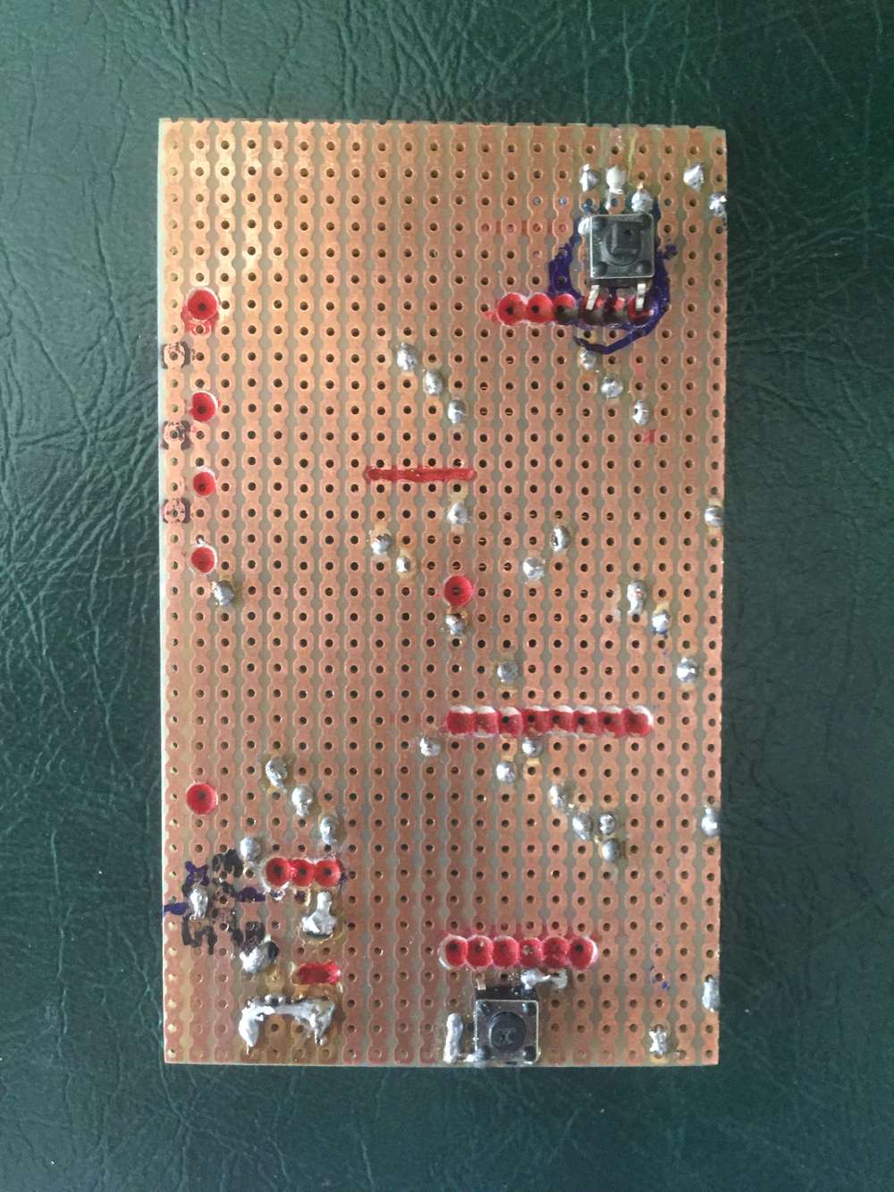
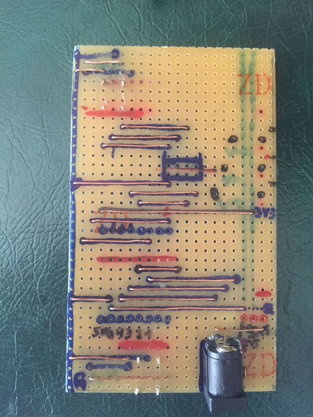
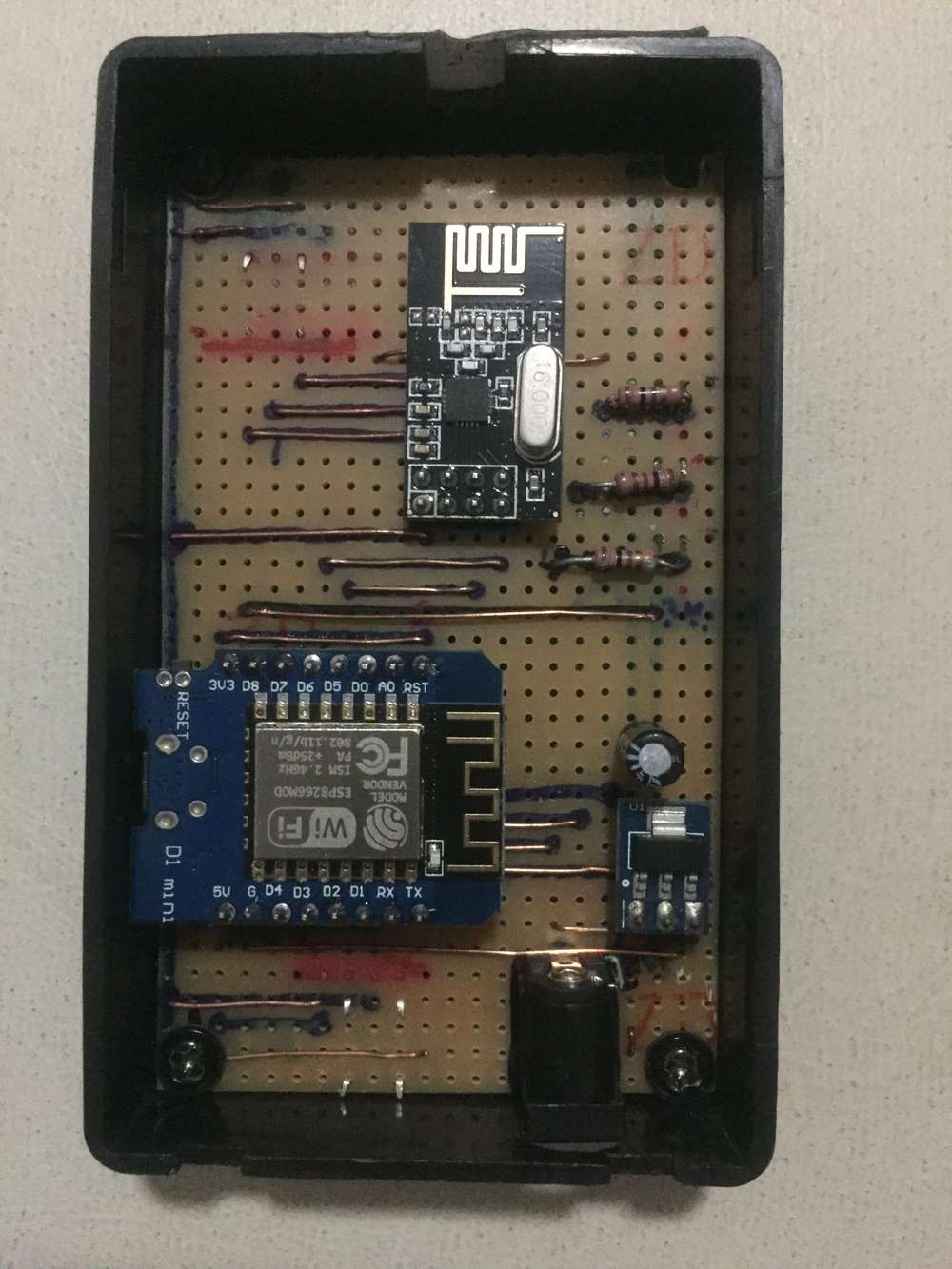
At the end I was able to use D0,D1 and D4 for status leds. Something interesting is that I can use the actual
DNnomenclature because there is a header file that maps them properly. The weird thing is that such file is arduino.h (I'm using platformio) so I'm not sure if it is specific for the D1 mini or if D1 is compatible with arduino pinout.
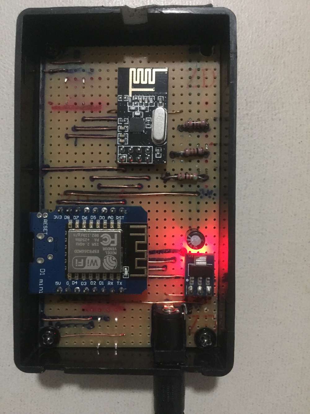
I used a 220 ohm resistor and, dam it, the leds are bright as hell, haha.
Everything is working now, it's very pleasant to see the leds blink when I turn on other node. Thanks to all the people on this forum for the great support. -
@pw44 No, this isn't a good idea. You should have all status LEDs in either source or sink configuration, or some LEDs will be inverted (lit by default, off when there is activity).
D3 and D4 must to be connected like this to not prevent the ESP from booting: GPIO - Resistor - LED cathode - LED anode - VCC. D0 should be connected equally, even if it doesn't matter for the ESP's functionality.
Besides that, if you don't use I2C, you should also be able to use D1 (GPIO5) and D2 (GPIO4) for status LEDs, inclusion mode button, etc.
@BearWithBeard could you please confirm the correct definitions for the pins?
#define MY_DEFAULT_ERR_LED_PIN 3 // D0 Error led pin
#define MY_DEFAULT_RX_LED_PIN 5 // D3 Receive led pin
#define MY_DEFAULT_TX_LED_PIN 4 // D4 Transmit led pinD1 = pin 1
D3 = pin 5
D4 = pin 4
D0 = pin 3is this correct?
thx in advance.
-
@pw44 could you clarify what pin numbers you are referring to, perhaps with a picture?
The mapping used by the Arduino IDE can be seen at https://github.com/esp8266/Arduino/blob/master/variants/d1_mini/pins_arduino.h#L37
@mfalkvidd thx for answering.
i was looking for the correct mapping for:
#define MY_DEFAULT_ERR_LED_PIN D0 // Error led pin
#define MY_DEFAULT_RX_LED_PIN D3 // Receive led pin
#define MY_DEFAULT_TX_LED_PIN D4 // Transmit led pinthx to your hint, D0 =16, D3 = 0, D4 = 2.
So, i shall change to:
#define MY_DEFAULT_ERR_LED_PIN 16 // Error led pin
#define MY_DEFAULT_RX_LED_PIN 0 // Receive led pin
#define MY_DEFAULT_TX_LED_PIN 2 // Transmit led pin -
@BearWithBeard could you please confirm the correct definitions for the pins?
#define MY_DEFAULT_ERR_LED_PIN 3 // D0 Error led pin
#define MY_DEFAULT_RX_LED_PIN 5 // D3 Receive led pin
#define MY_DEFAULT_TX_LED_PIN 4 // D4 Transmit led pinD1 = pin 1
D3 = pin 5
D4 = pin 4
D0 = pin 3is this correct?
thx in advance.
@pw44 If you are using the "big" WeMos D1 - the one in the shape of an Arduino Uno - then yes, that looks right to me. This file contains the pin definitions used for this board. But you may have to wire the LEDs to different pins in this case, because D4 / GPIO4 conflicts with the default assignment for CE when using an NRF24 transceiver and D3 / GPIO5 conflicts with DIO0 when using an RFM radio according to the Connecting the Radio guide.
If you want to try using the same GPIOs that worked for me on the NodeMCU (2, 4 and 16), you may connect the LEDs to D9, D14 and D2.
You may also want to read the book that @mfalkvidd recommended or take a look at this ESP8266 pinout reference to see what pin does what.
The D1 mini - the board that the OP uses - has different pin definitions, which are listed here and are similar to the NodeMCU I was using.
In general, I think it should be fine to use the alias D1, D2, etc for the pins. No need to use the GPIO number here.
-
@BearWithBeard exactly what i was looking for, the pin mapping for D1 MINI.
Thx!
Hello! It looks like you're interested in this conversation, but you don't have an account yet.
Getting fed up of having to scroll through the same posts each visit? When you register for an account, you'll always come back to exactly where you were before, and choose to be notified of new replies (either via email, or push notification). You'll also be able to save bookmarks and upvote posts to show your appreciation to other community members.
With your input, this post could be even better 💗
Register Login