Gateway device
-
Just learned a lesson the hard way, the last couple of days.. Discovered that I hadn't read the datasheet for the atsamd21 good enough, so I had connected all the PINS for the SPI / UARTs completely wrong. Which means 10-12 connections that was wrong (the board uses 3 SPI ports and 2 UARTs, one SPI doubles as UART, depending on the network interface connected)
So new boards are in the pipeline from dirtypcbs.com
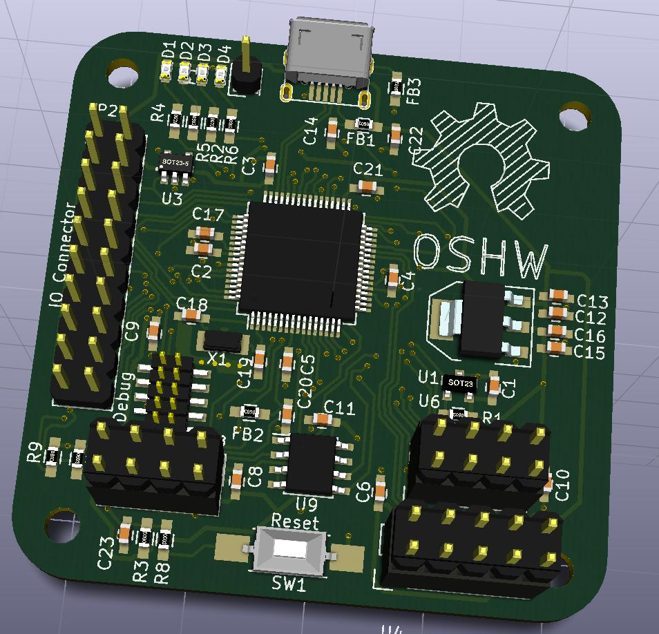
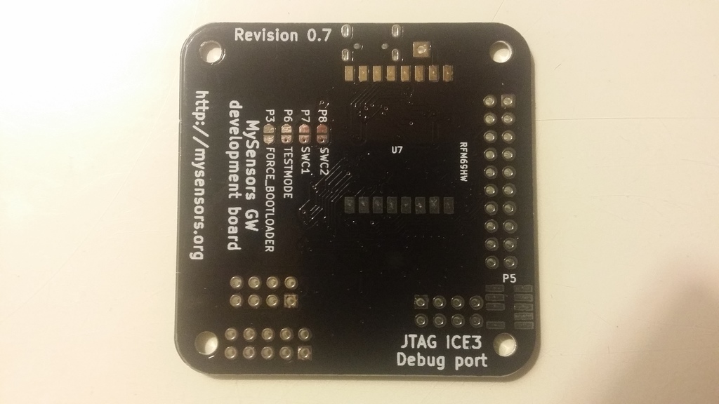
This is btw improved on a couple of other points, compared to the previous board. Biggest is, that it now has 4 x 3mm mounting holes, (happy now @ServiceXp ? :)). It also got a couple of extra solder jumpers on the backside, that could be used for software configurations, or test points.
-
@tbowmo: what a bad luck! but it is so easy to miss something when you look at the datasheet size :wink:
I hope you will get it working like you want, I am sure :smiley:
I like your enlarged pads for 0402. Is it easier to solder like this? Do you handsolder it? Do you think using 0603/0805 with no enlarged pads would take same place???I am asking this for my future designs, in case. But 0402 is so small... -
atsamd21 comes in 3 variants, with 32, 48 og 64 pins (If I remember right). I'm using the 64 pin variant
If things go well with this one, then I might make a sensebender micro 2, with an 32 pin atsamd20 (almost the same as d21, but without USB host/slave capabilities)
-
Just learned a lesson the hard way, the last couple of days.. Discovered that I hadn't read the datasheet for the atsamd21 good enough, so I had connected all the PINS for the SPI / UARTs completely wrong. Which means 10-12 connections that was wrong (the board uses 3 SPI ports and 2 UARTs, one SPI doubles as UART, depending on the network interface connected)
So new boards are in the pipeline from dirtypcbs.com
This is btw improved on a couple of other points, compared to the previous board. Biggest is, that it now has 4 x 3mm mounting holes, (happy now @ServiceXp ? :)). It also got a couple of extra solder jumpers on the backside, that could be used for software configurations, or test points.
-
atsamd21 comes in 3 variants, with 32, 48 og 64 pins (If I remember right). I'm using the 64 pin variant
If things go well with this one, then I might make a sensebender micro 2, with an 32 pin atsamd20 (almost the same as d21, but without USB host/slave capabilities)
-
@ServiceXp
I just received the PCBs for the second prototype spin yesterday, the first spin had too many errors in the routing around SPI / UARTS so I decided to ditch it, and do a second spin. Dirtypcbs got some hickups processing my gerbers but finaly made the boards.
I hope that I can get around to assemble one this weekend, but I can't promise anything, as I have been loaded more than 150% with work (both from my employer, and from the wife).
-
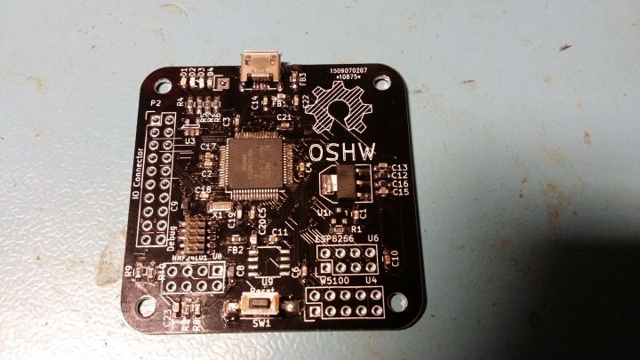
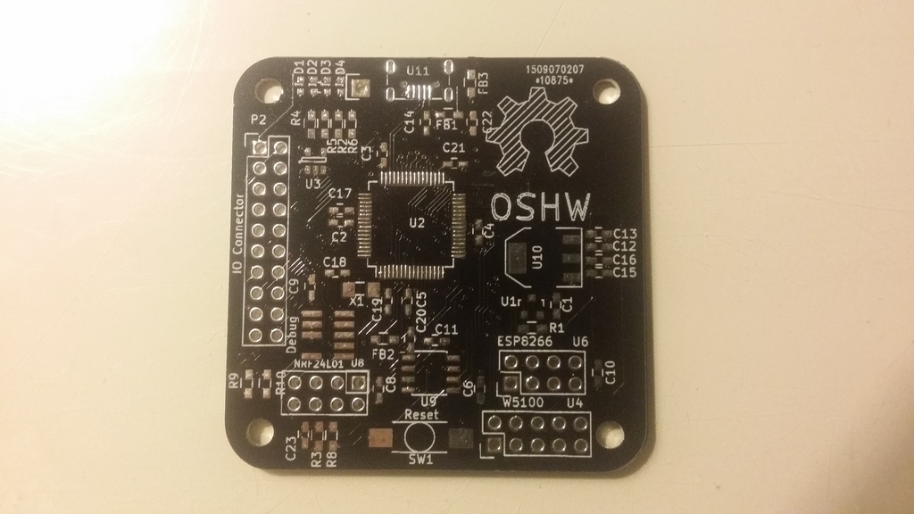
Images of the latest pcb's (Before SMD assembly)
Unfortunately I "injured" my back today (aah, maybe not injured, but feels like it :() so I'm on strong medics to keep the pain away. That means that didn't get around to do the SMD assembly today as I planned, as I can't sit at the desk for a longer time.. hope that it gets better during the weekend.
-
yeah :smile:
-
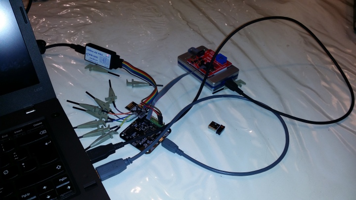
A small update before I hit the bed tonight..
I've got radio up and running on the SAMD, and got the first message from one of my sensebender micros through to my pc.
It's still in debug mode, using a serial port on the samd as output (And my logic analyzer to decode the serial stream). So no ethernet / wifi or the like up yet.
The next step will be to have it use USB instead of the serial port..
-
:+1: good work!
-
Great! I will buy one of these as soon as this is working as you want :)