Did you buy a Fibaro keyfob has it fallen to pieces? well this might interest you. A eight keys keyfob ip68 rated
-
Hi fellow mysensors people :)
I have been working on a project , might need a bit of guidance to finish this off (with the sketch)
Ok lets start with what I have been doing , plus some researchingRight who of you purchased Fibaro_keyfob ??? that very reliable and ruggedized key fob
well yes I did too , it was approx. 45 pounds how long did it last ?? hmm 12 months or so
you also need a Aeotec_z-stick_gen5 to link it to domoticz .It might look nice,, but really in my option was not fit for purpose poor design
at high price !!!.
The Fibaro you have to use a large coin to open and replace the battery ,,,,the connectors inside well weak!! not long and its buggered .. oh I’ll go and buy another at 45 ponds naaaaa!!!!
rinse and repeat every 12 months or so naaaa!!!!
you also needed a Aeotec_z-stick_gen5 to connect to domoitcz. As said.Why would I do this since nowhere days we have voice control etc..
well for me it’s a universal way of switching off quite few things at once etc,,So what was the alternative’s ???? ok
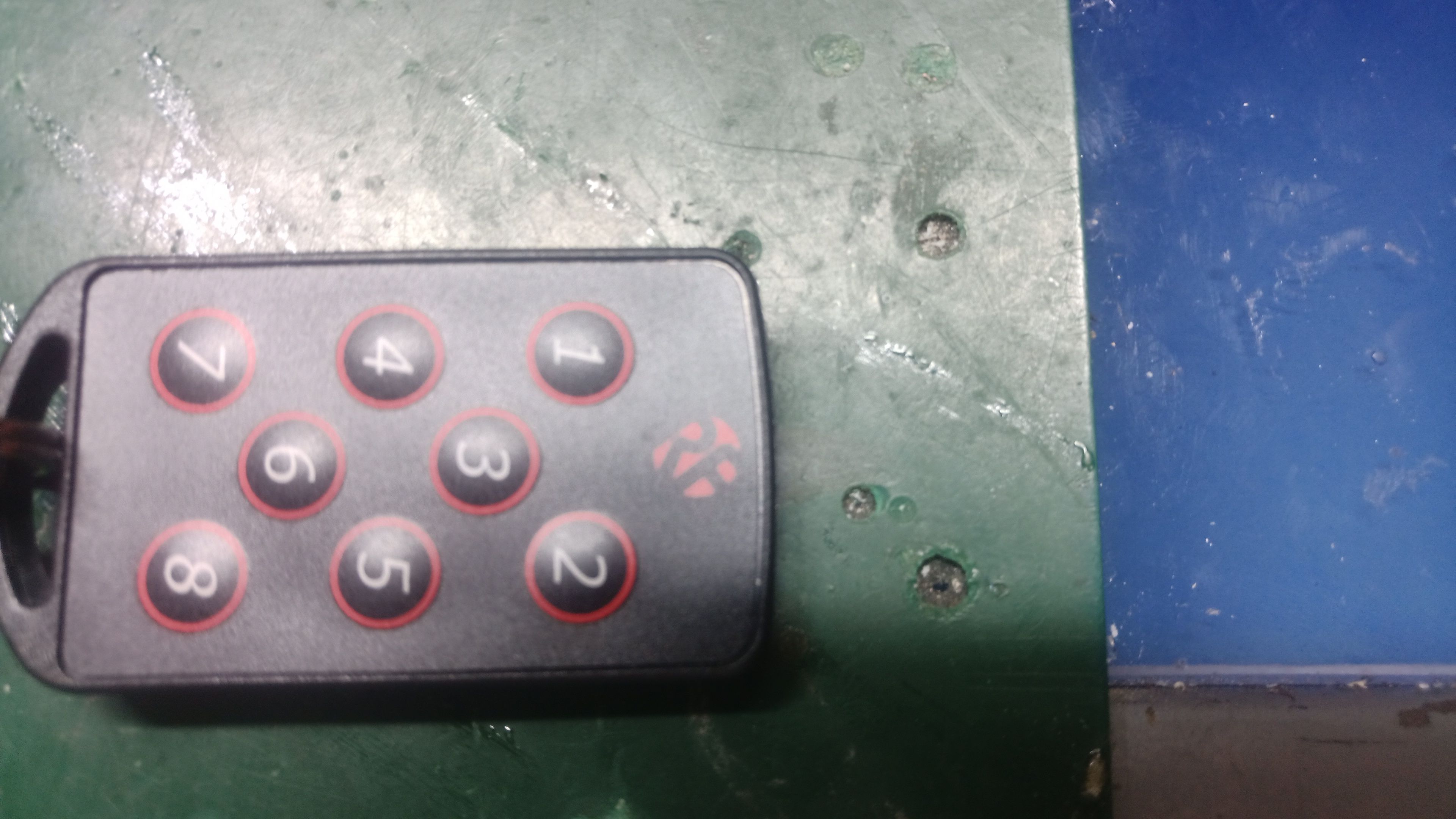
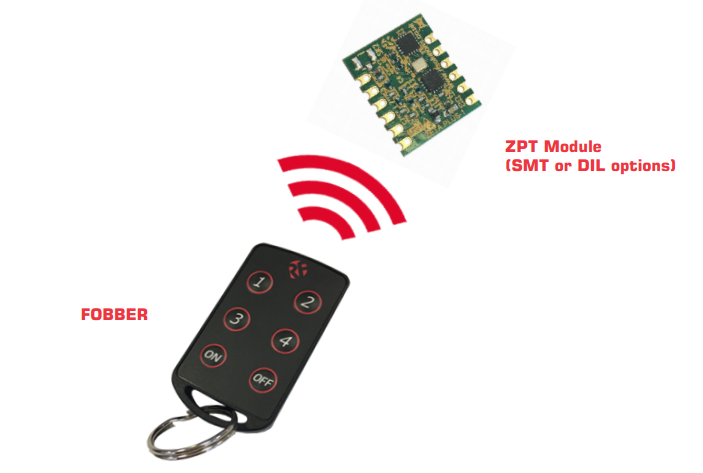
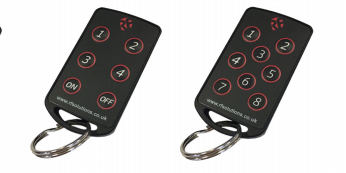
Well firstly most key fobs I have found are only 4 keys I wanted few more than that
in the end I came up with the key fob in first picture a ( rf solutions) key fob ip68 rated helpful might last past 12 months ,ok , now at this point I thought oh err use rflink to pick up signals job done But naaa it does not sense them , so if you want try this then rflick is not ganna cut it unfortunately .
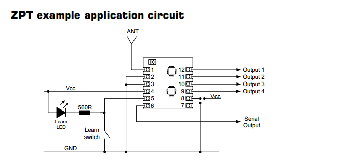
So then you need its receiver module ie ..>>>
Telemetry module that in my case at 443mz frequency . be sure to get a receiver module that matches the key fobs transmitting frequency ( I did not need to tell you that did I :) )
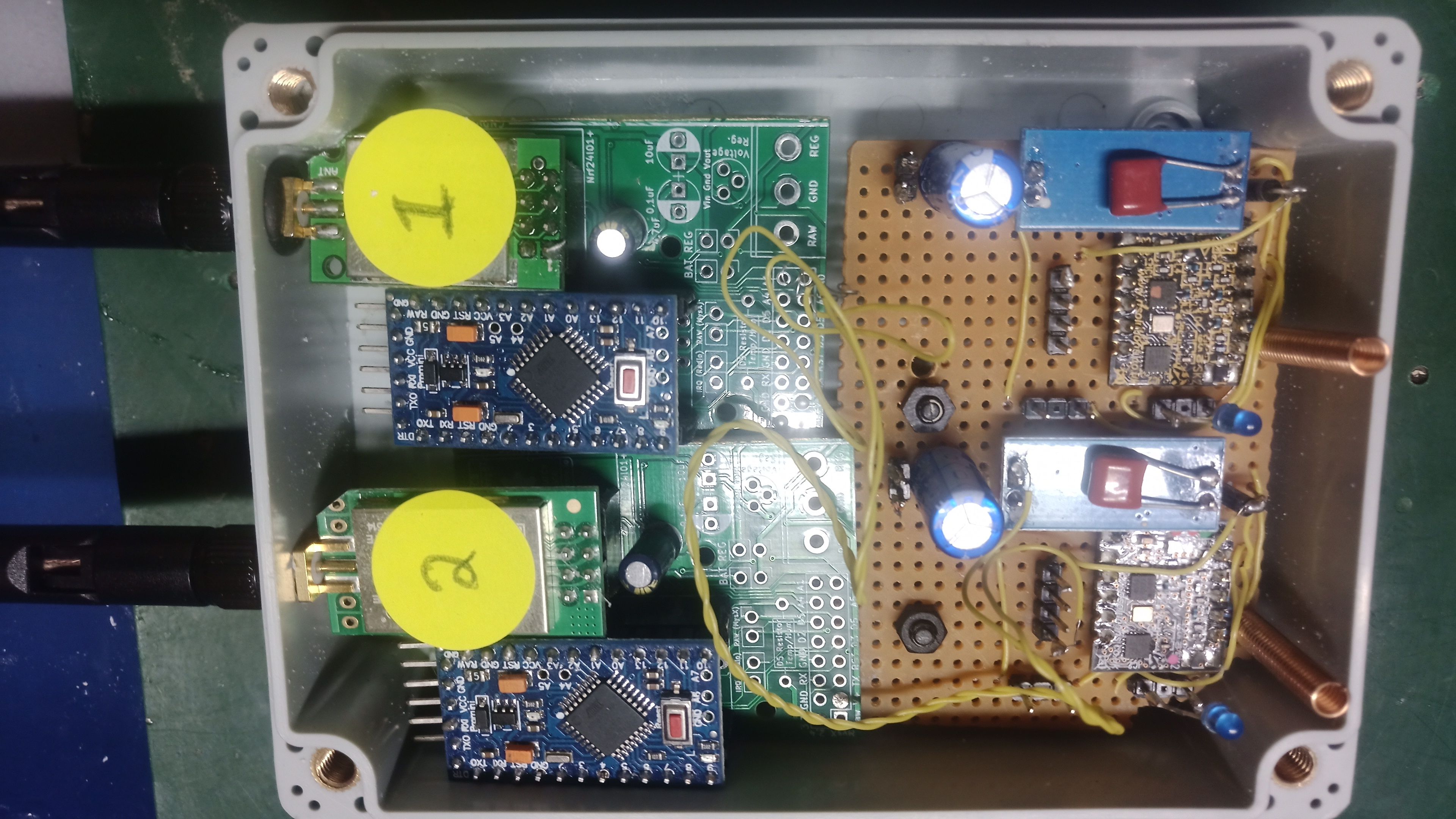
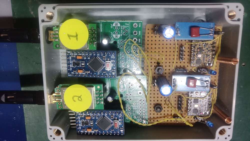
Ok so the second picture is of the receiver module really not that hard really!!! .
My soldering will just about passes put quite a few caps in to stabilise the power as best as possible .
As you can see the telemetry modules are on the left and the mysensors (2) on the right .
I picked up a program from another project and modified it so that hopefully it would pick up four inputs on each unit
mini pro The sketch presented here is the modified sketch with 4 inputs
but one input works and the other inputs are temperamental
any suggestions or guidance for interfacing this with modules would be nice .** Oh these receiver units like 3.6 volts so keep the voltage down
roughly 33 quid for key fob
11 pounds for each receiver unit ,,,you will need 2 for the eight key fob unit
 image url))

-
Hi fellow mysensors people :)
I have been working on a project , might need a bit of guidance to finish this off (with the sketch)
Ok lets start with what I have been doing , plus some researchingRight who of you purchased Fibaro_keyfob ??? that very reliable and ruggedized key fob
well yes I did too , it was approx. 45 pounds how long did it last ?? hmm 12 months or so
you also need a Aeotec_z-stick_gen5 to link it to domoticz .It might look nice,, but really in my option was not fit for purpose poor design
at high price !!!.
The Fibaro you have to use a large coin to open and replace the battery ,,,,the connectors inside well weak!! not long and its buggered .. oh I’ll go and buy another at 45 ponds naaaaa!!!!
rinse and repeat every 12 months or so naaaa!!!!
you also needed a Aeotec_z-stick_gen5 to connect to domoitcz. As said.Why would I do this since nowhere days we have voice control etc..
well for me it’s a universal way of switching off quite few things at once etc,,So what was the alternative’s ???? ok
Well firstly most key fobs I have found are only 4 keys I wanted few more than that
in the end I came up with the key fob in first picture a ( rf solutions) key fob ip68 rated helpful might last past 12 months ,ok , now at this point I thought oh err use rflink to pick up signals job done But naaa it does not sense them , so if you want try this then rflick is not ganna cut it unfortunately .
So then you need its receiver module ie ..>>>
Telemetry module that in my case at 443mz frequency . be sure to get a receiver module that matches the key fobs transmitting frequency ( I did not need to tell you that did I :) )
Ok so the second picture is of the receiver module really not that hard really!!! .
My soldering will just about passes put quite a few caps in to stabilise the power as best as possible .
As you can see the telemetry modules are on the left and the mysensors (2) on the right .
I picked up a program from another project and modified it so that hopefully it would pick up four inputs on each unit
mini pro The sketch presented here is the modified sketch with 4 inputs
but one input works and the other inputs are temperamental
any suggestions or guidance for interfacing this with modules would be nice .** Oh these receiver units like 3.6 volts so keep the voltage down
roughly 33 quid for key fob
11 pounds for each receiver unit ,,,you will need 2 for the eight key fob unit
)
@mutantx
I am seeming to have problems with the sketch ,heres is the modified sketch any guidance appreciated ./** The MySensors Arduino library handles the wireless radio link and protocol between your home built sensors/actuators and HA controller of choice. The sensors forms a self healing radio network with optional repeaters. Each repeater and gateway builds a routing tables in EEPROM which keeps track of the network topology allowing messages to be routed to nodes. Created by Henrik Ekblad <henrik.ekblad@mysensors.org> Copyright (C) 2013-2015 Sensnology AB Full contributor list: https://github.com/mysensors/Arduino/graphs/contributors Documentation: http://www.mysensors.org Support Forum: http://forum.mysensors.org This program is free software; you can redistribute it and/or modify it under the terms of the GNU General Public License version 2 as published by the Free Software Foundation. ******************************* DESCRIPTION Simple binary switch example updated for 2 switches Connect button or door/window reed switch between digitial I/O pin 3 (BUTTON_PIN below) and GND. http://www.mysensors.org/build/binary */ // Enable debug prints to serial monitor #define MY_DEBUG // Enable and select radio type attached #define MY_RADIO_NRF24 //#define MY_RADIO_RFM69 #include <MySensors.h> #include <SPI.h> #include <Bounce2.h> #define CHILD_ID1 3 #define BUTTON_PIN1 3 // Arduino Digital I/O pin for button/reed switch #define CHILD_ID2 4 #define BUTTON_PIN2 4 // Arduino Digital I/O pin for button/reed switch #define CHILD_ID3 5 #define BUTTON_PIN3 5 // Arduino Digital I/O pin for button/reed switch #define CHILD_ID4 6 #define BUTTON_PIN4 6 // Arduino Digital I/O pin for button/reed switch Bounce debouncer1 = Bounce(); Bounce debouncer2 = Bounce(); // debouncer for the second switch Bounce debouncer3 = Bounce(); // debouncer for the third switch Bounce debouncer4 = Bounce(); // debouncer for the forth switch int oldValue1= -1; int oldValue2= -1; // second switch needs to have it's own old state int oldValue3= -1; // second switch needs to have it's own old state int oldValue4= -1; // second switch needs to have it's own old state // Change to V_LIGHT if you use S_LIGHT in presentation below MyMessage msg1(CHILD_ID1,V_TRIPPED),msg2(CHILD_ID2,V_TRIPPED),msg3(CHILD_ID3,V_TRIPPED),msg4(CHILD_ID4,V_TRIPPED); void setup() { // Setup the button pinMode(BUTTON_PIN1,INPUT_PULLUP ); // You can assign pinmode and use pullup in one statement. pinMode(BUTTON_PIN2,INPUT_PULLUP); pinMode(BUTTON_PIN3,INPUT_PULLUP); pinMode(BUTTON_PIN4,INPUT_PULLUP); // Activate internal pull-up // digitalWrite(BUTTON_PIN1,HIGH); // digitalWrite(BUTTON_PIN2,HIGH); // digitalWrite(BUTTON_PIN3,HIGH); // digitalWrite(BUTTON_PIN4,HIGH); // After setting up the button, setup debouncer1 debouncer1.attach(BUTTON_PIN1); debouncer1.interval(5); debouncer2.attach(BUTTON_PIN2); debouncer2.interval(5); debouncer3.attach(BUTTON_PIN3); debouncer3.interval(5); debouncer4.attach(BUTTON_PIN4); debouncer4.interval(5); // Register binary input sensor to gw (they will be created as child devices) // You can use S_DOOR, S_MOTION or S_LIGHT here depending on your usage. // If S_LIGHT is used, remember to update variable type you send in. See "msg" above. present(CHILD_ID1, S_DOOR); present(CHILD_ID2, S_DOOR); present(CHILD_ID3, S_DOOR); present(CHILD_ID4, S_DOOR); } // Check if digital input has changed and send in new value void loop() { // Check if the first switch state has changed debouncer1.update(); // Get the update value int value = debouncer1.read(); if (value != oldValue1) { // Send in the new value send(msg1.set(value==HIGH ? 1 : 0)); // send(msg2.set(value==HIGH ? 1 : 0)); // this is where you turn the second switch in your controller // send(msg3.set(value==HIGH ? 1 : 0)); // this is where you turn the third switch in your controller oldValue1 = value; } // Check if the 2nd switch state has changed debouncer2.update(); // Get the update value value = debouncer2.read(); // no need to redeclare it (I removed int) if (value != oldValue2) { // Send in the new value // send(msg1.set(value==HIGH ? 1 : 0)); send(msg2.set(value==HIGH ? 1 : 0)); // this is where you turn the second switch in your controller // send(msg3.set(value==HIGH ? 1 : 0)); // this is where you turn the third switch in your controller oldValue2 = value; } // Check if the third switch state has changed debouncer3.update(); // Get the update value value = debouncer3.read(); // no need to redeclare it (I removed int) if (value != oldValue3) { // Send in the new value // send(msg1.set(value==HIGH ? 1 : 0)); // send(msg2.set(value==HIGH ? 1 : 0)); // this is where you turn the second switch in your controller send(msg3.set(value==HIGH ? 1 : 0)); // this is where you turn the third switch in your controller oldValue3 = value; } // Check if the forth switch state has changed debouncer4.update(); // Get the update value value = debouncer4.read(); // no need to redeclare it (I removed int) if (value != oldValue4) { // Send in the new value // send(msg1.set(value==HIGH ? 1 : 0)); // send(msg2.set(value==HIGH ? 1 : 0)); // this is where you turn the second switch in your controller send(msg4.set(value==HIGH ? 1 : 0)); // this is where you turn the forth switch in your controller oldValue4 = value; } } -
Update !!!! all fixed and working with domoticz
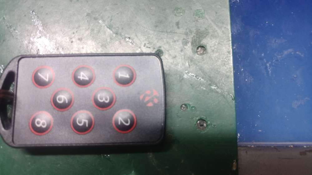
I used FOBBER-8T8 please google it approx. 20 quid compared to 45 pounds for fibaro keyfob
A) updated the sketch to allow 4 inputs s all fine
B) Symmetric really so from the top two pictures from the left the telemetry modules on the Vero board (total of 8 outputs ) passed across to two mysensors modules with 4 inputs on each unit I used 4016 cmos switches to pair outputs with inputs and It worked !!! .
So the ip 68 keyfob transmits to the telemetry modules which then output to the inputs of the sensors that
domoticz can pick up . add to blocky script can do what you want
Any help with This would be much applicated
https://forum.mysensors.org/topic/11886/and-for-my-next-trick-project-i-mean-m5stamp-pico-any-body-playing-with-these-yet-battery-operated-mp3-unit/2?_=1642356371902 -
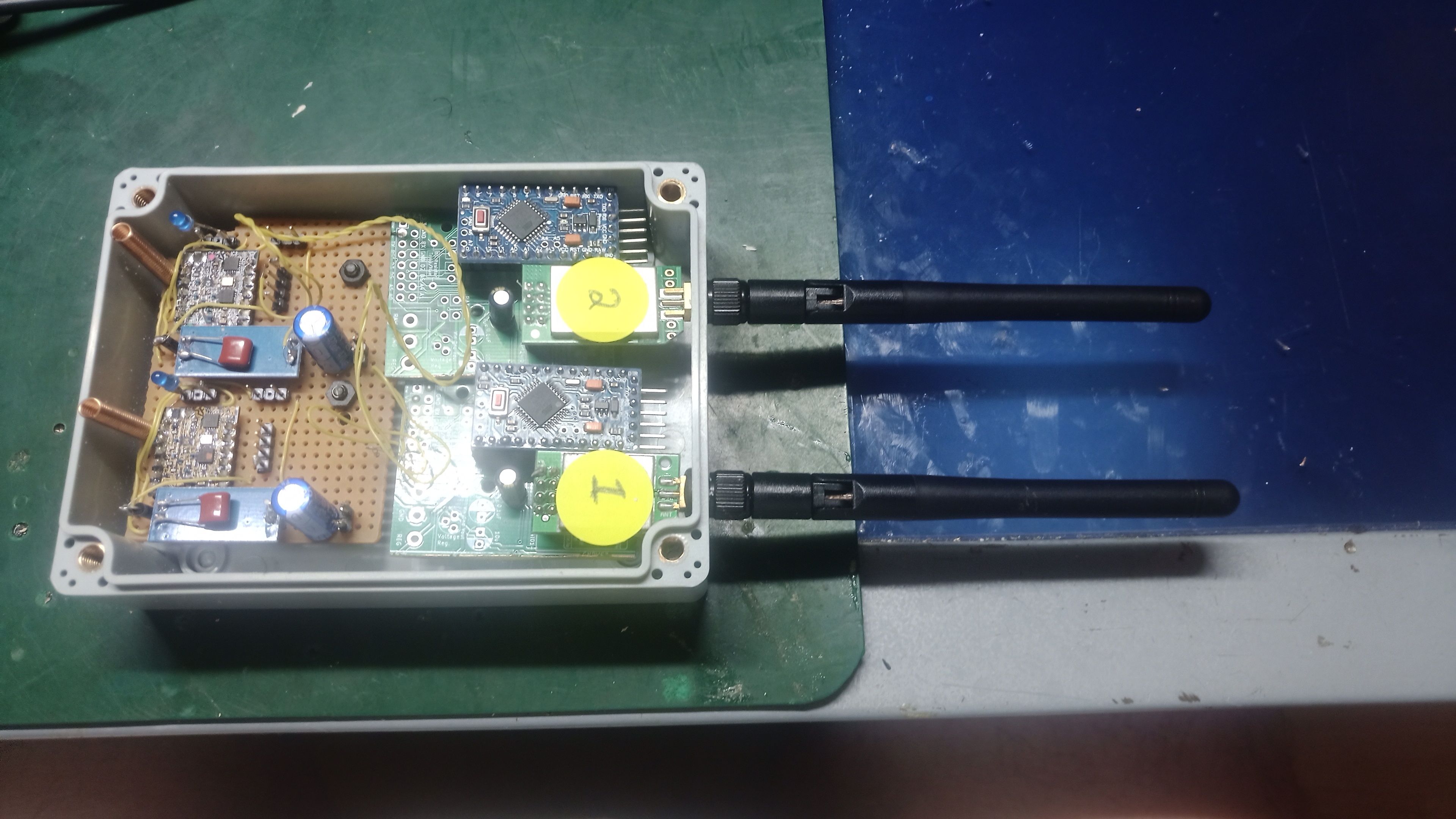
And here's the completed unit I have not really tested the range yet ,
but should be good , the receiver units (telemetry units) can work in latching mode and in push button mode easy
I am pretty sure this setup will last longer than fibrio key fob , easy to pair receiver with key fob
I have 3 key fobs ,, yes why ??? well they will break and I rather purchase few ,for an investment for the futureMaybe some can help me with other project the stamp m5 pico trying to program it is a standard switch node
https://forum.mysensors.org/topic/11886/and-for-my-next-trick-project-i-mean-m5stamp-pico-any-body-playing-with-these-yet-battery-operated-mp3-unit/2?_=1642356371902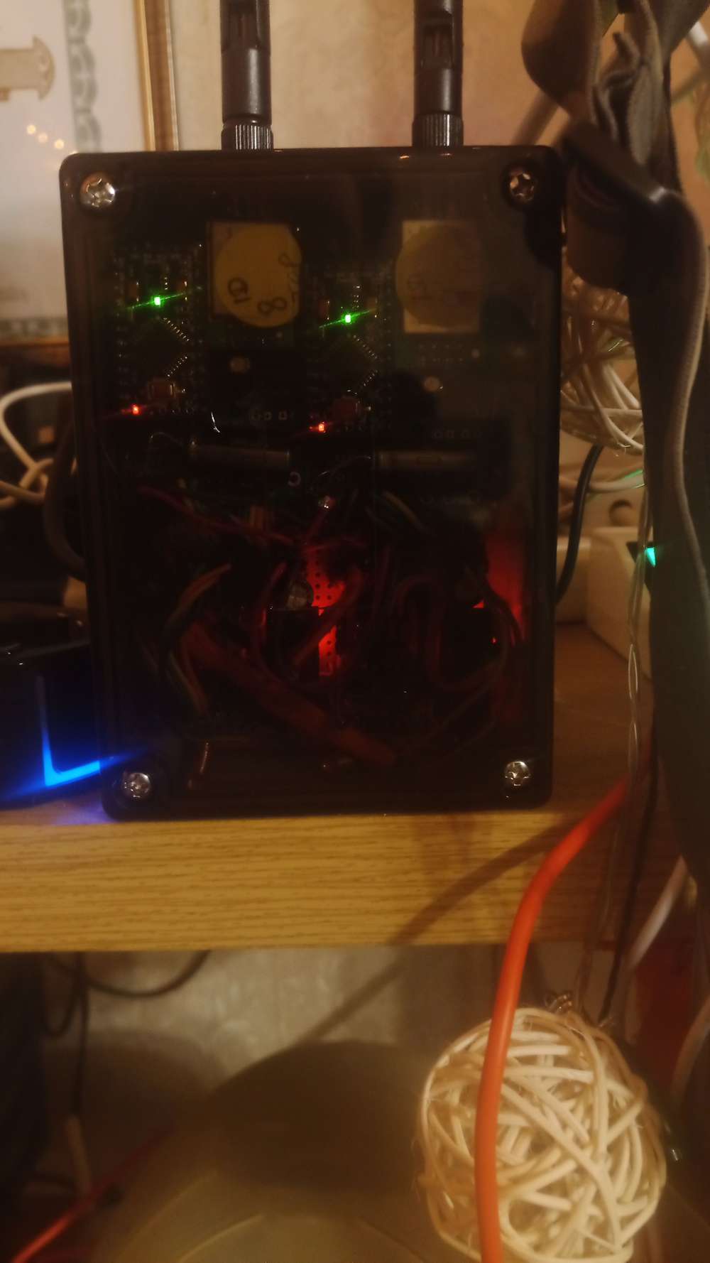
Hello! It looks like you're interested in this conversation, but you don't have an account yet.
Getting fed up of having to scroll through the same posts each visit? When you register for an account, you'll always come back to exactly where you were before, and choose to be notified of new replies (either via email, or push notification). You'll also be able to save bookmarks and upvote posts to show your appreciation to other community members.
With your input, this post could be even better 💗
Register Login