
Help me build a 6-light-sensor & 2 ch relay node.
-
Hi!
I am trying to build a 6-light-sensor & 2 ch relay node to control my old dehumidifier. When I disassembled it, I found 2 switches (power & mode) and 6 leds which can be used to control and report status. Also it has 5v output.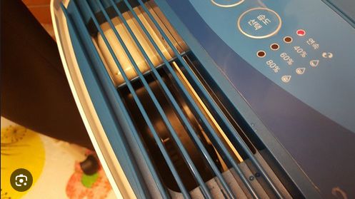
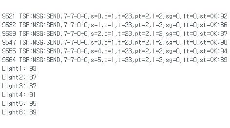
Below is the sketch I came up with. It is showing the light sensor values as below but can't see 2ch relay switches. Am I missing something?
// Enable debug prints
#define MY_DEBUG
// Enable and select radio type attached
#define MY_RADIO_RF24
//#define MY_RADIO_RFM69
//#define MY_RS485
#define MY_NODE_ID 7
#define RELAY_PIN 3 // Arduino Digital I/O pin number for power relay (connected to D3)
#define RELAY_PIN 4 // Arduino Digital I/O pin number for mode relay (connected to D4)
#define NUMBER_OF_RELAYS 2 // Total number of attached relays (2 in this case)
#define RELAY_ON 1 // GPIO value to write to turn on attached relay
#define RELAY_OFF 0 // GPIO value to write to turn off attached relay#define CHILD_ID_LIGHT_1 0
#define CHILD_ID_LIGHT_2 1
#define CHILD_ID_LIGHT_3 2
#define CHILD_ID_LIGHT_4 3
#define CHILD_ID_LIGHT_5 4
#define CHILD_ID_LIGHT_6 5#include <SPI.h>
#include <MySensors.h>#define LIGHT_SENSOR_1_ANALOG_PIN A0
#define LIGHT_SENSOR_2_ANALOG_PIN A1
#define LIGHT_SENSOR_3_ANALOG_PIN A2
#define LIGHT_SENSOR_4_ANALOG_PIN A3
#define LIGHT_SENSOR_5_ANALOG_PIN A4
#define LIGHT_SENSOR_6_ANALOG_PIN A5MyMessage msgLight1(CHILD_ID_LIGHT_1, V_LIGHT_LEVEL);
MyMessage msgLight2(CHILD_ID_LIGHT_2, V_LIGHT_LEVEL);
MyMessage msgLight3(CHILD_ID_LIGHT_3, V_LIGHT_LEVEL);
MyMessage msgLight4(CHILD_ID_LIGHT_4, V_LIGHT_LEVEL);
MyMessage msgLight5(CHILD_ID_LIGHT_5, V_LIGHT_LEVEL);
MyMessage msgLight6(CHILD_ID_LIGHT_6, V_LIGHT_LEVEL);void before()
{
for (int sensor=1, pin=RELAY_PIN; sensor<=NUMBER_OF_RELAYS; sensor++, pin++) {
// Then set relay pins in output mode
pinMode(pin, OUTPUT);
// Set relay to last known state (using eeprom storage)
digitalWrite(pin, loadState(sensor)?RELAY_ON:RELAY_OFF);
}
}void presentation() {
// Send the presentation to the controller
sendSketchInfo("Dehumidifier Controller", "1.0");
present(CHILD_ID_LIGHT_1, S_LIGHT_LEVEL);
present(CHILD_ID_LIGHT_2, S_LIGHT_LEVEL);
present(CHILD_ID_LIGHT_3, S_LIGHT_LEVEL);
present(CHILD_ID_LIGHT_4, S_LIGHT_LEVEL);
present(CHILD_ID_LIGHT_5, S_LIGHT_LEVEL);
present(CHILD_ID_LIGHT_6, S_LIGHT_LEVEL);
for (int sensor=1, pin=RELAY_PIN; sensor<=NUMBER_OF_RELAYS; sensor++, pin++) {
// Register all sensors to gw (they will be created as child devices)
present(sensor, S_BINARY);
}
}void setup() {
// Setup code here if needed
}void loop() {
// Check light levels
int lightLevel1 = analogRead(LIGHT_SENSOR_1_ANALOG_PIN);
int lightLevel2 = analogRead(LIGHT_SENSOR_2_ANALOG_PIN);
int lightLevel3 = analogRead(LIGHT_SENSOR_3_ANALOG_PIN);
int lightLevel4 = analogRead(LIGHT_SENSOR_4_ANALOG_PIN);
int lightLevel5 = analogRead(LIGHT_SENSOR_5_ANALOG_PIN);
int lightLevel6 = analogRead(LIGHT_SENSOR_6_ANALOG_PIN);// Invert the light sensor values: Map the range 0 to 1023 to 100 to 0
lightLevel1 = map(lightLevel1, 0, 1023, 100, 0);
lightLevel2 = map(lightLevel2, 0, 1023, 100, 0);
lightLevel3 = map(lightLevel3, 0, 1023, 100, 0);
lightLevel4 = map(lightLevel4, 0, 1023, 100, 0);
lightLevel5 = map(lightLevel5, 0, 1023, 100, 0);
lightLevel6 = map(lightLevel6, 0, 1023, 100, 0);Serial.print("Light1: ");
Serial.println(lightLevel1);
Serial.print("Light2: ");
Serial.println(lightLevel2);
Serial.print("Light3: ");
Serial.println(lightLevel3);
Serial.print("Light4: ");
Serial.println(lightLevel4);
Serial.print("Light5: ");
Serial.println(lightLevel5);
Serial.print("Light6: ");
Serial.println(lightLevel6);send(msgLight1.set(lightLevel1));
send(msgLight2.set(lightLevel2));
send(msgLight3.set(lightLevel3));
send(msgLight4.set(lightLevel4));
send(msgLight5.set(lightLevel5));
send(msgLight6.set(lightLevel6));// Add any other code for the loop here
delay(1000); // Adjust the delay as needed to control the update rate of the light sensor values
}void receive(const MyMessage &message)
{
// We only expect one type of message from controller. But we better check anyway.
if (message.getType()==V_STATUS) {
// Change relay state
digitalWrite(message.getSensor()-1+RELAY_PIN, message.getBool()?RELAY_ON:RELAY_OFF);
// Store state in eeprom
saveState(message.getSensor(), message.getBool());
// Write some debug info
Serial.print("Incoming change for sensor:");
Serial.print(message.getSensor());
Serial.print(", New status: ");
Serial.println(message.getBool());
}
} -
Hi @airmedic79
I see several problems in your code. Here, you redefine RELAY_PIN:#define RELAY_PIN 3 // Arduino Digital I/O pin number for power relay (connected to D3) #define RELAY_PIN 4 // Arduino Digital I/O pin number for mode relay (connected to D4)Its both times
RELAY_PIN, the same name for the define, so you will end up withRELAY_PINequals 4. This should yield a warning.You never present the binary sensors, because in this line:
for (int sensor=1, pin=RELAY_PIN; sensor<=NUMBER_OF_RELAYS; sensor++, pin++) {RELAY_PINis 4, andNUMBER_OF_RELAYSis 2, so the for loop is never executed.
Also, I think you got a problem with your sensor IDs, i think id 2 and 4 are doubled.Regards, Edi
-
Hi!
I am trying to build a 6-light-sensor & 2 ch relay node to control my old dehumidifier. When I disassembled it, I found 2 switches (power & mode) and 6 leds which can be used to control and report status. Also it has 5v output.Below is the sketch I came up with. It is showing the light sensor values as below but can't see 2ch relay switches. Am I missing something?
// Enable debug prints
#define MY_DEBUG
// Enable and select radio type attached
#define MY_RADIO_RF24
//#define MY_RADIO_RFM69
//#define MY_RS485
#define MY_NODE_ID 7
#define RELAY_PIN 3 // Arduino Digital I/O pin number for power relay (connected to D3)
#define RELAY_PIN 4 // Arduino Digital I/O pin number for mode relay (connected to D4)
#define NUMBER_OF_RELAYS 2 // Total number of attached relays (2 in this case)
#define RELAY_ON 1 // GPIO value to write to turn on attached relay
#define RELAY_OFF 0 // GPIO value to write to turn off attached relay#define CHILD_ID_LIGHT_1 0
#define CHILD_ID_LIGHT_2 1
#define CHILD_ID_LIGHT_3 2
#define CHILD_ID_LIGHT_4 3
#define CHILD_ID_LIGHT_5 4
#define CHILD_ID_LIGHT_6 5#include <SPI.h>
#include <MySensors.h>#define LIGHT_SENSOR_1_ANALOG_PIN A0
#define LIGHT_SENSOR_2_ANALOG_PIN A1
#define LIGHT_SENSOR_3_ANALOG_PIN A2
#define LIGHT_SENSOR_4_ANALOG_PIN A3
#define LIGHT_SENSOR_5_ANALOG_PIN A4
#define LIGHT_SENSOR_6_ANALOG_PIN A5MyMessage msgLight1(CHILD_ID_LIGHT_1, V_LIGHT_LEVEL);
MyMessage msgLight2(CHILD_ID_LIGHT_2, V_LIGHT_LEVEL);
MyMessage msgLight3(CHILD_ID_LIGHT_3, V_LIGHT_LEVEL);
MyMessage msgLight4(CHILD_ID_LIGHT_4, V_LIGHT_LEVEL);
MyMessage msgLight5(CHILD_ID_LIGHT_5, V_LIGHT_LEVEL);
MyMessage msgLight6(CHILD_ID_LIGHT_6, V_LIGHT_LEVEL);void before()
{
for (int sensor=1, pin=RELAY_PIN; sensor<=NUMBER_OF_RELAYS; sensor++, pin++) {
// Then set relay pins in output mode
pinMode(pin, OUTPUT);
// Set relay to last known state (using eeprom storage)
digitalWrite(pin, loadState(sensor)?RELAY_ON:RELAY_OFF);
}
}void presentation() {
// Send the presentation to the controller
sendSketchInfo("Dehumidifier Controller", "1.0");
present(CHILD_ID_LIGHT_1, S_LIGHT_LEVEL);
present(CHILD_ID_LIGHT_2, S_LIGHT_LEVEL);
present(CHILD_ID_LIGHT_3, S_LIGHT_LEVEL);
present(CHILD_ID_LIGHT_4, S_LIGHT_LEVEL);
present(CHILD_ID_LIGHT_5, S_LIGHT_LEVEL);
present(CHILD_ID_LIGHT_6, S_LIGHT_LEVEL);
for (int sensor=1, pin=RELAY_PIN; sensor<=NUMBER_OF_RELAYS; sensor++, pin++) {
// Register all sensors to gw (they will be created as child devices)
present(sensor, S_BINARY);
}
}void setup() {
// Setup code here if needed
}void loop() {
// Check light levels
int lightLevel1 = analogRead(LIGHT_SENSOR_1_ANALOG_PIN);
int lightLevel2 = analogRead(LIGHT_SENSOR_2_ANALOG_PIN);
int lightLevel3 = analogRead(LIGHT_SENSOR_3_ANALOG_PIN);
int lightLevel4 = analogRead(LIGHT_SENSOR_4_ANALOG_PIN);
int lightLevel5 = analogRead(LIGHT_SENSOR_5_ANALOG_PIN);
int lightLevel6 = analogRead(LIGHT_SENSOR_6_ANALOG_PIN);// Invert the light sensor values: Map the range 0 to 1023 to 100 to 0
lightLevel1 = map(lightLevel1, 0, 1023, 100, 0);
lightLevel2 = map(lightLevel2, 0, 1023, 100, 0);
lightLevel3 = map(lightLevel3, 0, 1023, 100, 0);
lightLevel4 = map(lightLevel4, 0, 1023, 100, 0);
lightLevel5 = map(lightLevel5, 0, 1023, 100, 0);
lightLevel6 = map(lightLevel6, 0, 1023, 100, 0);Serial.print("Light1: ");
Serial.println(lightLevel1);
Serial.print("Light2: ");
Serial.println(lightLevel2);
Serial.print("Light3: ");
Serial.println(lightLevel3);
Serial.print("Light4: ");
Serial.println(lightLevel4);
Serial.print("Light5: ");
Serial.println(lightLevel5);
Serial.print("Light6: ");
Serial.println(lightLevel6);send(msgLight1.set(lightLevel1));
send(msgLight2.set(lightLevel2));
send(msgLight3.set(lightLevel3));
send(msgLight4.set(lightLevel4));
send(msgLight5.set(lightLevel5));
send(msgLight6.set(lightLevel6));// Add any other code for the loop here
delay(1000); // Adjust the delay as needed to control the update rate of the light sensor values
}void receive(const MyMessage &message)
{
// We only expect one type of message from controller. But we better check anyway.
if (message.getType()==V_STATUS) {
// Change relay state
digitalWrite(message.getSensor()-1+RELAY_PIN, message.getBool()?RELAY_ON:RELAY_OFF);
// Store state in eeprom
saveState(message.getSensor(), message.getBool());
// Write some debug info
Serial.print("Incoming change for sensor:");
Serial.print(message.getSensor());
Serial.print(", New status: ");
Serial.println(message.getBool());
}
}Only if you send a correct message from the controller to the node
the receive function is called. I don't see a receive in your log.I think in your case the receive-function is not called (or called with a wrong message type or node id). Put a
serial.print("receive() is called with type "); serial.println(message.getType());on top of the receive function to see if the receive function is called and which type is handed over..
Hello! It looks like you're interested in this conversation, but you don't have an account yet.
Getting fed up of having to scroll through the same posts each visit? When you register for an account, you'll always come back to exactly where you were before, and choose to be notified of new replies (either via email, or push notification). You'll also be able to save bookmarks and upvote posts to show your appreciation to other community members.
With your input, this post could be even better 💗
Register Login