Help me build a 6-light-sensor & 2 ch relay node.
-
Hi!
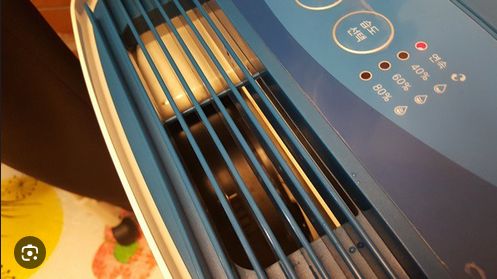
I am trying to build a 6-light-sensor & 2 ch relay node to control my old dehumidifier. When I disassembled it, I found 2 switches (power & mode) and 6 leds which can be used to control and report status. Also it has 5v output.
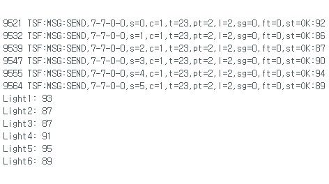
Below is the sketch I came up with. It is showing the light sensor values as below but can't see 2ch relay switches. Am I missing something?

// Enable debug prints
#define MY_DEBUG
// Enable and select radio type attached
#define MY_RADIO_RF24
//#define MY_RADIO_RFM69
//#define MY_RS485
#define MY_NODE_ID 7
#define RELAY_PIN 3 // Arduino Digital I/O pin number for power relay (connected to D3)
#define RELAY_PIN 4 // Arduino Digital I/O pin number for mode relay (connected to D4)
#define NUMBER_OF_RELAYS 2 // Total number of attached relays (2 in this case)
#define RELAY_ON 1 // GPIO value to write to turn on attached relay
#define RELAY_OFF 0 // GPIO value to write to turn off attached relay#define CHILD_ID_LIGHT_1 0
#define CHILD_ID_LIGHT_2 1
#define CHILD_ID_LIGHT_3 2
#define CHILD_ID_LIGHT_4 3
#define CHILD_ID_LIGHT_5 4
#define CHILD_ID_LIGHT_6 5#include <SPI.h>
#include <MySensors.h>#define LIGHT_SENSOR_1_ANALOG_PIN A0
#define LIGHT_SENSOR_2_ANALOG_PIN A1
#define LIGHT_SENSOR_3_ANALOG_PIN A2
#define LIGHT_SENSOR_4_ANALOG_PIN A3
#define LIGHT_SENSOR_5_ANALOG_PIN A4
#define LIGHT_SENSOR_6_ANALOG_PIN A5MyMessage msgLight1(CHILD_ID_LIGHT_1, V_LIGHT_LEVEL);
MyMessage msgLight2(CHILD_ID_LIGHT_2, V_LIGHT_LEVEL);
MyMessage msgLight3(CHILD_ID_LIGHT_3, V_LIGHT_LEVEL);
MyMessage msgLight4(CHILD_ID_LIGHT_4, V_LIGHT_LEVEL);
MyMessage msgLight5(CHILD_ID_LIGHT_5, V_LIGHT_LEVEL);
MyMessage msgLight6(CHILD_ID_LIGHT_6, V_LIGHT_LEVEL);void before()
{
for (int sensor=1, pin=RELAY_PIN; sensor<=NUMBER_OF_RELAYS; sensor++, pin++) {
// Then set relay pins in output mode
pinMode(pin, OUTPUT);
// Set relay to last known state (using eeprom storage)
digitalWrite(pin, loadState(sensor)?RELAY_ON:RELAY_OFF);
}
}void presentation() {
// Send the presentation to the controller
sendSketchInfo("Dehumidifier Controller", "1.0");
present(CHILD_ID_LIGHT_1, S_LIGHT_LEVEL);
present(CHILD_ID_LIGHT_2, S_LIGHT_LEVEL);
present(CHILD_ID_LIGHT_3, S_LIGHT_LEVEL);
present(CHILD_ID_LIGHT_4, S_LIGHT_LEVEL);
present(CHILD_ID_LIGHT_5, S_LIGHT_LEVEL);
present(CHILD_ID_LIGHT_6, S_LIGHT_LEVEL);
for (int sensor=1, pin=RELAY_PIN; sensor<=NUMBER_OF_RELAYS; sensor++, pin++) {
// Register all sensors to gw (they will be created as child devices)
present(sensor, S_BINARY);
}
}void setup() {
// Setup code here if needed
}void loop() {
// Check light levels
int lightLevel1 = analogRead(LIGHT_SENSOR_1_ANALOG_PIN);
int lightLevel2 = analogRead(LIGHT_SENSOR_2_ANALOG_PIN);
int lightLevel3 = analogRead(LIGHT_SENSOR_3_ANALOG_PIN);
int lightLevel4 = analogRead(LIGHT_SENSOR_4_ANALOG_PIN);
int lightLevel5 = analogRead(LIGHT_SENSOR_5_ANALOG_PIN);
int lightLevel6 = analogRead(LIGHT_SENSOR_6_ANALOG_PIN);// Invert the light sensor values: Map the range 0 to 1023 to 100 to 0
lightLevel1 = map(lightLevel1, 0, 1023, 100, 0);
lightLevel2 = map(lightLevel2, 0, 1023, 100, 0);
lightLevel3 = map(lightLevel3, 0, 1023, 100, 0);
lightLevel4 = map(lightLevel4, 0, 1023, 100, 0);
lightLevel5 = map(lightLevel5, 0, 1023, 100, 0);
lightLevel6 = map(lightLevel6, 0, 1023, 100, 0);Serial.print("Light1: ");
Serial.println(lightLevel1);
Serial.print("Light2: ");
Serial.println(lightLevel2);
Serial.print("Light3: ");
Serial.println(lightLevel3);
Serial.print("Light4: ");
Serial.println(lightLevel4);
Serial.print("Light5: ");
Serial.println(lightLevel5);
Serial.print("Light6: ");
Serial.println(lightLevel6);send(msgLight1.set(lightLevel1));
send(msgLight2.set(lightLevel2));
send(msgLight3.set(lightLevel3));
send(msgLight4.set(lightLevel4));
send(msgLight5.set(lightLevel5));
send(msgLight6.set(lightLevel6));// Add any other code for the loop here
delay(1000); // Adjust the delay as needed to control the update rate of the light sensor values
}void receive(const MyMessage &message)
{
// We only expect one type of message from controller. But we better check anyway.
if (message.getType()==V_STATUS) {
// Change relay state
digitalWrite(message.getSensor()-1+RELAY_PIN, message.getBool()?RELAY_ON:RELAY_OFF);
// Store state in eeprom
saveState(message.getSensor(), message.getBool());
// Write some debug info
Serial.print("Incoming change for sensor:");
Serial.print(message.getSensor());
Serial.print(", New status: ");
Serial.println(message.getBool());
}
} -
Hi @airmedic79
I see several problems in your code. Here, you redefine RELAY_PIN:#define RELAY_PIN 3 // Arduino Digital I/O pin number for power relay (connected to D3) #define RELAY_PIN 4 // Arduino Digital I/O pin number for mode relay (connected to D4)Its both times
RELAY_PIN, the same name for the define, so you will end up withRELAY_PINequals 4. This should yield a warning.You never present the binary sensors, because in this line:
for (int sensor=1, pin=RELAY_PIN; sensor<=NUMBER_OF_RELAYS; sensor++, pin++) {RELAY_PINis 4, andNUMBER_OF_RELAYSis 2, so the for loop is never executed.
Also, I think you got a problem with your sensor IDs, i think id 2 and 4 are doubled.Regards, Edi
-
Hi!
I am trying to build a 6-light-sensor & 2 ch relay node to control my old dehumidifier. When I disassembled it, I found 2 switches (power & mode) and 6 leds which can be used to control and report status. Also it has 5v output.
Below is the sketch I came up with. It is showing the light sensor values as below but can't see 2ch relay switches. Am I missing something?

// Enable debug prints
#define MY_DEBUG
// Enable and select radio type attached
#define MY_RADIO_RF24
//#define MY_RADIO_RFM69
//#define MY_RS485
#define MY_NODE_ID 7
#define RELAY_PIN 3 // Arduino Digital I/O pin number for power relay (connected to D3)
#define RELAY_PIN 4 // Arduino Digital I/O pin number for mode relay (connected to D4)
#define NUMBER_OF_RELAYS 2 // Total number of attached relays (2 in this case)
#define RELAY_ON 1 // GPIO value to write to turn on attached relay
#define RELAY_OFF 0 // GPIO value to write to turn off attached relay#define CHILD_ID_LIGHT_1 0
#define CHILD_ID_LIGHT_2 1
#define CHILD_ID_LIGHT_3 2
#define CHILD_ID_LIGHT_4 3
#define CHILD_ID_LIGHT_5 4
#define CHILD_ID_LIGHT_6 5#include <SPI.h>
#include <MySensors.h>#define LIGHT_SENSOR_1_ANALOG_PIN A0
#define LIGHT_SENSOR_2_ANALOG_PIN A1
#define LIGHT_SENSOR_3_ANALOG_PIN A2
#define LIGHT_SENSOR_4_ANALOG_PIN A3
#define LIGHT_SENSOR_5_ANALOG_PIN A4
#define LIGHT_SENSOR_6_ANALOG_PIN A5MyMessage msgLight1(CHILD_ID_LIGHT_1, V_LIGHT_LEVEL);
MyMessage msgLight2(CHILD_ID_LIGHT_2, V_LIGHT_LEVEL);
MyMessage msgLight3(CHILD_ID_LIGHT_3, V_LIGHT_LEVEL);
MyMessage msgLight4(CHILD_ID_LIGHT_4, V_LIGHT_LEVEL);
MyMessage msgLight5(CHILD_ID_LIGHT_5, V_LIGHT_LEVEL);
MyMessage msgLight6(CHILD_ID_LIGHT_6, V_LIGHT_LEVEL);void before()
{
for (int sensor=1, pin=RELAY_PIN; sensor<=NUMBER_OF_RELAYS; sensor++, pin++) {
// Then set relay pins in output mode
pinMode(pin, OUTPUT);
// Set relay to last known state (using eeprom storage)
digitalWrite(pin, loadState(sensor)?RELAY_ON:RELAY_OFF);
}
}void presentation() {
// Send the presentation to the controller
sendSketchInfo("Dehumidifier Controller", "1.0");
present(CHILD_ID_LIGHT_1, S_LIGHT_LEVEL);
present(CHILD_ID_LIGHT_2, S_LIGHT_LEVEL);
present(CHILD_ID_LIGHT_3, S_LIGHT_LEVEL);
present(CHILD_ID_LIGHT_4, S_LIGHT_LEVEL);
present(CHILD_ID_LIGHT_5, S_LIGHT_LEVEL);
present(CHILD_ID_LIGHT_6, S_LIGHT_LEVEL);
for (int sensor=1, pin=RELAY_PIN; sensor<=NUMBER_OF_RELAYS; sensor++, pin++) {
// Register all sensors to gw (they will be created as child devices)
present(sensor, S_BINARY);
}
}void setup() {
// Setup code here if needed
}void loop() {
// Check light levels
int lightLevel1 = analogRead(LIGHT_SENSOR_1_ANALOG_PIN);
int lightLevel2 = analogRead(LIGHT_SENSOR_2_ANALOG_PIN);
int lightLevel3 = analogRead(LIGHT_SENSOR_3_ANALOG_PIN);
int lightLevel4 = analogRead(LIGHT_SENSOR_4_ANALOG_PIN);
int lightLevel5 = analogRead(LIGHT_SENSOR_5_ANALOG_PIN);
int lightLevel6 = analogRead(LIGHT_SENSOR_6_ANALOG_PIN);// Invert the light sensor values: Map the range 0 to 1023 to 100 to 0
lightLevel1 = map(lightLevel1, 0, 1023, 100, 0);
lightLevel2 = map(lightLevel2, 0, 1023, 100, 0);
lightLevel3 = map(lightLevel3, 0, 1023, 100, 0);
lightLevel4 = map(lightLevel4, 0, 1023, 100, 0);
lightLevel5 = map(lightLevel5, 0, 1023, 100, 0);
lightLevel6 = map(lightLevel6, 0, 1023, 100, 0);Serial.print("Light1: ");
Serial.println(lightLevel1);
Serial.print("Light2: ");
Serial.println(lightLevel2);
Serial.print("Light3: ");
Serial.println(lightLevel3);
Serial.print("Light4: ");
Serial.println(lightLevel4);
Serial.print("Light5: ");
Serial.println(lightLevel5);
Serial.print("Light6: ");
Serial.println(lightLevel6);send(msgLight1.set(lightLevel1));
send(msgLight2.set(lightLevel2));
send(msgLight3.set(lightLevel3));
send(msgLight4.set(lightLevel4));
send(msgLight5.set(lightLevel5));
send(msgLight6.set(lightLevel6));// Add any other code for the loop here
delay(1000); // Adjust the delay as needed to control the update rate of the light sensor values
}void receive(const MyMessage &message)
{
// We only expect one type of message from controller. But we better check anyway.
if (message.getType()==V_STATUS) {
// Change relay state
digitalWrite(message.getSensor()-1+RELAY_PIN, message.getBool()?RELAY_ON:RELAY_OFF);
// Store state in eeprom
saveState(message.getSensor(), message.getBool());
// Write some debug info
Serial.print("Incoming change for sensor:");
Serial.print(message.getSensor());
Serial.print(", New status: ");
Serial.println(message.getBool());
}
}Only if you send a correct message from the controller to the node
the receive function is called. I don't see a receive in your log.I think in your case the receive-function is not called (or called with a wrong message type or node id). Put a
serial.print("receive() is called with type "); serial.println(message.getType());on top of the receive function to see if the receive function is called and which type is handed over..
