Home Assistant Serial Gateway with Supply rail monitoring
-
I have built a HA rack mounted controller which consists of a mains psu which is connected to a 'psu pcb' which provides +5v +12v and 13.2v bat output. If the mains fails the battery will maintain all rails for about 2 hours. The 5v rail supplies the Raspberry Pi5 running HA and an arduino for the Mysensors serial gateway. I have built a similar system a few years ago with a domoticz controller and was able to monitor the supply rails using the A/D inputs on the gateway.
Problem is that the sketch used in Domoticz doesn't work with HA so i have re-written it following the advice from the HA mysensors page https://www.home-assistant.io/integrations/mysensors/
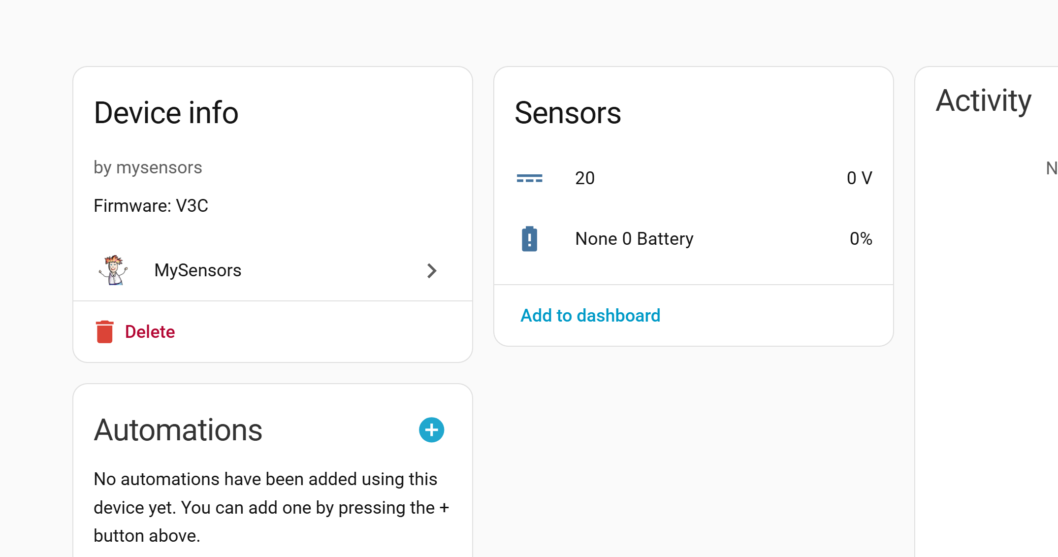
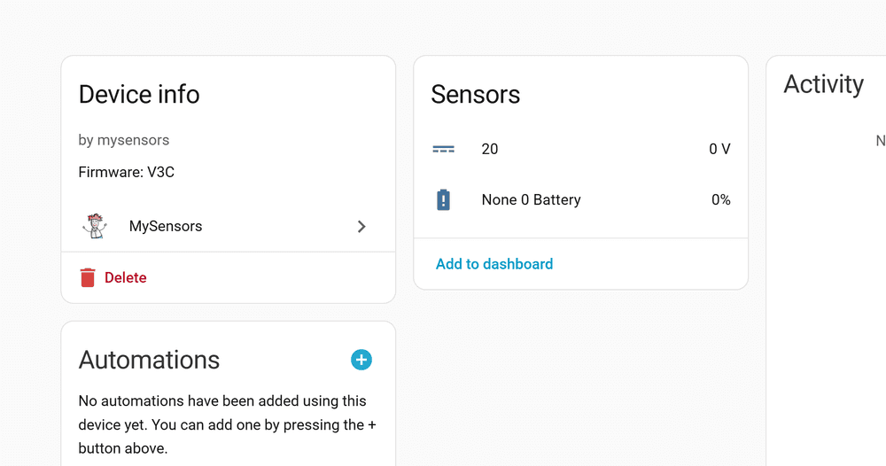
I have written this latest sketch to display 1 supply rail (not defined) and it appears in the Mysensors integration in HA only problem it is 0.00. see pic ('20' is the child ID)
I am using an Arduino Mega for the gateway which works fine and hope to add an LCD display later (the earlier domoticz version also has one)
Can someone clever see where i have gone wrong?/** * 20/01/2026 USE 2.3.1 ,Shows voltage in HA but no value, maths may be wrong. * * * * - NRF24 Radio fed from 5v PSU sub board D9-D13 * - 3 status LED's D4,D5,D6 * - 5 Analogue inputs from PSU board A1-A5 * * NRF Connections * CE 49 * CSN/CS 53 * SCK 52 * MOSI 51 * MISO 50 * * Works on lots of Mysensors versions * Currently working on 2.3.1 * * The MySensors Arduino library handles the wireless radio link and protocol * Copyright (C) 2013-2015 Sensnology AB * Full contributor list: https://github.com/mysensors/Arduino/graphs/contributors * * Documentation: http://www.mysensors.org * Support Forum: http://forum.mysensors.org * ******************************* * * DESCRIPTION * The ArduinoGateway prints data received from sensors on the serial link. * The gateway accepts input on seral which will be sent out on radio network. * * The GW code is designed for Arduino Nano 328p / 16MHz * * Wire connections (OPTIONAL): * - Inclusion button should be connected between digital pin 3 and GND * - RX/TX/ERR leds need to be connected between +5V (anode) and digital pin 6/5/4 with resistor 270-330R in a series * * LEDs (OPTIONAL): * - To use the feature, uncomment any of the MY_DEFAULT_xx_LED_PINs * - RX (green) - blink fast on radio message recieved. In inclusion mode will blink fast only on presentation recieved * - TX (yellow) - blink fast on radio message transmitted. In inclusion mode will blink slowly * - ERR (red) - fast blink on error during transmission error or recieve crc error * */ // Enable debug prints to serial monitor #define MY_DEBUG // Enable and select radio type attached #define MY_RADIO_NRF24 #define MY_RF24_CE_PIN 49 #define MY_RF24_CS_PIN 53 // Set LOW transmit power level as default, if you have an amplified NRF-module and // power your radio separately with a good regulator you can turn up PA level. #define MY_RF24_PA_LEVEL RF24_PA_MIN //settings are MIN, LOW, HIGH, MAX // Enable serial gateway #define MY_GATEWAY_SERIAL // Define a lower baud rate for Arduino's running on 8 MHz (Arduino Pro Mini 3.3V & SenseBender) #if F_CPU == 8000000L #define MY_BAUD_RATE 38400 #endif // Enable inclusion mode #define MY_INCLUSION_MODE_FEATURE // Enable Inclusion mode button on gateway //#define MY_INCLUSION_BUTTON_FEATURE // Inverses behavior of inclusion button (if using external pullup) //#define MY_INCLUSION_BUTTON_EXTERNAL_PULLUP // Set inclusion mode duration (in seconds) #define MY_INCLUSION_MODE_DURATION 60 // Digital pin used for inclusion mode button //#define MY_INCLUSION_MODE_BUTTON_PIN 3 // Set blinking period #define MY_DEFAULT_LED_BLINK_PERIOD 300 // Inverses the behavior of leds #define MY_WITH_LEDS_BLINKING_INVERSE // Flash leds on rx/tx/err // Uncomment to override default HW configurations #define MY_DEFAULT_ERR_LED_PIN 4 // Error led pin RED #define MY_DEFAULT_RX_LED_PIN 5 // Receive led pin GREEN #define MY_DEFAULT_TX_LED_PIN 6 // Transmit LED pin YELLOW #include <MySensors.h> #define CHILD_ID 20 #define BATTERY_SENSE_PIN A4 // 13.4V DC/DC unsigned long SLEEP_TIME = 2000; // sleep time between reads (seconds * 1000 milliseconds) float lastVolt; float batteryV; //boolean metric = true; MyMessage msgVolt(CHILD_ID, V_VOLTAGE); void setup() {} // 13.4V PSU void measureBattery() { // VR1 = 10K Pot int sensorValue = analogRead(BATTERY_SENSE_PIN); float batteryV = sensorValue * (4 / 1023) * 2; if(lastVolt != batteryV) { lastVolt = batteryV; } } void presentation() { sendSketchInfo("MEGA GW", "V3C"); present(CHILD_ID, S_MULTIMETER); present(CHILD_ID, V_VOLTAGE); } void loop() { measureBattery(); //Serial.print("PSU: "); // Serial.println(batteryV); request(CHILD_ID, V_VOLTAGE); send(msgVolt.set(batteryV, 2)); sleep(SLEEP_TIME); //sleep a bit }4;2;1;0;20;1
0;20;2;0;38;
0;20;1;0;38;0.00
0;255;3;0;9;1756043 MCO:SLP:MS=2000,SMS=0,I1=255,M1=255,I2=255,M2=255
0;255;3;0;9;1756050 !MCO:SLP:REP
0;20;2;0;38;
0;20;1;0;38;0.00
0;255;3;0;9;1758054 MCO:SLP:MS=2000,SMS=0,I1=255,M1=255,I2=255,M2=255
0;255;3;0;9;1758061 !MCO:SLP:REP -
Update. Duh. I see you are getting the voltage to HA (20 0V ). So maybe ignore my original post.
In your presentation function, you present CHILD_ID twice. I think you just want to present it as S_MULTIMETER. Delete the V_VOLTAGE from presentation. Your MyMessage msgVolt declaration tells it that it is a V_VOLTAGE.
Not sure if this is the fix, but it is probably not correct as is. -
That None 0 Battery is the battery percentage from sendBatteryLevel(), which you aren't using in your sketch. You should be seeing an entry for the voltage you are sending besides that one.
Your message output indicates you are sending 0.00 for the voltage. Check the output of float batteryV = sensorValue * (4 / 1023) * 2; with a printf. If it comes out as zero, double check the sensorValue. Also check 4/1023. It would be zero if processed as an int. try 4.0/1023.0 and see if that helps. Even as a float it is a very small number. sensorValue would need to be about 128 for it to register as a 1.
I've had some challenges with floats and ints in the past -- admittedly not an expert. I should actually learn how arduino handles them : )Update: Duh I see it. 20 0V. So ignore what I said about None 0 Battery. You are sending 0V however. See below.
PS. I like HA for all the other stuff it can do besides MySensors, but I sometimes do miss Domoticz. -
If you haven't used it, the log parser is really helpful: https://www.mysensors.org/build/parser
Makes it easy to see you are sending 0.00 for V_VOLTAGE. -
Thanks for the quick response, I have removed the second V_VOLTAGE and added the .0 to the sensorValue line, this did not fix the problem. I took your advice and serial printed the lastVolt, batteryVolt and sensorValue. I need to work out why but the lastVolt reading is correct so i have sent 'send(msgVolt.set(lastVolt, 2)); ' this to the gateway and this now works. Need to think about this a but more. By the way that parsor is really useful i never knew it existed. Thanks for all your suggestions!
-
Good project. Let us know how this works out for you!
Hello! It looks like you're interested in this conversation, but you don't have an account yet.
Getting fed up of having to scroll through the same posts each visit? When you register for an account, you'll always come back to exactly where you were before, and choose to be notified of new replies (either via email, or push notification). You'll also be able to save bookmarks and upvote posts to show your appreciation to other community members.
With your input, this post could be even better 💗
Register Login