IR Blaster (progress)
-
Several people have requested the IR Blaster that I demonstrated in this this Luminara Candle Actuator post but the 1st generation IR Blaster is tedious to build by hand so I decided to develop a purpose-built IR Blaster Actuator. The concept is to collapse everything from the 1st generation IR blaster down to a single PCB that also incorporates all the MySensor's capabilities (e.g. OTA sketch updates and hardware message-signing), add a temperature and humidity sensor (why not?), and a high-luminance, long-range IR Blaster all powered by a standard 5VDC AC power adapter. The IR Blaster can be used to control multiple devices in your home that use a standard infrared remote control (e.g. TV, Receiver, DVR, Air Conditioner, Luminara candles, etc.). Below is an overview, the initial schematic and a rough board layout to give you a sense of the design and size. In discussing with @Hek, if there is enough interest, we will offer this board on ITead Studio so if you are interested, please weigh in and more importantly blast away (pun intended) with critiques or flaws in the features, design, etc.
MySensors Core (derivative work of @tobowmo's Sensebender Micro who deserves a ton of credit and huge thanks for this circuit!)
- ATMEL MCU - ATMEGA 328P / Arduino compatible
- Hardware encryption for message signing - ATSHA204A (thanks to @Anticimex for developing the message signing support)
- Flash for OTA sketch updates - AT25F512C (thanks to @tosa and @tekka for the OTA sketch support)
- Radio - NRF24L01+ socket
- 3.3 VDC on-board LDO voltage regulator to power MySensors MCU & Radio Core
Actuators
- High-Luminance IR Blaster (5 IR LEDs)
- Driven by logic-level MOSFET for maximum current distribution to IR LEDs
- Separate 5.0 VDC on-board LDO voltage regulator to power IR blaster (Isolate MySensors Core from IR current dips)
- 180 degree illumination
Sensors
- IR receiver socket (can be used for IR decoding for sketch customization)
- Temperature and Humidity (Si7021 - same sensor that Thomas Mørch selected for the Sense-Bender Micro)
3 Analog Inputs
- A0, A1, A2 (auxiliary input for other sensors - e.g. PIR, luminance, etc.)
Other
- Rx, Tx, and Err LEDs (credit to @thozza for adding LED support to sensors/actuators)
Power
- list itemStandard 5VDC adapter (regulated on board to 3.3V)
Open questions
- IR LED choice - range versus luminance spread (IR-333-A vs. IR-333-C or hybrid)
- Include an external oscillator/crystal
- Decoupling capacitor value for NRF24L01+
- Include barrel connector to simultaneously drive external IR LED emitters
- Physical learn-mode trigger
(added) Driving 5 IR LEDs at maximum luminance with a single transistor (will breadboard to confirm)(added) Include a 5V power plane
@blacey said:
Open questions
- Driving 5 IR LEDs at maximum luminance with a single transistor (will breadboard to confirm)
- IR LED choice - range versus luminance spread (IR-333-A vs. IR-333-C)
Looks like a great design and I like the suggested name :-)
Since the LEDs are through-hole, you could leave them out and let each user select what they need for their particular situation, Would be great if it could support external emitters or blasters as well connected through a 3.5mm plug. Something like these: http://www.ebay.com/itm/131369608040.
Cheers
Al -
Really Nice! Ive been thinking about a need for one of these recently to control a gas heater with IR remote function!...and I'd also missed your original post too, so looks like ill be ordering some IR candles too!
Happy wife thru gadgets like this also gives us more licence to spend hours tinkering!!!
;-)
-
Just a thought on the software side. ( ive not really thought it through...just chucking the thought out here...)
What if we could add a "learn" button to the "blacey-blaster" - pressing this would put the blaster into "learn" mode, and then the oem remote control button IR code could be then loaded into the eeprom or flash memory.
.....and then somehow the controller would be notified of the IR code index location which could then be programmed into the controller (vera) software...or the OTA sketch updated to create multiple devices and the respective IR codes.
So on a single blaster you would create a child device of
S_LIGHT for the candles, and you would pick IR index of 0 and 1 for OFF/ON
and another child of S_HEATER which might use IR index of ,2,3,4,5 for OFF/ON/HIGH/MID/LOW or whatever functions the heater has...Hope this makes a bit of sense....
-
Thanks for the great feedback! I just revised the original thread post with version 0.2 of the schematic that incorporates the following changes (I hope revising the original post isn't bad forum etiquette):
@tbowmo - ok, I'm sold. I did some research and was able to find some reasonably inexpensive N-Channel MOSFETs that can handle more than 600 mA with comparably fast switching times in a SOT-23 package. I also incorporated a separate 5 VDC rail but added a simplistic 5 VDC LDO voltage regulator the board can take anywhere from 5V to 12 VDC (as I am typing this, I am thinking it should just be a separate 3.3VDC rail given 1.1-1.3 voltage dropout).
Two questions for you
- Do you think I need to incorporate an external oscillator? While there is a dependency between the PWM timers and the clock speed, I think this should work fine with the built-in 8MHz clock
- Any thoughts on a common MySensors Core 3.3 VDC LDO circuit (ICs/de-coupling capacitors, etc.)
@Sparkman - added external LEDs as an open issue given because it requires some design/thought. Any suggestions on a universally acceptable current resistor that would be compatible with a broad set of emitters and or IR repeater blocks? Also, I'm not sure it would be a good idea for roll-your-own LEDs given the dependency between the current limiting resistor and the current limitations for IR LEDs that people might select. If you have a suggestion for good IR LEDs, let me know. I am thinking 3 IR-333-A and 2 IR-333-C given 20/30 respective beam widths. The IR-333-A get great ratings due to their high luminance. I'm still researching more but am open to all suggestions.
@gregl - on the software side, great idea for a learn button but we are running out of pins. I suspect that once most people install the blaster, they will use a separate (more conveniently located) IR receiver to collect the codes and then update them in the blaster using the OTA firmware capability. My blaster is installed on top of one of my surround speakers well out of reach so I don't plan to pull it down just to learn. I added the socket so people could bootstrap by plugging a receiver into the socket but after that, I would suggest connecting it to an UNO or breadboard Arduino for learning.
-
I think it would be good to at least have the footprints for the external oscillator components, You could always decide later on if the oscillator is needed, and leave it as not mounted. It's harder to implement it afterwards, if we do find it to be necessary
And yes, probably do make sense to have some common components (If we are going to use same partner in China for all boards), then we can reuse special components between the different boards.
-
Thanks for the great feedback! I just revised the original thread post with version 0.2 of the schematic that incorporates the following changes (I hope revising the original post isn't bad forum etiquette):
@tbowmo - ok, I'm sold. I did some research and was able to find some reasonably inexpensive N-Channel MOSFETs that can handle more than 600 mA with comparably fast switching times in a SOT-23 package. I also incorporated a separate 5 VDC rail but added a simplistic 5 VDC LDO voltage regulator the board can take anywhere from 5V to 12 VDC (as I am typing this, I am thinking it should just be a separate 3.3VDC rail given 1.1-1.3 voltage dropout).
Two questions for you
- Do you think I need to incorporate an external oscillator? While there is a dependency between the PWM timers and the clock speed, I think this should work fine with the built-in 8MHz clock
- Any thoughts on a common MySensors Core 3.3 VDC LDO circuit (ICs/de-coupling capacitors, etc.)
@Sparkman - added external LEDs as an open issue given because it requires some design/thought. Any suggestions on a universally acceptable current resistor that would be compatible with a broad set of emitters and or IR repeater blocks? Also, I'm not sure it would be a good idea for roll-your-own LEDs given the dependency between the current limiting resistor and the current limitations for IR LEDs that people might select. If you have a suggestion for good IR LEDs, let me know. I am thinking 3 IR-333-A and 2 IR-333-C given 20/30 respective beam widths. The IR-333-A get great ratings due to their high luminance. I'm still researching more but am open to all suggestions.
@gregl - on the software side, great idea for a learn button but we are running out of pins. I suspect that once most people install the blaster, they will use a separate (more conveniently located) IR receiver to collect the codes and then update them in the blaster using the OTA firmware capability. My blaster is installed on top of one of my surround speakers well out of reach so I don't plan to pull it down just to learn. I added the socket so people could bootstrap by plugging a receiver into the socket but after that, I would suggest connecting it to an UNO or breadboard Arduino for learning.
@blacey said:
@Sparkman - added external LEDs as an open issue given because it requires some design/thought. Any suggestions on a universally acceptable current resistor that would be compatible with a broad set of emitters and or IR repeater blocks? Also, I'm not sure it would be a good idea for roll-your-own LEDs given the dependency between the current limiting resistor and the current limitations for IR LEDs that people might select. If you have a suggestion for good IR LEDs, let me know. I am thinking 3 IR-333-A and 2 IR-333-C given 20/30 respective beam widths. The IR-333-A get great ratings due to their high luminance. I'm still researching more but am open to all suggestions.
Thanks for considering it. I have a few different brands of external emitters kicking around so I'll do some measurements with them. From what I have read, a lot of the commercial systems use 470Ω, but they typically run at 12V. As to the on-board LEDs, I think it would be important to select LEDs with a beam width that ensure no dead spots given the way they are placed on the board. What's the approximate placement angle? Looks to be about 20-25 degrees between the LEDs.
Cheers
Al -
I think it would be good to at least have the footprints for the external oscillator components, You could always decide later on if the oscillator is needed, and leave it as not mounted. It's harder to implement it afterwards, if we do find it to be necessary
And yes, probably do make sense to have some common components (If we are going to use same partner in China for all boards), then we can reuse special components between the different boards.
@tbowmo - thanks :+1:
- Oscillator pads - added to v0.3 schematic (done).
- Are you interested in proposing a MySensors common core 3.3VDC regulator circuit? In an ideal world, we would have a single circuit design for power adapters and batteries, when needed, (switching vs. LDO) with enough current output (i.e. ~1A) for circuits that demand it (e.g. parallel IR LEDs). Icing on the cake would be a wide-range of input voltages. For example, when I get back to the multi-channel LED dimmer, it will need to handle 12-24 VDC as input. Are you game?
@Sparkman - thanks :+1:
-
Thanks for offering to work through the design details for the external emitters. We will need to define constraints for the external emitter performance characteristics IF & VF. If possible, it would be great if we can support IR blocks as well from a single barrel connector.
-
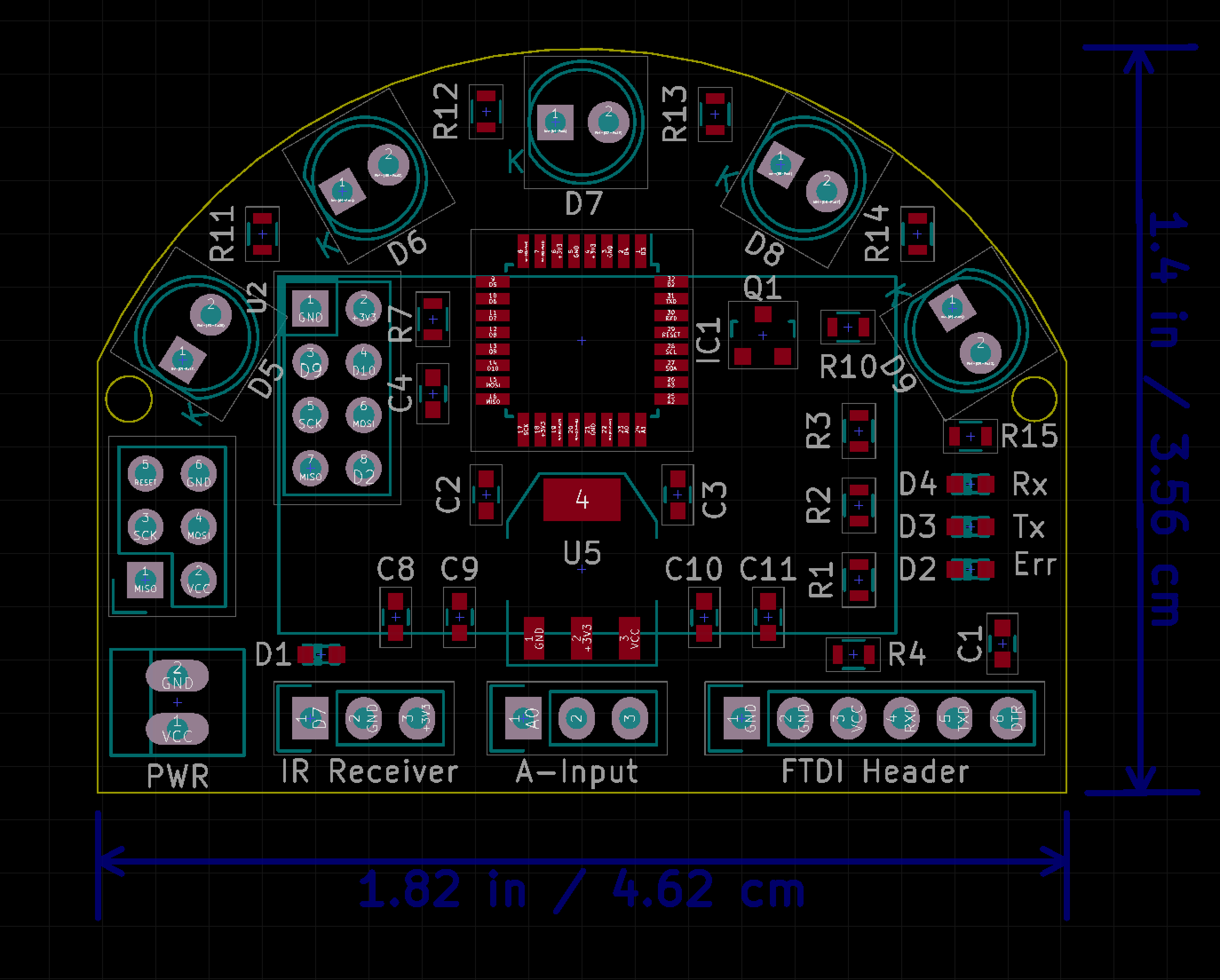
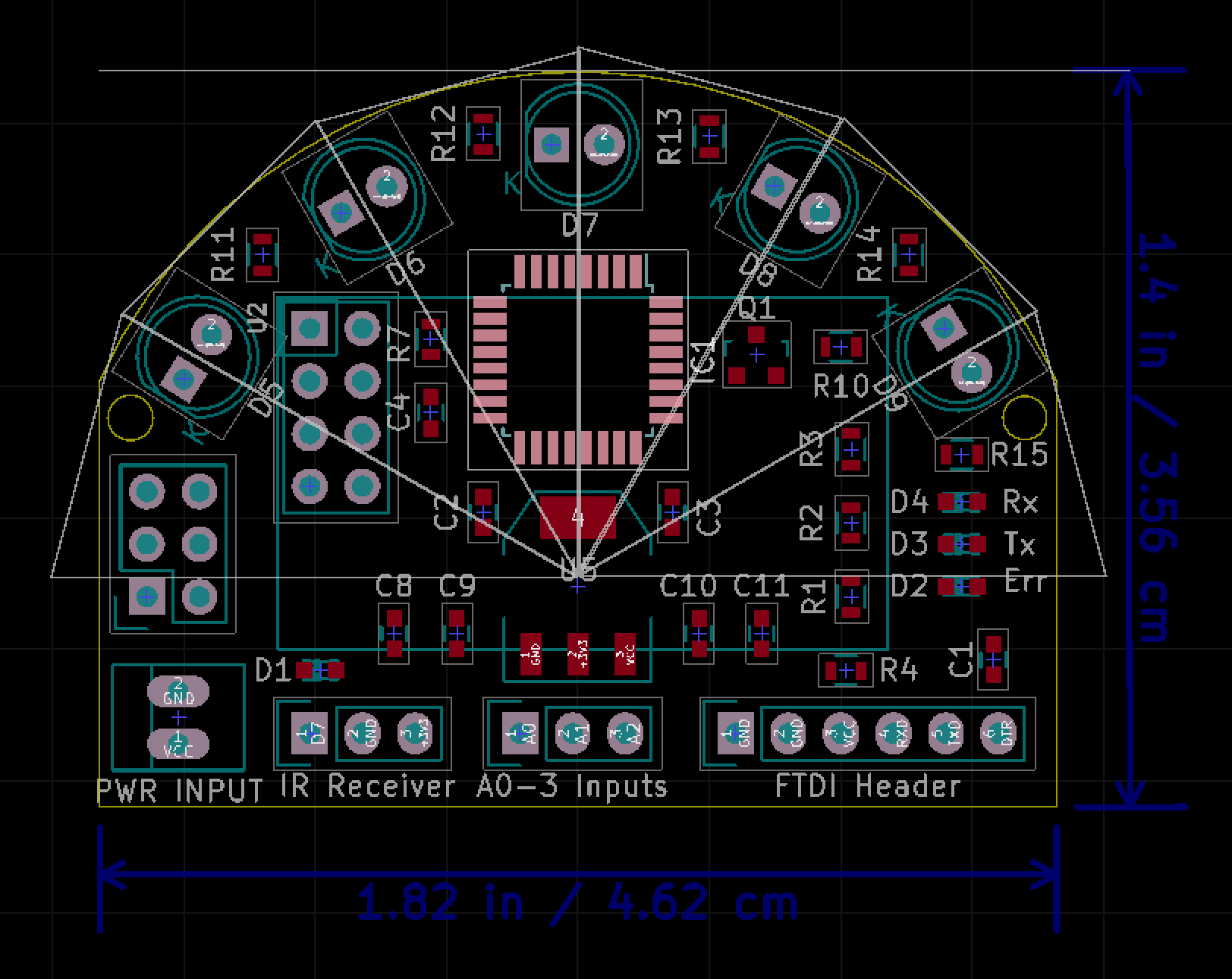
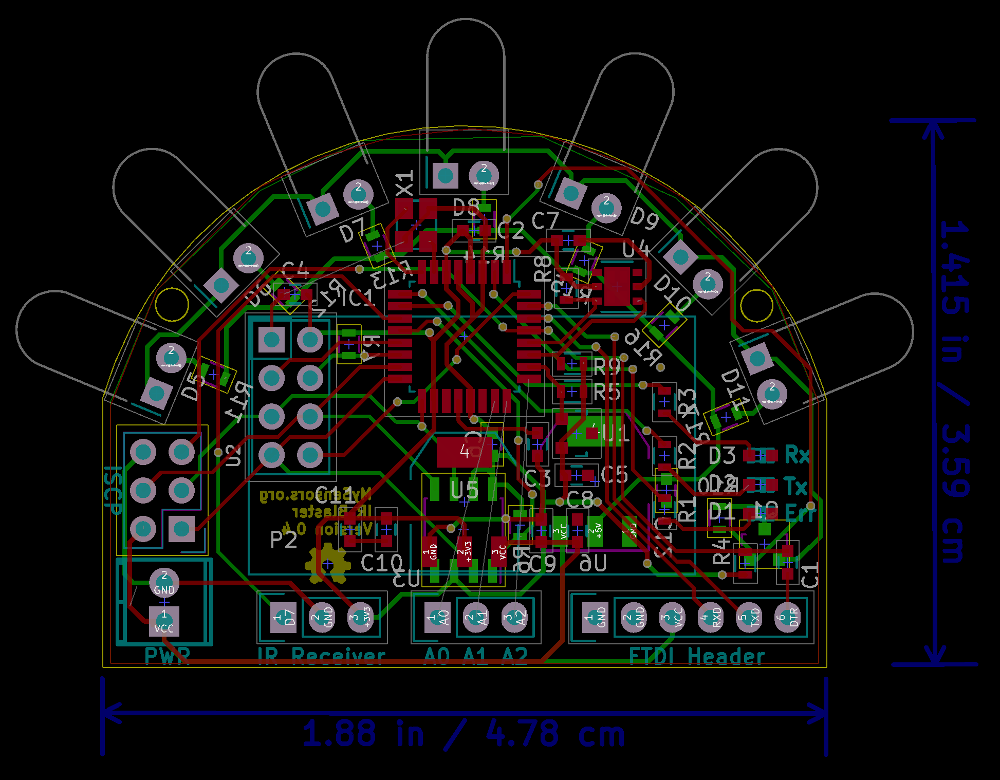
The goal is to reliably cover a 180 degrees field of view so the blaster can cover an entire room when placed in the horizontal center of a wall or in the corner of a room. To determine the IR LED angle and equal spacing, I defined 6 isosceles triangles that span 180 degrees. This yields the expected directional angles 30, 60, 90, 120, 150. Given the 30 degree difference, one option is to use the higher-luminance 20 degree IR-333-A LEDs for D5, D7 and D9 and interleave the lower-luminance 30 degree IR-333-C LEDs for D6 and D8; of course this means there might be a gap at the extreme edges of coverage (e.g. 0-10 degrees and 170-180 degrees) but that shouldn't be an issue for most users. Furthermore, while we will be driving the LEDs at maximum luminance, coverage holes will open up when the distance exceeds the angular displacement (see screenshots below). That said, I originally limited the blaster to 5 IR LEDs because I was limited to 500 mA through the transistor I selected but since we have now moved to a MOSFET, we can deliver 800 mA to the LED circuit so we could add two more LEDs to reduce the spacing to 22.5 degrees. Adding 2 more IR LEDs will increase the cost (larger board and 2 more LEDs) and I am not sure it is worth it given IR tends to bounce in most interior rooms. We might be better off just selecting different IR LEDs (hence why it is still an open issue). Thoughts (in the context of the tradeoffs)?
IR LED Angular placement overlaid on board outline
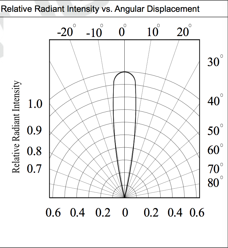
20 Degree IR LED
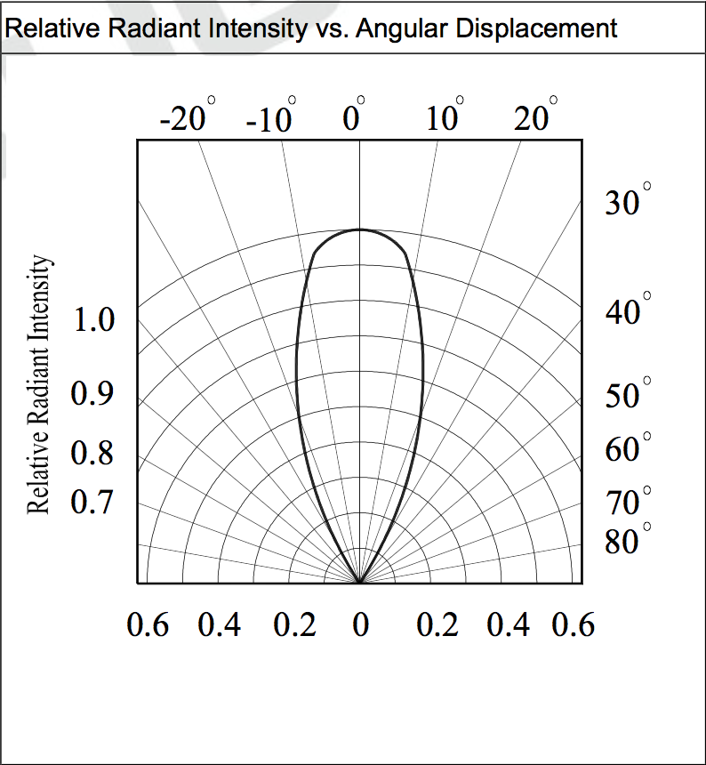
30 Degree IR LED
-
Hmm.. I don't have any favourite regulator at the moment. I think that an LDO is the way to go right now (for me) because it's a lot simpler design, and I don't have the needed time to qualify different switchmode designs :)
for the GW I just scavenged the net for 15 minutes, and found a suitable LDO (think it's capable of 0.5A, should probably have one thats capable of higher loads), didn't look that much on the datasheet (yet) as it's still in conceptual phase for me, putting in a couple of extra features each day, moving things around on the pcb, and trying to fit things in.
@tbowmo Sounds good. For now I will just stick with the AMS1117 series LDO because it is available in both adjustable and fixed (really simple), delivers up to 1A of current, handles up to 12VDC in, the SMD variants are SOT-223 and SOIC-8 and is in expensive. If you find something better, let me know ;)
-
Where did you find the symbol for the ams1117? If you created it yourself, could you add it to the mysensors kicad repo on github, so we have a common place for our symbols?
@tbowmo I created a custom symbol and used the standard SOT-223 footprint from the SMD Packages Library (associated as default footprint for symbol). I just updated the symbol to include a reference to the data sheet and tried to push it to mysensors_regulators.lib in the KiCad repo but it seems I don't have owner/write permission yet ;) Ping me once you update the permissions and I will push the changes up to GitHub.
-
Where did you find the symbol for the ams1117? If you created it yourself, could you add it to the mysensors kicad repo on github, so we have a common place for our symbols?
-
My wife and I were in Italy for the past 3 weeks with friends and family so I didn't have much time to work on the IR Blaster actuator. That said, the long flights back and forth from San Francisco to Italy afforded some concentrated time to finalize the design sufficient for public review before procuring a few prototype boards. To goal of this post is to solicit said feedback so "bring it on" after reading the details below.
@Sparkman - The biggest change is the addition of two more IR LEDs given we are now driving the circuit with a MOSFET (thanks @tbowmo) that can handle higher-current loads; this reduces the risk of IR coverage holes and increases the IR LED component options. However, I have not added a barrel connector for external LEDs to the PCB (yet?) because there are still open issues regarding circuit design to accommodate it (would welcome integration ideas).
I also have not laid the traces for A0, A1, and A2 because these are completely optional inputs, the 3 traces are difficult to place given the physical PCB layout and in fact they may not survive the final board.
Everything is in GitHub in case people want to review the details offline.
The PCB design follows - I had to increase the size of the PCB slightly to accommodate the two additional LEDs.
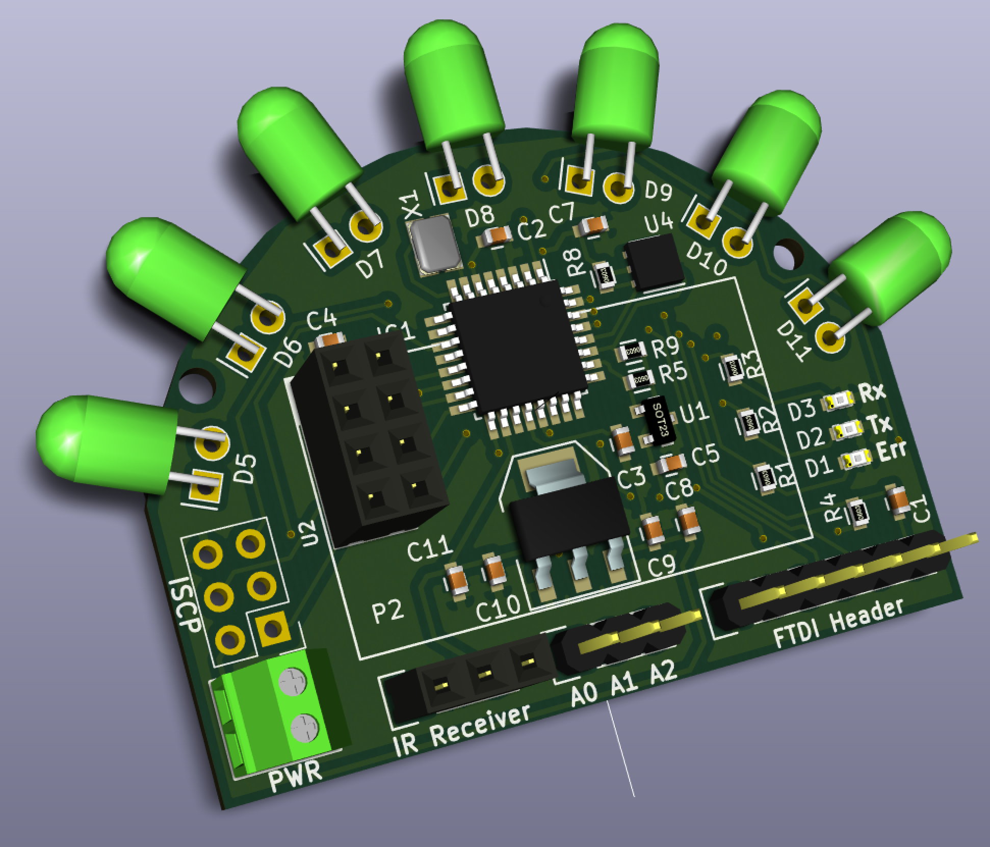
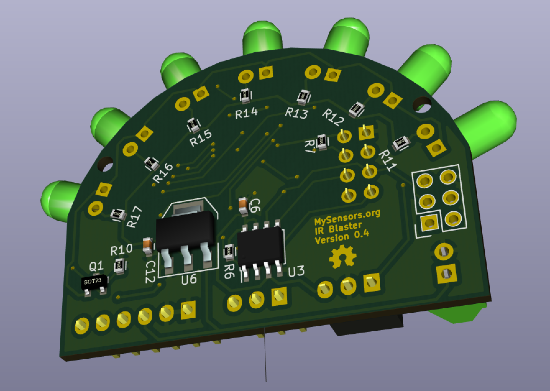
Here are two renders of the board, sans the radio daughterboard:
Finally, here is the version 0.4 schematic.
I have also developed a MySensor's IR Sensor Array that will enable me to measure the IR radiant intensity from different points in a room under varying ambient lighting scenarios. The test scenario is that an IR Sensor Array controller will illuminate the IR Blaster and then broadcast to all the IR Sensor Nodes to collect an IR measurement over a specified interval and report the IR level results back to the Sensor Array Controller at which point it will turn off the IR Blaster IRs and log the sensor node results for analysis. This should allow me to select IR LEDs to ensure maximum radiant luminosity without any IR coverage holes/gaps across the 180 degree radiance field. As an interesting side note, the development of the Sensor Array found a messaging limitation in the current MySensors.org library that @hek is planning to address in the next major release.
Ciao,
Bruce -
My wife and I were in Italy for the past 3 weeks with friends and family so I didn't have much time to work on the IR Blaster actuator. That said, the long flights back and forth from San Francisco to Italy afforded some concentrated time to finalize the design sufficient for public review before procuring a few prototype boards. To goal of this post is to solicit said feedback so "bring it on" after reading the details below.
@Sparkman - The biggest change is the addition of two more IR LEDs given we are now driving the circuit with a MOSFET (thanks @tbowmo) that can handle higher-current loads; this reduces the risk of IR coverage holes and increases the IR LED component options. However, I have not added a barrel connector for external LEDs to the PCB (yet?) because there are still open issues regarding circuit design to accommodate it (would welcome integration ideas).
I also have not laid the traces for A0, A1, and A2 because these are completely optional inputs, the 3 traces are difficult to place given the physical PCB layout and in fact they may not survive the final board.
Everything is in GitHub in case people want to review the details offline.
The PCB design follows - I had to increase the size of the PCB slightly to accommodate the two additional LEDs.
Here are two renders of the board, sans the radio daughterboard:
Finally, here is the version 0.4 schematic.
I have also developed a MySensor's IR Sensor Array that will enable me to measure the IR radiant intensity from different points in a room under varying ambient lighting scenarios. The test scenario is that an IR Sensor Array controller will illuminate the IR Blaster and then broadcast to all the IR Sensor Nodes to collect an IR measurement over a specified interval and report the IR level results back to the Sensor Array Controller at which point it will turn off the IR Blaster IRs and log the sensor node results for analysis. This should allow me to select IR LEDs to ensure maximum radiant luminosity without any IR coverage holes/gaps across the 180 degree radiance field. As an interesting side note, the development of the Sensor Array found a messaging limitation in the current MySensors.org library that @hek is planning to address in the next major release.
Ciao,
Bruce -
@ServiceXp said:
@blacey Really lovin this.. You plan to sell?
If there is enough community interest and demand, we (@hek et. al.) will offer the IR Blaster in the same fashion as @tbowmo's pioneering and very successful Sensebender Micro and hopefully in-development Gateway Device that I am personally jazzed about. Any proceeds from IR Blaster hardware sales will go directly to supporting the MySensors.org project (monthly hosting fees, etc.). So to answer that question we need to know who else would buy one if we make it available so we can estimate the batch size for an initial run. Anyone interested is encouraged to weigh in here.
-
I would be interested in at least one of them. (I'm thinking if we should add repeater mode into the firmware as a default?)
@tbowmo said:
I would be interested in at least one of them. (I'm thinking if we should add repeater mode into the firmware as a default?)
Cool and I'll sign-up for 4 Gateway Devices ;) I'm dead serious!
In my 1st gen one-off IR Blaster, I found that I need to repeat some IR Signals if that is what you mean by "repeater mode". I am using the HA Controller to repeat after some delay but it would make more sense to integrate the repeating logic directly into the firmware. I am planning pretty extensive IR reliability testing with the IR Sensor Array that I mentioned and I hope that repeating won't be necessary but some environments may have sufficient "noise" to require repeating. Perhaps it should be configurable (number of repeats and delay)??
I'm also thinking that a single IR Blaster should be able to control multiple devices in a given room so I'm planning to provide that as out-of-the-box functionality in the firmware. I don't know how I will do that yet but something akin to an array of child-devices that contains the child device type, manufacturer and IR code. The MySensor's library limit is 255 child devices per node so that should be sufficient ;)
I also think it makes sense to "lift" the self-tests that you developed for the Micro Sensor (flash and crypto chip).
Finally, I would love your expert review of the design before I order some boards for verification. I owe you a review of the Gateway Device that I will complete this weekend now that I am back on my home turf.
-
With the "repeater mode" I actually meant it to be a repeater for the mysensor network, so it double as both repeater and IR blaster.
Or maybe I would make a dimmer module, that could act as a repeater as well (I would add a couple of network repeaters around the house, as I have discovered some partially dead spots around here, where sensors are just on the edge of the reach of the RF signals)

