Rebuild of my broken 433mhz Cresta/hideki UV-Sensor
-
I just wanted to update this post with my code and rebuild to this UV sensor thanks to @core_c!
I also updated the box ;)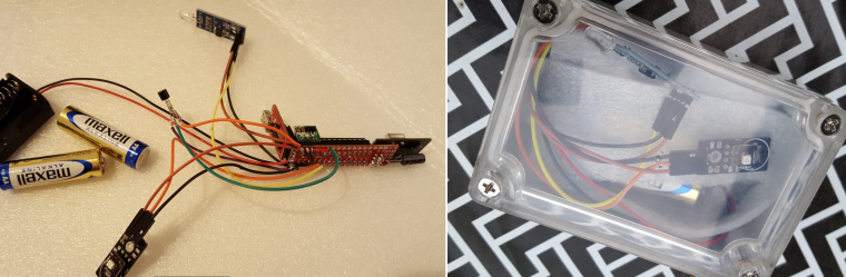
The Dallas temp sensor was never used in this project so please ignore...The node is build with a Slim Node. I could save some power by using a booster with VIn attached to D4. I keep the D4 low between sleeps. In sleep mode it consumes less than 10uA.
The code:
// Enable debug prints to serial monitor
#define MY_DEBUG

// Enable and select radio type attached
#define MY_RADIO_NRF24                  //The radio we use!
#define MY_NODE_ID 19                      //Fixed node ID
#define MY_BAUD_RATE 9600           //Needs to be defined because standard for MySensors is 115200. This bootloader uses 9600!

#include <SPI.h>
#include <MySensors.h>
#include <Vcc.h>

//SketchInfo MySensors
#define SKETCH_NAME "UV #19"                // Change to a fancy name you like
#define SKETCH_VERSION "1.4"                // Your version

//Light
#define CHILD_ID_LIGHT 1
#define LIGHT_SENSOR_ANALOG_PIN A0
#define SENSORS_POWER_PIN 4
MyMessage light_Msg(CHILD_ID_LIGHT, V_LIGHT_LEVEL);

//===================================================
// UVM30A ultraviolet detector.
//
// Thanks to core_c @ mysensors.org for code and info!
// The sensor's VCC is connected to +5V
//
// At first glance, the datasheet is not entirely making sense:
//  "输出电压" translates to "Output voltage", with a value of: DC 0—1V.
//  So the sensor will never output/measure the 2 highest values listed in the graph & table of the datasheet (1079 and 1170+).
//  The datasheet explains it: "(对应 UV 指数 0-10)" translates to "(corresponding to UV index 0-10)".  Fair enough.
//
//  "测试精度" translates to: "Test accuracy", with a value of: ±1 UV INDEX
//  That is not very accurate on a range 0-10. Example: if the real UV-index is 4, you could measure 3, or 5.
//  For that reason we take an average of multiple samples, to get a better measurement.

#define UV_PIN A1
#define CHILD_ID_UV 0
MyMessage uv_Msg(CHILD_ID_UV, V_UV);
const int UV_threshold[12] = {50, 227, 318, 408, 503, 606, 696, 795, 881, 976, 1079, 1170}; // // The list of UV index thresholds in units of mV

// The read value is a 10-bit value, ranging from 0 to 2^10-1 (0 to 1023).
// The reference voltage on the input pin is set to 1.1V.
// That voltage is spread out over the 1024 possible values of a sample.
// So our achieved resolution equals (1.1 Volts / 1024) = 0.00107421875 Volt.
// The UVM30A sensor datasheet lists all UV-index values according to measured milli-Volts.
const float SAMPLE_TO_MV = (1.1 * 1000) / 1024; // mV per sample-resolution

uint16_t UV_value;
uint16_t UV_index;        // the UV index
uint16_t UV_index_f;      // the fractional part of the UV index

// Compiler directives for averiging the UV-sensor readings
// (Change the values of UV_AVERAGE_T & UV_AVERAGE_N according to your own taste).
#define UV_AVERAGE_T 4000 // Sample interval duration in milliseconds..  (1 <= T <= 60000)
#define UV_AVERAGE_N 10   // ..During that interval, N samples are taken, and averaged.    (1 <= N <= 100, must be <>0)

#if UV_AVERAGE_T < 1      // Sanity check. It must be dummy proof
#define UV_AVERAGE_T 1
#endif
#if UV_AVERAGE_N < 1      // Sanity check. It must be dummy proof
#define UV_AVERAGE_N 1    // This value must be <>0 at all times, because we divide by it
#endif

// calculate once, use many times in the loop()
const float UV_AVERAGE_N_RP = 1.0 / UV_AVERAGE_N;
const uint32_t UV_AVERAGE_D = UV_AVERAGE_T * UV_AVERAGE_N_RP;
//===================================================

//SleepTime
unsigned long SLEEP_TIME = 600000; // Sleep time between reads (in milliseconds)

//Battery
const float VccMin   = 1.9;           // Minimum expected Vcc level, in Volts.
const float VccMax   = 3.0;           // Maximum expected Vcc level, in Volts.
const float VccCorrection = 1.0 / 1.0; // Measured Vcc by multimeter divided by reported Vcc

Vcc vcc(VccCorrection);

void presentation()  {
  // Send the sketch version information to the gateway and Controller
  sendSketchInfo(SKETCH_NAME, SKETCH_VERSION);

  // Register all sensors to gateway (they will be created as child devices)
  present(CHILD_ID_UV, S_UV);
  present(CHILD_ID_LIGHT, S_LIGHT_LEVEL);

}

void setup()  {

  analogReference(INTERNAL);

  pinMode(SENSORS_POWER_PIN, OUTPUT);
  pinMode(UV_PIN, INPUT);
  pinMode(LIGHT_SENSOR_ANALOG_PIN, INPUT);

}

void loop()
{

  digitalWrite(SENSORS_POWER_PIN, HIGH);  //Set power on digital pin for lightsensor.
  wait(500); //Wait 500ms to make sure lightsensor is powered and stable.

  processUV();   //Read UV

  readLightLevel();   //Read Light

  digitalWrite(SENSORS_POWER_PIN, LOW); // Set power for lightsensor off to save power.

  BatteryCalculation();

  //Sleep!
  sleep(SLEEP_TIME);
}

void readLightLevel()      {
  int lightLevel = (1023 - analogRead(LIGHT_SENSOR_ANALOG_PIN)) / 10.23; //To get a value ranging from 0 (dark) to 100 (bright).

#ifdef MY_DEBUG
  Serial.print("Light: "); Serial.println(lightLevel);
#endif
  send(light_Msg.set(lightLevel));

}

//===================================================
// Process a UV measurement:
// read an average value from the UV detector.
// The average consists of N samples taken during a T milliseconds interval.
//===================================================
void processUV() {
  // Set the reference voltage for sampling
  // For our ATmega328 Nano: INTERNAL = 1.1V, DEFAULT = 5V
  // After using analogReference(), the first few samples may not be accurate (according to the Arduino language reference),
  // and that is why we read a few dummy samples before starting the actual measurement.
  // NOTE: If you change the next statement, beware to adjust the value of SAMPLE_TO_MV too.

  for (int i = 0; i < 10; i++) UV_value = analogRead(UV_PIN); // ignore the possibly inaccurate samplevalues.

#ifdef MY_DEBUG
  Serial.print("UV raw values: [");
#endif
  uint32_t average = 0;
  for (int i = 0; i < UV_AVERAGE_N; i++) {
#ifdef MY_DEBUG
    UV_value = analogRead(UV_PIN);
    Serial.print(UV_value);  Serial.print(" ");
    average += UV_value;
#else
    average += analogRead(UV_PIN);
#endif
    delay(UV_AVERAGE_D);
  }
  UV_value = average * UV_AVERAGE_N_RP;
#ifdef MY_DEBUG
  Serial.print("]    avg: ");  Serial.print(UV_value);
#endif

  // We must convert sample-values into mV-values before we look up the UV-index.
  UV_value *= SAMPLE_TO_MV;

#ifdef MY_DEBUG
  Serial.print("     mV: ");  Serial.print(UV_value);
#endif

  // determine the UV index
  if (UV_value < UV_threshold[0]) {
    // too low value  or  invalid value (in case the sensor is wrongly connected it always returns 0)
    UV_index = 0;
    UV_index_f = 0;
  } else {
    for (UV_index = 11; UV_index > 0; UV_index--) {
      if (UV_value >= UV_threshold[UV_index]) break;
    }
    // calculate fractional part of the UV-index
    if (UV_index == 11) {
      // already at the maximum level; Displaying a fraction is meaningless
      UV_index_f = 0;
    } else {
      UV_index_f = map(UV_value, UV_threshold[UV_index], UV_threshold[UV_index + 1], 0, 9); // one decimal, so a number ranging 0 to 9
    }
  }
  float UV_index_float = UV_index + (UV_index_f * 0.1); // that is the same as /10

#ifdef MY_DEBUG
  Serial.print("     UV index: ");  Serial.println(UV_index_float);
#endif

  send(uv_Msg.set(UV_index_float, 1));

}


void BatteryCalculation()
{
  float v = vcc.Read_Volts();

#ifdef MY_DEBUG
  Serial.print("VCC = ");
  Serial.print(v);
  Serial.println(" Volts");
#endif
  float p = vcc.Read_Perc(VccMin, VccMax);

#ifdef MY_DEBUG
  Serial.print("VCC = ");
  Serial.print(p);
  Serial.println(" %");
#endif

  sendBatteryLevel(p);

}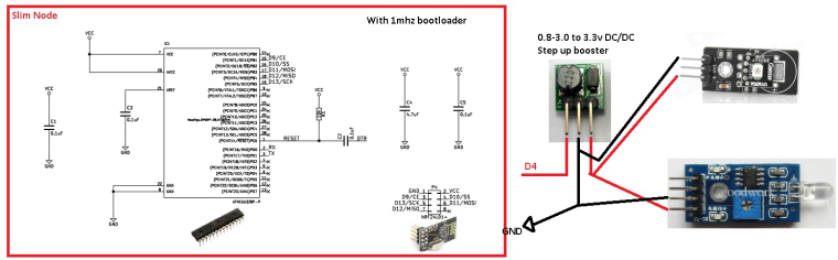
And offcourse the sensors analog output was connected to analog input of the atmega - forgot that in the schematics. UV=A0 and Light =A1 -
So is the UVM-30a still the prefered sensor for this implementation or are there any better options?
The ML8511 was mentioned but it was not yet confirmed to be working.
Does connecting a booster to an output pin that is turned of work as expected? Does not the booster try to boost even if the output pin is low?
- Tomas
-
So is the UVM-30a still the prefered sensor for this implementation or are there any better options?
The ML8511 was mentioned but it was not yet confirmed to be working.
Does connecting a booster to an output pin that is turned of work as expected? Does not the booster try to boost even if the output pin is low?
UVM-30a still the prefered sensor
Cant say. I have been using this for the last year (wrong apparently) but worked as expected.
Does connecting a booster to an output pin that is turned of work as expected? Does not the booster try to boost even if the output pin is low?
I dont know what will happen over time so I have to come back to that but I had a reading of 5uA in sleep mode which to me indicates a success. I did so because one of the sensors has a minimum of 3.3v and that would stop working pretty soon. Since the rest of the system should be able to go lower I wanted to test... the node is really stable and working great so far!