
Roller Shutter
-
@jserfaty I will try to share some code as soon as possible, sorry being late on this. Bzzz, bzzz I'm like a bee sometimes :laughing:
In sketch, I will have two options:- automatic calibration with current sense..
- or a fixed calibration, a time travel set in sketch.
So I will try to look if I have nothing ugly in my sketch asap (there is already someone waiting for this ;))
And a note, for others, about the board, I'm thinking to reduce size if possible to fit better in wallbox but I would like to keep hilink. -
Maybe look at this one: Arduino shutters
I am using this one with my 8ch relay board. Working fine here!
-
@kenci yep I am using this one ;) it's time based in the sketch. and nice class.
I just need to add an auto calibration if using current sensor -
-
@scalz are you going to sell this on openhardware.io as a complete module?
-
@kenci I think so...this is a very nice new feature on openhardware, not only for commission (sure that could help a little bit for dev cost..) but, more interesting is to have competitive price for some device and make these available for others, that's excellent :) I can't wait to test this, to see what will be the quotation..I will try to do my best ;)
-
Hi @scalz great work i am working a project like yours but i do not understand teh principle of MDC3105. The shematic i made like yours is below, search a little but don't find anything about it. Is it correct without any resistor, diode etc.?

The normal schematic is below with diode, resistor, transistor etc.

Thanks for share it.
-
Hi @scalz great work i am working a project like yours but i do not understand teh principle of MDC3105. The shematic i made like yours is below, search a little but don't find anything about it. Is it correct without any resistor, diode etc.?
The normal schematic is below with diode, resistor, transistor etc.
Thanks for share it.
@ddos Yes, that would work - if VIN1 is pin 5, VOUT1 is pin 6, VIN2 is pin 2 and VOUT2 is pin 3, that is.
It's a bad habbit to have "double pins" in the schematic. You should really make a pin for each ground connection - just my 2 bits.
BR Jonas
-
-
@ddos
jballing is right. the relay driver already handle this. it's integrated, less footprint. be careful playing with AC, you need to know what you do ;)btw I am a bit cheap on pics and late I know :blush: a bit busy too but few pics of what it looks..
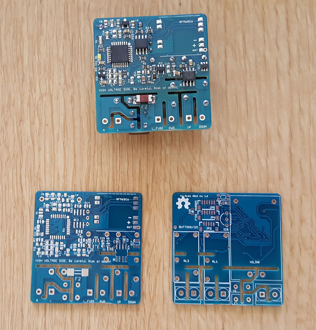
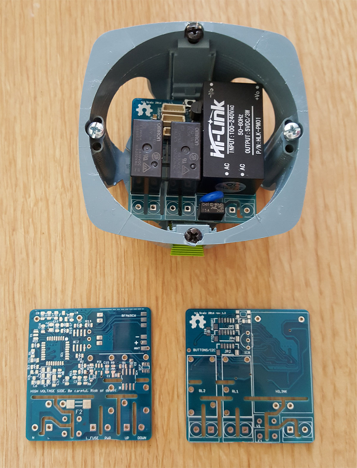
45x44mm seems to fit ok. millings for additional distance etc...
-
@jbjalling thanks for your quick reply. If this is gonna works without any additional parts my board has more space. I copy the device @scalz schematic i am going to do new library with two GND for it thanks again.
-
-
-
@ddos
thx. of course! i will print an insulating box with some air vents. and i will add some liquid tape for isloating the pads ;)for software, i need some time to clean and test it. and i am playing with others things+ etc.. I already shared the sketch with only one beta tester here, for the moment. but of course i will share it asap :)
-
-
@ddos
thx. of course! i will print an insulating box with some air vents. and i will add some liquid tape for isloating the pads ;)for software, i need some time to clean and test it. and i am playing with others things+ etc.. I already shared the sketch with only one beta tester here, for the moment. but of course i will share it asap :)
-
-
-
-



Hello! It looks like you're interested in this conversation, but you don't have an account yet.
Getting fed up of having to scroll through the same posts each visit? When you register for an account, you'll always come back to exactly where you were before, and choose to be notified of new replies (either via email, or push notification). You'll also be able to save bookmarks and upvote posts to show your appreciation to other community members.
With your input, this post could be even better 💗
Register Login