Safe In-Wall AC to DC Transformers??


  • Hardware Contributor

    Yes, if you read the threads about this - we have alof of those examples... thats why we are using the HLK-PM01 and are having this discussion. That link is not about the HLK-PM01 @punter9

    Edit: that guy you linked to tested the HLK as well:

    "While it is not great, I would consider using it on my own projects, however it would need filtering on the mains side if I was going to use it in a project I was going to place on the market (read as sell), as under my control I can keep an eye on it causing unwanted interference with other equipment, this is why we have the limits set in the standards."

    and if you read our conclusions from this thread its the same.


  • @sundberg84 Did you see it? The guy is using fuse (Farnell part number 2464451) and varistor (Farnell part number 1004390) for HLK-PM01. It is 0.8A fuse


  • Hardware Contributor

    @alexsh1 Yea i saw it - and the text say: "I got this generic even cheaper board" - its not a HLK he is testing...


  • Hardware Contributor

    @alexsh1 - Yea, ok - we have discussed that test above in this thread as well.
    As far as I know the HLK is the best so far.

    We also have another test where we have got different advice about fuses, (normal/temp) and varistor (see above).
    Im accually using a 0,2A fuse for 240V. Read through this post if you are interested - its a great discussion.


  • @sundberg84 I have gone almost through the whole topic. Excellent discussion!

    I think the difference is that you are using the slow blow fuse 0.2A and he is using fast acting 0.8A one. I really wonder which one would be more safe. I know slow blow fuses are used with inductive load (like motors), but not sure about this application.

    I know it has been mentioned here as well, but did you make any provision for a thermal SEFUSE (say, 73C) or do you think it would be too much?


  • Hardware Contributor

    Let's hope skippy.org.uk also will recommend some good EMC line filters for the HLK-PM01 soon.


  • Hardware Contributor

    And about that cheap converter test. Since is an open type one with high res pictures from seller - too bad he didn't test an arbitrary other where the failed "visual inspection" could have passed simply by a look at the pictures. (I even think those blue caps could be small ceramic safety ones).

    Btw, found a version of EN 60335 here.


  • @m26872 said:

    Btw, found a version of EN 60335 [here].

    I've used this link


  • Hardware Contributor

    @alexsh1 Thanks, it was better in every sense.


  • Hardware Contributor

    @alexsh1 said:

    I think the difference is that you are using the slow blow fuse 0.2A and he is using fast acting 0.8A one. I really wonder which one would be more safe. I know slow blow fuses are used with inductive load (like motors), but not sure about this application.

    I know it has been mentioned here as well, but did you make any provision for a thermal SEFUSE (say, 73C) or do you think it would be too much?

    Its a good a releveant question... im not sure about slow or fast, but when i read the slow blow can tolerate high levels of voltage for a short period and a fast (or quick) blow fuse is a fuse that bursts instantly when high power voltage is passed through it.

    How i see it, we have the protection against high quick power voltages allready in the Varistor? (Im not educated in this - this is my brain/logic trying to add everything up). Allthough what i read is what you are saying - slow blow are often used in motors and fast blow on home appliaces.

    In my PCB I use a 73dgr therma fuse as well, im using the exact same circut that petewill has in its first post in this thread.


  • @sundberg84

    The varistor is against high voltage transients and surges. The fuse is for overcurrent.

    I have just ordered 0.8A fast blow fuses - they will be installed on my boards.


  • Hardware Contributor

    @alexsh1 - yes offcourse, you are right - mixed that up.
    I have some 0.5 fast blow - sounds like thats a better idea than slow blow @petewill.


  • @sundberg84 Given that HLK-PM01 can withstand current spikes to 1.0A, I decided to go for a 0.8A fast blow fuse. Additionally, having a thermal fuse would be an advantage, but not a must. Unless you want to push the PSU to around 600mA then it is going to operate close to its limit and you need some extra protection


  • Hardware Contributor

    @alexsh1 - what do you base it on, its not a must? Im trying to be as safe as possible 🙂 but i really wants to learn as much as possible about safety regarding ac/dc converting.


  • @sundberg84 Obviously, there is no harm from having it, but if your consumption is, say, 150ma and the PSU is handling 600ma, this is just an extra in my view.

    Did you see the IR images taken after about 45 minutes of operation over here?


  • Hardware Contributor

    @alexsh1 said:

    150mA

    Ok, sounds logic - tnx. If I want to run a relay and some sensors it might be higher than 150mA so I like the extra safety 🙂 Yea, have read that review about 100 times now, and emailed the dude as well for questions, haha. Much to learn!


  • Admin

    @sundberg84 said:

    @alexsh1 - yes offcourse, you are right - mixed that up.
    I have some 0.5 fast blow - sounds like thats a better idea than slow blow @petewill.

    Are you guys sure you're not confusing the input current with the output? In the above mentioned review he says there is a "Maximum input current: <0.2A" which is the reason for the slow blow fuses (I think). Or, maybe I'm misunderstanding and you're talking about adding an additional fuse to the output of the HLK?


  • Hardware Contributor

    Yes, max input is 0.2A with spikes ok upp to 1.0A but
    @petewill we were discussing about using slow or fast blow fuse on the input.

    Slow blow seems to be more for motors and allowing equipment making spikes when they start up. Then the fuse wont blow due to a higher current during start. In home appliances it seems its a fast blow fuse we should use.


  • Hardware Contributor

    Found what seems to be a interesting article: https://www.ieee.li/pdf/essay/safety_considerations_in_power_supply_design.pdf (Texas instrument).
    Not read through it or know if the source is reliable but Texas instrument seems like a good author/source. No references inside so I guess its "how they see it".


  • Admin

    @sundberg84 Ok, I understand. I will defer to the experts here and update the first post when a consensus is reached. I do have one more thing I'd like clarified though. It still seems to me like a 200/300mA slow fuse would be better as it would survive small over-current spikes but it wouldn't allow sustained draws over the HLK's rating of 200mA. With a 600mA fast blow fuse the HLK could draw 500mA as long as it wanted without blowing. Maybe this doesn't matter though?

    On a side note, when I tested one of my slow blow fuses it still blew pretty fast with a moderate load above it's specs. I tested with a 33 watt floresent bulb and it blew in less than a second (not sure of the exact time/wattage as it was really just a test to see if it was a fuse and not something else).


  • Hero Member

    Transformers typically have an in-rush current as well, so a fast-blow fuse could pop because of this if it's not sized for that.

    Cheers
    Al


  • Hardware Contributor

    Interesting @Sparkman!
    https://en.wikipedia.org/wiki/Inrush_current "When a transformer is first energized, a transient current up to 10 to 15 times larger than the rated transformer current can flow for several cycles."


  • Hero Member

    This in-rush 'effect' can be seen on any induction load.


  • Hardware Contributor

    I´m no expert but I thought and researched some. Could be wrong, please correct me then.

    I think you're confusing AC inductive load inrush current with what we're interested in, which is the inrush to our switched power supplies. In our case the inrush current is to the primary side rectifier filter capacitor, not to the transformer. The transformer inside SMPS is for high frequency and would probably give a small inrush even if it was subjected to normal AC. Now it's DC and behind the switch controller and FET. And the controllers I've seen usually have some start-up time.

    General about fast/slow types of small fuses (from here😞

    The fuses must not open in less than one hour at 125% of rated current and open within two minutes at 200% of rated current. The 1000% overload is used to determine the fuse characteristic. The opening time for each rating is listed below.
    Type FF: Less than 0.001 sec.
    Type F: From 0.001 - 0.01 sec.
    Type T: From 0.01 - 0.1 sec.
    Type TT: From 0.1 - 1.00 sec.
    These characteristics correlate to the terminology used in IEC 60127-1.
    

    So in theory a type FF fuse could open "instantly" for 10*In (rated current) ? (in reality you check its specs of course). But let's see how a more normal type F fuse would work given the setup from a "normal" SMPS. I use this, but from what I've seen, primary side looks very similar to the HLK-PM01.

    Rectifier filter cap value of my SMPS: 4.7uF
    A normal 5x20mm fuse resistance value: 5 ohm (usually more resistances than just the fuse, but let's be conservative)
    Max voltage peak-peak 700V ( ~250Vrms )
    Regular capacitor calculation:
    I(t0) = U/R = 140 A
    T = RC = 54.7u = 23,5 us
    I(t) = U/R
    e^-(t/T) = 140*e^-(t/0.0000235)

    How much inrush current do we have at for e.g. the fastest F-type fuse characteristic:
    I(tmin=0.001) = 140e^-(0.001/0.0000235) = 140e^-(1/0.0235) = 3.3*10^-19 (i.e. zero current)

    How much time until I=0.1A (which would correspond to fuse value 0.01A):
    I=U/R*e^-(.) <=> e^-(.)=IR/U <=> (.)=-ln(IR/U) <=> t = -ln(IR/U)0.0000235
    t = -ln(0.1
    5/700)*0.0000235 = 0.00017 = 170us

    So even a 0.01A type F fuse should be far from blowing in a worst case and with conservative assumptions. For extra fast fuses, type FF, the characteristic must be checked.

    Edit: This is only regarding the inrush, of course the load must be added to this eventually.


  • Hardware Contributor

    @m26872 So, to sum up - there is no need to use a slow fuse, since the in rush current isnt "long" enough to blow a fast fuse. So considering safety (and if you have the same mA value for both fuses) its better and should work to use a fast rather than slow ??


  • Hero Member

    @m26872 I'm no expert either. 😃 We may be saying the same thing however... I don't think it matters (AC or DC), if there is a transformer in the circuit, there is going to be a current peak on startup. If you have a filter cap before your transformer, you will see 2 peaks. The first one will be caused by the capacitor charging up, and the second from the inductive load caused by the transformer powering up. I'm thinking the 2nd peak should be much less due to the filter cap.

    Of course I could be all wrong. 😣


  • Hero Member

    Here is an interesting article http://www.vptpower.com/wp-content/uploads/downloads/2012/01/info_inrushCurrent.pdf on the subject. Looks like there is a LOT more to it (not that I thought there wasn't) than my over simplified post above.


  • Admin

    @m26872 Thanks! So, am I understanding this correctly that we would want a 200mA or 300mA fast blow fuse? Since I know some of us have already purchased the 300mA slow blow fuses do you think it is safe to use them? If I'm understanding correctly they should still blow relatively quickly if they are subjected to high current right?


  • Hardware Contributor

    @sundberg84 Yes, a fast fuse should give a higher level of protection without issues.

    @RJ_Make That second "inrush" is what I called the load. It's completely governed by the controller and should not stress the fuse more than running overloads. If there's a peak it´s because of capactive load on the output and has nothing to do with the transformer.
    Thx for the link. It confirmes that these turn-on-times are a few milliseconds just like the HLK-review said (around 3ms). No chance to superimpose the first peak.

    @petewill Regarding fast fuse, yes. But the value I don't know. The HLK review shows overload capabilties, but I don't know about the input currents at that point. Honestly I think it's very unlikely that you'll be saved by using a fast fuse instead of a slow. It's more a matter of e.g. better varistor (overvoltage) protection and the personal feeling of maximum safety etc.


  • Hardware Contributor

    So there is another safety issue we should discuss for the HLK.
    Creepage (separation between two solder eyes measured along the surface) and clearance (shortest distance between as measured through the air) on the AC input.

    According to datasheet there is 5mm center-center, but real distance with solder and pads its more like 3, maybe 3.5mm.

    I found this and this which was a great summary of some IEC standards states that if your are going to use 240v and put the HLK into a environment with pollution degree III higher you need more creppage than 3.2mm. What am i saying? If i understand this right its not safe to use the HLK in any environment where moisture condensation may occur (outside, bathroom). My guess when i try to read the contamination groups is that if you put the HLK inside a sealed case you get the contamination level down to 2 and then we are safe above needed 2,5mm.

    To be on the safe side I have in my latest pcb added holes between AC input to increase creepage:

    0_1456695808093_1.JPG

    Am i right? Dont know - its hard to read all these articles and Im new to this so please bring anything to the table... corrections, questions or thoughts.


  • Hardware Contributor

    @sundberg84 I think that looks like an excellent idea. I was looking at the tear down of the HLK in the test that was run and it doesn't look like there was any reason for them to do this - at least as far as I could see, there was plenty of room to put those connectors at the corners like the DC side.


  • Hardware Contributor

    @TD22057 Yes, you can see in the teardown they have thought about the creepage in the optical feedback unit (cut a hole in PCB) between primary and secondary. I dont know why they so close, but 5mm is enough - maybe they forgot about solder/pads would take some space?

    @alexsh1 If i understand Contamination levels right the difference between III and II is that in III occurs conductive contamination so if you seal it up this should get it down to II.

    Then there is a difference between materials - and if compare material I and III its a big difference in creepage - does anyone knows what this means? What material is a normal PCB?


  • Plugin Developer

    Maybe they put the pins closer on the AC side than on the DC, to make sure people would not put the unit the wrong way, which could be dangerous? But as you say, they should have done a better job, though.


  • Hardware Contributor

    @martinhjelmare - thats a great thought - must be so, but if you think safety they should do the other way around, ac side wide apart and dc closer.


  • Plugin Developer

    @sundberg84

    Yeah, 😄 , they really screwed that up. Unfortunate, when the rest of the design, seems so good.


  • Hardware Contributor

    Some more info about Material Groups and CTI reagarding creepage. When i read PCI datasheets with FR-4 material from different pcb manufactures it looks like we are in the III group (worst offcourse).

    PCB in better groups (and better CTI) can be found offcourse - just add money.
    Also found a clearance and creepage calculator: http://www.creepage.com/


  • @ceech : Is there a chance to get your design data for this board?


  • Hardware Contributor

    This solution, if well build locks a lot safer than a standard phone charger. The overheat protection is something that I like a lot. Is ther any pcb that only haves this solution? I found one in the OpenHardware but it integrates the node, I would like some stand alone solution! I think that I will give KiCad a go and try to develop one!


  • Hardware Contributor

    So just to bring the attention back to the fuse situation since the last update on the original post was in December;

    Am I correct in thinking that we're supporting the use of a fast blow fuse and optionally a 4.7uF Capacitor on the AC side of the transformer/converter?

    My initial thoughts before being directed to this topic was to have the Capacitor on the AC side of the circuit along with a slow blow and thermal fuse, then on the DC side of the converter to have a fast blow fuse for the low power circuitry along with the filtering caps.

    The reason why i thought this, i have zero experience in this department though, is that the slow blow fuse on the AC side would allow for the inrush spikes from the transformer and the capacitor charging and then the fast blow fuse would stop the dc components from being fried from sudden spikes of DC current. Again, i have no experience here and hence the reason i'm posting this. Do you think that maybe i'm being a little too over the top with trying to protect my DC components?


  • Hardware Contributor

    Hello all, I finished my version of this solution! I used a ATMEGA328, this will make it cheaper. https://www.openhardware.io/view/83

    I need some help validating the layout, most important the 220v traces and the capacitors used in the layout!

    Thank you all


  • Interesting circuit.
    http://www.homemade-circuits.com/2012/03/how-to-make-simple-12-v-1-amp-switch.html

    Digchip circuit detail.
    http://application-notes.digchip.com/005/5-10593.pdf

    This circuit has VIPer22A it is similar with AP8012 of Hi-link.
    NTC Resistor for Temperature Protection.
    (With NTC, resistance Decreases with temperature to protect against inrush overcurrent conditions. Installed series in a circuit.)

    VIPer22A Datasheet:
    OVERTEMPERATURE, OVERCURRENT AND OVERVOLTAGE PROTECTION WITH AUTORESTART

    It is easier to buy Hilink, but I found it has interesting things.


  • "Performance test and review of mains to 5V 0.6A Hi-Link HLK-PM01"
    http://lygte-info.dk/review/Power Mains to 5V 0.6A Hi-Link HLK-PM01 UK.html


  • Hardware Contributor

    Hello, I'm looking for 200mA slow blow fuses, I looked ebay and AliExpress, but I can't find it! Does any one haves a seller?


  • Hardware Contributor

    @Soloam said:

    Hello, I'm looking for 200mA slow blow fuses, I looked ebay and AliExpress, but I can't find it! Does any one haves a seller?

    Just a quick search brings up a few options. I have linked you towards two of them;

    http://www.amazon.com/Qty-200mA-Slow-Blow-T200ma-GDC200mA/dp/B004TN2ZGG
    http://www.ebay.com/itm/5pcs-MJS-200-R-0653-0200-11-FUSE-0-2A-125V-200mA-SB-SLOW-BLOW-AXIAL-LEADS-5X15mm-/111902926482?hash=item1a0def2692:g:e2YAAOSwzgRWvdRe


  • Hardware Contributor

    Hi @Samuel235 thank you, but the shipping cost from amazon to my country would be a lot! I was looking at Ebay and AliExpress, but I can find Fuzes 250v 3.6x10mm Slow Blow of 200mA!

    The only one that I found where this http://www.ebay.com/itm/111433875797?_trksid=p2057872.m2749.l2649&var=410420838583&ssPageName=STRK%3AMEBIDX%3AIT&rmvSB=true! But the 200mA are out of stock!

    I wanted 3.6x10mm because of the size of the board where I'm going to use them, 250V is my country AC voltage (Europe, Portugal), Slow Blow because I think it would work better, and 200mA because that is the HK max current.


  • Hardware Contributor

    After some searching I can't find the 200mA fuses on 3.6x10 mm size and with Axial Leads! I think I'll go with the 300mA type!


  • Hardware Contributor

    I'm just having a quick look through the specs of the HLK-PM01 and it has a stable current draw of 600mA with a burst draw of 1A. Would i be wrong in giving this a 1A slow blow fuse to protect it, or should it be smaller? I see most of people are going for a 300mA fuse here but i'm a little confused on why you would do that if the HLK-PM01 is safe to burst draw 1A?


  • @Samuel235 I have a fast blow fuse 800mA and in terms of slow blow fuses,I think 300mA is spot on. Why are you looking at the hlk-pm01 specs? You should be looking at consumption current. Yes, hlk-pm01 can provide a stable 5v at 600mA, but is it relevant for our project when the consumption is probably below 200mA?

    If you are looking at something more power hungry the values have to be altered accordingly.


  • Hardware Contributor

    @alexsh1 basic principles. I've been going round and round in circles regarding another project for weeks it seems to have made me insane. Thank you for pointing out basics to me.


  • Hi all...

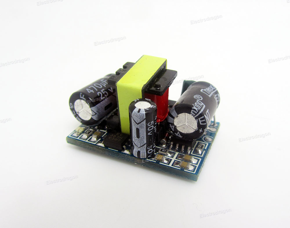
    I've recently received 20 of these units (see picture below) and hooked all but two of them all up to 240v with a dummy load resister to test. The other two are driving MySensor nodes to make sure there are no unexplained resets etc. They are well made and are claimed to be a "Mature" and stable unit. So far, no smoke and the ones on nodes have not reset, so all looks well. They have temperature protection, overcurrent, overvoltage and short circuit protection.

    I went for these rather than the HLK-PM01 because:

    • Being an open PCB, i can easily attach a lead onto the low voltage AC side of the transformer for use by the EMon Energy Meter library in calculating the actual AC voltage in order to derive more accurate power usage.
    • The other thing I like is they are not a 'potted blob' - while the blob is a lot safer with regard to errant fingers etc, I feel they must run a lot hotter, and heat not only causes components to die, I figure it could increase the fire risk?

    And the final factor being that the price is a bit over one euro, making them the lowest cost AC power supply I've come across for nodes.

    Product link: <click me>

    FWIW: All the regular "Express" freight charges from China to Australia are about AUD$25 to $30, but this supplier offered an express courier for $7 (US$5) - When it sounds too good to be true. . . Well, the goods were collected from the supplier in China on Wed mid-day, and arrived at my door at noon on Friday. When you consider I live 100Km outside of the main city (Perth), which normally adds two additional days onto any delivery, this was utterly amazing!

    Cheers,

    Paul
    alt text


  • Hardware Contributor

    @AffordableTech, I was looking at these not too long ago. I wish i could get my hands on these in the UK for that sort of price! I too like the open PCB style rather than the HLK-PM01, just like yourself as all of my projects are inside of boxes or hidden away from human reach some way.

    I'm tempted to purchase this just to have a little investigation on the quality of the item....


  • Hardware Contributor

    @AffordableTech - the temperature in the HLK is not a problem. I have measured it running a 5v node, relay and some sensors attached with everything put inside a wall. It never goes above 35dgr C. Also having a open PCB with the possibilities to get to the hot traces has it positive things but are not safe and does not meet any safety regulations.


  • Hardware Contributor

    @sundberg84 I remember spending an hour reading through that. Huge in-depth review you did concerning properties such as temperature with thermal imaging camera under load. Am i thinking of the right one? Thank you for that by the way!


  • @sundberg84 - its all about one's point of view. I recently met two English ladies on holiday here, they were on the verge of serious heatstroke, because as they said, "at home 23 degrees was a record summer for us" - it was a very pleasant pleasant 35C day. Days later we began a straight week of 40C plus. That's when all the "E's" die like flies "Electronics" & "Englishmen"😰.

    In your (truly excellent) tests, the HLK PM01's peaked at 60C under top load - but I suspect that test was performed in a veery laaaarge ice-box 😉.

    Paul


  • Hardware Contributor

    @AffordableTech - Not my test (the big excellent one with 60C). I did one myself (see Inwall AC/DC PCB on openhardware for diagram). I didnt top load it, I used a normal load (Normal MySensors node with some relay and stuff) and reached 35dgr C only.

    This is good for me - i rather have the safety but as you said - its one's point of view what you find most important. 🙂

    And no, no cooling at all on my test 😉


  • Admin

    @Samuel235 & @alexsh1
    I know this is a late response but I just wanted to clarify. The 200mA or 300mA fuse is supposed to go on the mains side of the HLK. The max draw from the mains side is 300mA (if I remember correctly). It is meant to kill power (and prevent fire or other damage to your property) to the entire circuit in case of any issues.


  • Hardware Contributor

    @petewill, thank you. I already knew where to place it but thank you for the warning. However because you have made me aware of the current draw of the HLK i went to the datasheet and found:

    0_1464014007213_image.png

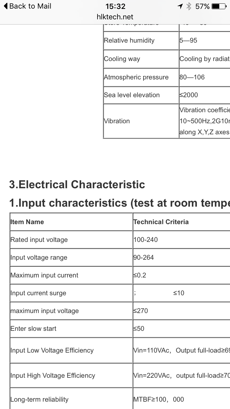
    So thank you for making me aware of this! Not sure why i was looking at the output current and not the input.


  • @petewill Good point - thank you! However, I have raised a different argument concerning the fast blow fuse vs a slow blow fuse. This was discussed already with @sundberg84 in this thread.


  • Hardware Contributor

    @alexsh1, you did indeed. I remember questioning why in a previous reply because i had concerns that a fast blow would be better suited but then you guys pointed out that the slow blow is the slightly better option in this use case since there is a large current draw at first with the transformer, was this the outcome that i remember?


  • Hardware Contributor

    Here was my contribution to this discussion. https://forum.mysensors.org/topic/3428/my-look-at-a-cheap-12v-power-supply

    Perhaps not very elaborate, but I'm in favour of the 'fast' fuse. But not extra fast.


  • @Samuel235 it is subjective. 300mA slow blow fuse will not cut it off if the current is 300mA or slightly above for a short time whereas the fast blow fuse will (at the higher current though in our example as you do not want to burn the fuse due to a spike). Unless you have a very sensitive electronics, in my experience both fuses would provide you adequate protection. In some cases (engines), you have to use a slow blow fuse as the start up current may blow the fuse.

    Personally, I'm very much in favour of the fast blow fuse in this setup


  • Hardware Contributor

    To quote myself from a few posts above regarding fuse characteristics. As you can see it's not an art of precision.

    "
    Thee fuses must not open in less than one hour at 125% of rated current and open within two minutes at 200% of rated current. The 1000% overload is used to determine the fuse characteristic. The opening time for each rating is listed below.
    Type FF: Less than 0.001 sec.
    Type F: From 0.001 - 0.01 sec.
    Type T: From 0.01 - 0.1 sec.
    Type TT: From 0.1 - 1.00 sec.
    These characteristics correlate to the terminology used in IEC 60127-1.
    "

    At >10xIn (1000%) I want it to be fast and safe, where as frequent running currents between 1.25-2xIn should be minimized due to wear and false blows. Type FF could be to sensitive from looking at my measurements. Hence I choose Type F.


  • Hardware Contributor

    Would you agree with me when i say;

    I think it is safe to have a slow blow fuse on board no matter what and then include a fast blow Type F or Type FF at super cautious needs, if you have sensitive electronics such as RF Radios, ICs that are very sensitive. However if we would like to be picky about the choice, any circuit that has a in-rush surge of current when turned on we need a slow blow fuse, anything that doesn't we can go for a fast blow.


  • Hardware Contributor

    I guess the picky answer would be that the selected fuse characteristic should match the application and it's not as simple as safe, not safe, fast or slow.

    Though, as a general personal thought I think almost all fuse discussions I've seen in this thread are "safe".


  • @m26872 ,

    I'm sure many individuals will be wondering where the 'standard temporary' fuse fits into your chart of fuse types.

    Of cause, by 'standard temporary', I refer to the ever reliable nail, often called the 'no blow' here in Oz.

    Paul


  • Hardware Contributor

    @AffordableTech I haven't seen it before in this thread. At least not seriously. I'm not sure if we're within the definition of fuse if your equipment certainly will blow up before the fuse.


  • Hi everyone

    Im using this adapter in some of my projects, and i discovered a lot of faked ones lateley. Check carefully if you got genuie or faked ones. The genuie ones have 2 stickers on it, one with a barcode and one that writes "QC passed". Faked ones does not have those 2 stickers. The printing of faked ones gets easy away with acetone, genuie one stays.. Also there is a little hole at the bottom of genuie ones, faked ones are flat:
    alt text


  • Mod

    @eni thanks for the heads up.
    How did you discover that fakes exists, and do you know the internal differences?


  • Admin

    @eni Thanks for posting this! I will update the first post with this info.


  • Hardware Contributor

    I confirm about the fake ones. I just received a batch of fake ones from GREATWALL shop on aliexpress (seller with good reputation and used for many items on the MySensors shop...) and I'm filing a dispute right now, as the seller acknowledge they are different but pretend it's because HiLink is replacing their factory. Makes no sense if you replace your factory to set up a new line to build different modules 🙂 This seller is also selling the Tenstar TP-0x modules pretending they "replace" the HLK so I suppose the one I received are tenstar modules disguised as HLK.

    They are obviously fakes and lower quality, as can be seen from the pins (thinner, and with no blocking mecanism so pins go inside the module when pushed), obvious lower quality with the gray material filling and very different looking plastic.
    I'll see how the dispute goes and after it's closed/solved I'll open one.

    0_1473300677126_HLK1.jpg
    0_1473302054227_HLK2.jpg


  • @Yveaux I discovered differences, because my circuit was not acting the same always (the problem was a tps2115 power mux), then i compared different orders and its clearly visible that they differ..

    I just opened a fake one and it actually looks like an genuie one, except some details and missing revision number on the pcb:

    alt text
    alt text
    alt text

    IMHO they did a great job faking this, it looks nearly the same and also works quite similar..

    One of the sellers i buyed this was also "Greatwall Electronics", but they accepted the dispute whitout any comment..


  • Hardware Contributor

    Same here, he accepted the refund quickly without making any comment.

    The PCB looks similar but the components on it are not the same, for example the transformer is different, at the bottom on the fake one the "D3" component doesn't fit in the silkscreen rectangle while it does in a genuine hlk. It's this kind of "details" that can make the module unsafe, or generate much more noise/ripple at the output.
    Yours seems to be a better copy than mine, as the input capacitor despite showing similar ratings is much smaller on it. Below it is the rectifier, on the genuine hlk it has the right markings, on the copy it looks like a fake as the mb6f text is just molded in plastic and not printed. The D2 diode has different markings between the two modules, too. Switching IC seems similar.
    Removing cover on the fake one was very easy as it's not blocked by the pins, also the filling was not complete with gaps as seen in first picture and it went away easily mostly in big chuncks while with the original hlk it was harder to remove and I also had to break the cover to take everything out.
    0_1473392596901_hlk_F3.jpg
    Fake on the left, notice the transformer similar to the one in eni's module. On the original module the transformer is similar to the one tested on lygte website.
    0_1473392611681_HLK_F4.jpg


  • Mod

    @Nca78 Maybe you could contact Hi-link (http://www.hlktech.net/product_detail.php?ProId=54) to discuss about the issue?
    They can confirm if it's genuine or a fake.
    I did the same with Nordic a while ago and they were very cooperative on the subject.


  • Hardware Contributor

    @Yveaux if I had a doubt I would, but seeing the internals I have no doubt. The product page of the seller now shows a tenstar module and he didn't even try to argue to keep the money.


  • Mod

    @Nca78 maybe hi-link, like Nordic, will try to prosecute to get the fakes off the market, or maybe they're not even aware these exist.
    What do you have to loose by contacting them?


  • @petewill

    Hi Pete,

    I realize this long and valuable thread is quite old at this point, but I have referenced it several times and wanted to make you aware (if you aren't already) of a new tiny AC/DC board mount converter. I was about to buy a few HLK-PM03's and add the various fuses and other safety components this group decided on, when I ran across a very similar product in the Mouser catalog. I mention this because it appears to be a newly released item AND it's made by MeanWell (part # IRM-02-3.3) and I remember several people saying they wish MeanWell made a USB power adapter for PCB boards. Well, now they do AND you can buy it via Mouser in the US, so getting a fake probably would be a non-issue. I am about to buy several and I will try and report back with how they work. Thank you for this post - it's been a lifesaver!

    MeanWell AC/DC 3.3v Module

    • Matt

  • Admin

    @MattNY Great, thanks for posting! Let us know how it goes and if you think it's good I'll add it to the first post in the thread.


  • Hardware Contributor

    At least it has the pins logically positionned, with A/C input pins as far as possible from each others.
    And SMD version can be very useful too...


  • @Nca78

    I saw that too - no idea why the HLK-PM modules have the A/C pins right next to one another! This module also appears to be silicone sealed for moisture/dust resistance.


  • I didn't read through all the posts in the thread to know if these information links were posted already, but I read through these two and both contain excellent information. If these have been posted previously, please excuse the double post.

    https://skippy.org.uk/quick-look-at-the-hlk-pm01/

    http://lygte-info.dk/review/Power Mains to 5V 0.6A Hi-Link HLK-PM01 UK.html


  • Hardware Contributor

    @dbemowsk Infact that test was ordered by this thread (or another one in the forum, I don't remember exactly). 😃 Don't worry about the double post, it's worth mentioning again.


  • @m26872 Were both tests ordered by this forum? They are both excellent tests and give enough varying information where both should be looked at by people trying to use these.

    One thing that was mentioned in the one from Skippy was the pin spacing on the incoming AC. I was actually surprised at this as I had previously bought some German made converters that had in incoming AC pins spaced out to the corners much like the DC out pins on the HLK models. It wouldn't be that hard for them to put those pins out to the edge. Looking at the bottom plate in some of the pics, there are already holes there, they would just have to modify the PCB slightly. If they did that, they would comply with the BS EN 60335 – “Household and similar electrical appliances. Safety. General requirements” standard of requiring at least 3mm between the hot and neutral leads. That was one of the reasons Skippy recommended using the MOV and thermal fuse.


  • Hardware Contributor

    I have a question... referring to the first post, why is the varistor after of the fuses? I thought it was there to protect against surges in the AC lines which would makes me think that the varistor should be before the fuses. Thoughts?


  • Hardware Contributor

    @TD22057 said:

    I have a question... referring to the first post, why is the varistor after of the fuses? I thought it was there to protect against surges in the AC lines which would makes me think that the varistor should be before the fuses. Thoughts?

    I answered (some what) my own question via Google. Here's a quote from an electronics site:

    Fuse upstream of the MOV, but don't expect it to save the MOV. It will prevent your house from burning down after the MOV partly shorts and sits there glowing red hot.

    So it seems like the original post is correct on the order.


  • Hardware Contributor

    Yes varistors can have "catastrophic failure" when they can't handle the surge. In that case they will burn and form a short-circuit.


  • Hi guys.

    Did you get any conclusion at all?

    Between these both:
    http://www.electrodragon.com/product/ac-85-265v-dc-5v-power-module/
    https://pt.aliexpress.com/item/5-pcs-HLK-PM01-AC-DC-220V-to-5V-Step-Down-Power-Supply-Module-Intelligent-Household/32267273843.html?spm=2114.13010608.0.0.anpFsP

    ** the second seems genuine in the pictures.

    Is one safer than the other?
    Is one of them safe enough to in-wall use.


  • @eni
    Hi,everyone,this is sunny from Hi-Link,we keep paying attention to this matter,but now to protect your rights,please contact with us directly to avoid purchasing the fake module,my email is sunny@hlktech.com ,our website is www.hlktech.net.
    We will prosecute the company who make the fake modules with our logo to make the market clean.

    Thank you for your effort and cooperation!
    Sunny


  • Hardware Contributor

    This post is deleted!

  • Banned

    This post is deleted!


  • Hi all,

    Just by looking at previously mentioned link at Skippy's blog about Quick look at the hlk-pm01 I found he has recently posted next part - Revisiting the hlk-pm01. I think it is worth to read, dealing with resp. how to improve conducted emission of hlk-pm01.

    Also there is a some recommendation to use VIGORTRONIX VTX-214-005-105 AC/DC PCB Mount Power Supply (Farnell #2401040). Not sure if someone is already using it in his projects.


  • Someone here had passed the TSP-05 over to someone to review. I think they had asked one of the guys that did reviews of the HLK-PM01. Has anyone got a link to a review on these or can give their thoughts after using one?
    https://www.aliexpress.com/item/TSP-05-replace-HLK-PM01-AC-DC-220V-to-5V-mini-power-supply-module-intelligent-household/32717871230.html?spm=2114.12010108.1000013.3.NDXqMR&scm=1007.13339.33317.0&pvid=e2a30af8-7732-428d-9a22-9a5def1f73cd&tpp=1


  • @ferro I've looked into thos Vigortonix devices. Those are nice! Unfortunately they're bigger than the HLK's.

    But for the dimmer designers under us: they have miniature power supplies with built-in zero cross detectors! Looks very interesting!


  • what do you guys say about this PSU? i really liked that the mains are separated much more then the HLK.
    And how is the suggested full circuit use they have:
    0_1491802881073_upload-7646dbcb-7521-420a-9726-966b93b98d34


  • Is using a genuine HLK-PM01 safe when directly connected to mains? I see here that they used extra components for safety.


  • Hi,
    Varistor and fuse is always good to use as a protection 😉
    Its lot of cases of start the fire in house from cheap AC/DC converters.
    Regards,
    MiKa


  • I have not only been adding a standard 0.75 amp fuse and MOV in my projects, but a thermal fuse also for added protection. I have been finding the thermal fuses a bit hard to work with as I have burned out a couple just with the heat of the soldering iron. They are good added protection though.


  • I find it crazy that in all the googling I have been doing on these, I have not found ONE review of how well they work or don't. The claim is that they are a replacement for the HLK-PM01 modules.
    0_1497566454517_upload-a7b7ea51-e26b-43a8-a3f8-4428d9f13192


  • Mod

    @dbemowsk said in Safe In-Wall AC to DC Transformers??:

    I have not found ONE review of how well they work or don't.

    How good is your Russian? https://youtu.be/qnk4jksXdO4


Log in to reply
 

Suggested Topics

  • 87
  • 7
  • 9
  • 2
  • 8
  • 6

0
Online

11.2k
Users

11.1k
Topics

112.5k
Posts