Low Power: How much current? [Solved]
-
OK I am going to join the party as this is exactly what I have been testing this past week. I have a uCurrent Gold and running on an 8Mhz 3.3v Nano Pro from this site:
https://www.sparkfun.com/products/11114
I have un-soldered the smt jumper to bypass all voltage regulating and running off of 2 AA Batteries.
I am using the BinarySwitchSleepSensor sketch from the MySensors library. This uses pin 2/3 as an interrupt and sleeps until a pin hits GND. It wakes up, sends the new state, and goes back to sleep. The sketch also makes pin 2/3 high and uses the internal pull-up resistor.
Originally I was getting 23-24uA in sleep mode when GND was not connected to pin 2/3. 117uA when GND was connected to pin 2/3. We will refer to this as open and closed pin state.
Here is my methods:
I downgraded my version of Arduino IDE to 1.0.6 from the latest build 1.6.5 and here are my new numbers:2.5-2.7uA sleep mode - Open pin state
98-100uA sleep mode - Closed pin stateThen I deleted from the sketch the digitalWrite on pin 2/3 and used an external resistor thanks to the advice from AWI. I plugged in an 10M Resistor to pin 2 to VCC and GND was the switch. Here are my new numbers:
2.5-2.7uA sleep mode - Open pin state
3.1-3.2uA sleep mode - Closed pin stateSo far today I have not gotten any false positives in my setup which is freaking amazing.
Now I used a quick sketch "DallasTemperatureSensor" from the MySensors library to test what my current would be in sleep mode with a watchdog timer. I did NOT connect a temp sensor but my sleep current is: 7.6uA - 7.8uA.
I hope this helps and if you need any testing let me know.
I have a post on the Arduino forums here:
http://forum.arduino.cc/index.php?topic=341958.msg2360300#msg2360300You can see me talking to the guy who actually wrote up the gammon website and you can ask him things directly if you ever wanted too. Very helpful guy!
-
Thanks! Very timely, as I was just now hunting for a 3.3v 8Mhz Pro Mini that might work.
Sparkman is right. Now that I'm looking more closely, I'm finding that there are a lot of "configurations" of the pro mini. Amazon is selling some (possibly fake) Sparkfun pro mini's that superficially resemble the one brolly759 has, except they're missing the solder jumper, and some of the passives look smaller.
http://www.amazon.com/gp/product/B00JNYXC8Q/ref=ox_sc_act_title_1?ie=UTF8&psc=1&smid=A1LHQ5G6ONPXVT
http://www.amazon.com/gp/product/B00Q9YAP2E/ref=ox_sc_act_title_2?ie=UTF8&psc=1&smid=A34K5WF5Z9R33P
I'm in a bit of a hurry because I don't want to lose momentum, so I'll be the guinea pig and order the red ones. If they don't measure out well, then I'll order one direct from Sparkfun.
Ultimately, though, I'd like to find a source for a truly low power "configuration" at closer to the $2 from China. If that's not possible, then before giving up I want to at least understand why it's not possible.
-
I think at one time, the pro mini did not have the power jumper and china copies the boards and resells them. They probably never refreshed the product line. Here is an article in 2013 of someone trying to do low power on the boards that you are referring too:
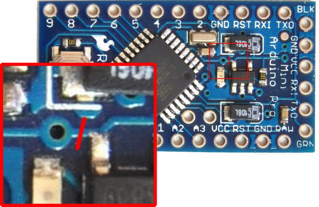
Here is the trace you need to cut to bypass all the voltage regulation crap:
link textIf you have one of the cheap boards, I would cut the PCB trace first and retest before buying new stuff. Let me know what happens.
-
@Neverdie: during my low power tests, I have used these http://s.click.aliexpress.com/e/feUvNFufi and it worked like I said. Arduino pro mini, I think you know it, is basically an atmel with some components. And I think most of arduino clones follow Arduino reference schematics. Just rooting and placements is different. So, in theory, it should work. but maybe bad components like capa, and I am not sure, could be the cause. but, in this case, it means that you can't be sure with all clones too and you need to find the good supplier. very strange and not cool. or maybe could it be counterfeil atmel...I don't think.
Did you tried Sketch J from Gammon. Do you have still the problem??
And of course like Brolly said, I removed voltage reg stuff. -
yep. funny you proposed this link, and I checked on my ali orders and it is the same!
what do you mean by "unspecified means". I am not sure....@scalz said:
yep. funny you proposed this link, and I checked on my ali orders and it is the same!
what do you mean by "unspecified means". I am not sure....By "unspecified means", I just mean that you never said how you managed to do it. Rather, you said you'd rather let Charles say how he did it, whenever it is that he feels like he's ready to say.
So, apparently, I was confused. For some reason I thought you had managed to achieve <1uA sleep current in an entirely custom way and that the Pro Mini's from Great Wall Electronics were unrelated to that. That's why when I stumbled across the 3-step article I posted earlier in this thread, I thought I'd just press ahead with that because it made the entire process (seemingly) so simple. Well, it is simple, except all the different "configurations" muddied the water and created doubt about what sleep current I might really get, maybe even depending on which "configuration" I got.
At this point I'd be happy with 3.5uA. Based on the above, it sounds like Brolly759 found a way to reduce sleep currents down even further to 2.5-2.7uA, though I haven't yet wrapped my head around how Brolly759 did it, aside from reverting to IDE 1.0.6. I need to back up and re-read what he wrote now.
-
@Neverdie: ok. this is what I was thinking..ahah no problem. I think you have misunderstood me.
First, I think Brolly knows how to get low power as he said he has studied Gammon sketch. have you?
Then, at the beginning I give you links to achieve low power but you told me that you wanted an easy to do way (the link with coin cell) and told !scalz. So I thought you didn't want to know more.
So, if you want to try these steps and check (this was my first steps):
- arduino pro mini, remove led and voltage reg
- upload sketch J from Gammon, so you will be sure the best you can achieve
- check at your uCurrent you will be < uA
- Mysensors part : make a function from this sketch J and use it for sleeping instead of gw.sleep which use lowpowerlab (very strange I had difference with it and didn't investigated more). but you will need to find something for your radio next...like mosfet but it is other things.
But If you try it, you will see with your eyes now...
Yes I have already some codes. but I told you I don't share as it is experimental, not clean, and a good lib will be released soon. So i don't want to spend more time for nothing.
-
OK I am going to join the party as this is exactly what I have been testing this past week. I have a uCurrent Gold and running on an 8Mhz 3.3v Nano Pro from this site:
https://www.sparkfun.com/products/11114
I have un-soldered the smt jumper to bypass all voltage regulating and running off of 2 AA Batteries.
I am using the BinarySwitchSleepSensor sketch from the MySensors library. This uses pin 2/3 as an interrupt and sleeps until a pin hits GND. It wakes up, sends the new state, and goes back to sleep. The sketch also makes pin 2/3 high and uses the internal pull-up resistor.
Originally I was getting 23-24uA in sleep mode when GND was not connected to pin 2/3. 117uA when GND was connected to pin 2/3. We will refer to this as open and closed pin state.
Here is my methods:
I downgraded my version of Arduino IDE to 1.0.6 from the latest build 1.6.5 and here are my new numbers:2.5-2.7uA sleep mode - Open pin state
98-100uA sleep mode - Closed pin stateThen I deleted from the sketch the digitalWrite on pin 2/3 and used an external resistor thanks to the advice from AWI. I plugged in an 10M Resistor to pin 2 to VCC and GND was the switch. Here are my new numbers:
2.5-2.7uA sleep mode - Open pin state
3.1-3.2uA sleep mode - Closed pin stateSo far today I have not gotten any false positives in my setup which is freaking amazing.
Now I used a quick sketch "DallasTemperatureSensor" from the MySensors library to test what my current would be in sleep mode with a watchdog timer. I did NOT connect a temp sensor but my sleep current is: 7.6uA - 7.8uA.
I hope this helps and if you need any testing let me know.
I have a post on the Arduino forums here:
http://forum.arduino.cc/index.php?topic=341958.msg2360300#msg2360300You can see me talking to the guy who actually wrote up the gammon website and you can ask him things directly if you ever wanted too. Very helpful guy!
@brolly759 said:
OK I am going to join the party as this is exactly what I have been testing this past week. I have a uCurrent Gold and running on an 8Mhz 3.3v Nano Pro from this site:
https://www.sparkfun.com/products/11114
I have un-soldered the smt jumper to bypass all voltage regulating and running off of 2 AA Batteries.
I am using the BinarySwitchSleepSensor sketch from the MySensors library. This uses pin 2/3 as an interrupt and sleeps until a pin hits GND. It wakes up, sends the new state, and goes back to sleep. The sketch also makes pin 2/3 high and uses the internal pull-up resistor.
Originally I was getting 23-24uA in sleep mode when GND was not connected to pin 2/3. 117uA when GND was connected to pin 2/3. We will refer to this as open and closed pin state.
Here is my methods:
I downgraded my version of Arduino IDE to 1.0.6 from the latest build 1.6.5 and here are my new numbers:2.5-2.7uA sleep mode - Open pin state
98-100uA sleep mode - Closed pin stateThen I deleted from the sketch the digitalWrite on pin 2/3 and used an external resistor thanks to the advice from AWI. I plugged in an 10M Resistor to pin 2 to VCC and GND was the switch. Here are my new numbers:
2.5-2.7uA sleep mode - Open pin state
3.1-3.2uA sleep mode - Closed pin stateSo far today I have not gotten any false positives in my setup which is freaking amazing.
Now I used a quick sketch "DallasTemperatureSensor" from the MySensors library to test what my current would be in sleep mode with a watchdog timer. I did NOT connect a temp sensor but my sleep current is: 7.6uA - 7.8uA.
I hope this helps and if you need any testing let me know.
I have a post on the Arduino forums here:
http://forum.arduino.cc/index.php?topic=341958.msg2360300#msg2360300You can see me talking to the guy who actually wrote up the gammon website and you can ask him things directly if you ever wanted too. Very helpful guy!
If you removed your switch from the equation and just had the arduino pro mini sleep and never wake up (yeah, I know, it's a NOP), what sleep current would you get? That's the sleep current I've lately been trying to measure, because it's the simplest, base case, and you can add current drains to that, as needed.
-
This is testing using the Binary Switch Sleep sketch.
The switch is not active when its in its "open state" so there is no drain. I removed the resistor though and all the jumpes, I am still getting around 2.7-2.8uA is sleep mode without switch.
In sleep mode with the NRF ONLY VCC unplugged I am getting 1.3uA - 1.5uA.
In sleep mode with ALL cables unplugged from NRF I am getting a strange reading and not really sure which one is accurate but here are my numbers:
With uCurrent in uA mode I am getting .4uA -.5uA
With uCurrent in nA mode I am getting 110-120nAI checked on Gammon site using the reference code, the nA of 110-120nA is accurate and the uA mode is wrong when I go down that low. So in short, I am getting 110-120nA when nRF is unplugged completely.
-
@Neverdie: ok. this is what I was thinking..ahah no problem. I think you have misunderstood me.
First, I think Brolly knows how to get low power as he said he has studied Gammon sketch. have you?
Then, at the beginning I give you links to achieve low power but you told me that you wanted an easy to do way (the link with coin cell) and told !scalz. So I thought you didn't want to know more.
So, if you want to try these steps and check (this was my first steps):
- arduino pro mini, remove led and voltage reg
- upload sketch J from Gammon, so you will be sure the best you can achieve
- check at your uCurrent you will be < uA
- Mysensors part : make a function from this sketch J and use it for sleeping instead of gw.sleep which use lowpowerlab (very strange I had difference with it and didn't investigated more). but you will need to find something for your radio next...like mosfet but it is other things.
But If you try it, you will see with your eyes now...
Yes I have already some codes. but I told you I don't share as it is experimental, not clean, and a good lib will be released soon. So i don't want to spend more time for nothing.
@scalz said:
I think you have misunderstood me.
Sounds that way. Probably my fault, due to lack of sleep.
- check at your uCurrent you will be < uA
Excellent!
Next step for me: placing an order with Great Wall Electronics for 10x pro mini's, as that is now critical path. By the time it arrives (hopefully even sooner), l should have this figured out.
-
BTW, while on Great Wall, I noticed these RTC functional knock-offs of the Chronodot are just $0.57/each.
It might make sense to use one of them to wake up an arduino just once, when it needs to be woken, instead of every 8 seconds, as when using the Watchdog Timer. The current consumed by a genuine ChronoDot is: 200uA (active), 840nA (timekeeping) I don't have amp figures for the Great Wall knock-offs. I have a couple of the genuine chronodots, and they keep pretty accurate time.
-
We really need a separate section just on power consumption, what each person gets per each configuration and instructions lol.
I have never played with the Chronodot or any time stamp stuff. Is is easy to program?
It does make sense to remove the watchdog timer: 7uA current with this but, who wants to do the math? What is the rise/fall time of the Chronodot? Depending on the duration of the rise time and frequency of waking up the arduino, we may not be saving much power. (Algebra was never my strong suite. Never went to college lol)
On a side note, I am working with Gammon on figuring out why the nRF takes so much power: 2.4uA in sleep mode. Though I don't have any hardware at home so we must wait until tomorrow for that. In theory Arduino = 100+- nA + 800-900nA(NRF) = 1uA in sleep mode with an interrupt. That is what we all need to be aiming for, or at least I am.
-
I think I spoke too soon. For battery applications, probably by now there are better options.
-
Look at this one:
http://ambiqmicro.com/am18xx-ultra-low-power-rtc14nA !!!! haha
-
Wow! Good find. LOL. I was just about to post the following, as a "for instance," but you already found something that's 2-7x better.
"For instance, Digikey now sells a$14.40 eval board with a newer RTC clock on it that consumes just 100na: http://www.digikey.com/product-detail/en/OM13512/568-11550-ND/4947022
That one uses SPI bus, but there's an I2C variant."I'd really prefer that it be built into the MCU anyway. These things are just the bridge to that. If the WDT could have timed beyond 8 seconds to hours or days, we might not even be talking about it. Apparently it was meant for rebooting the MCU if the MCU got wedged, not for sleeping the MCU for hours or days. It illustrates how long overdue the arduino is for a major updating.
-
You may want to check how the mySensors library actually works. I barely know hardware and coding, I scrape by... lol but in all the sensor examples you have this code:
unsigned long SLEEP_TIME = 30000; // Sleep time between reads (in milliseconds)gw.sleep(SLEEP_TIME);That is a 30 second duration for sleep. I haven't tried to increase that time yet but maybe they are looping through the 8 second limit? Dunno. Worth to check though how they do it.
My issue is that this sleep method uses 7.6-7.8uA. It would be nice to have it at like < 3uA.
-
I am digging around and looking at the code, I think it just cycles through 8 second batches.
We have an unsigned long, so thats 4,294,967,295 ms = 4294967.295 seconds = 71582.78825 minutes = 1193.046470833333 hours = 49.71026961805556 days.
So IF there is not a cap on the max duration of sleep in the Mysensors library, you can theoretically go to sleep for the max duration of the unsigned long which is about 49 ish days...